REVIT_Creation of Basic Drawing_Week 2
1). Building Information Modelling (BIM) is the digital representation of physical & functional properties of a facility.
Building Information Modelling helps design and construction teams to communicate about design and axis information across different levels that has been used before. This informationremains with the project, right from the start, throughout its lifetime. It also helps to analyse any potential impacts.
1) Conflict detection and Risk Mitigation.
2) Coordination and Collaboration.
3) High Level of Customisation and Flexibility. 4)Optimization of Schedule and Cost.
5)Easy Maintenance of Building Life Cycle.
6)Faster Drafting without loss of Cost and Quality. 7)Competitiveness
8) Easy access to Information.
9) Increase in Efficiency and Productivity.
2) .
AIM: To choose an element from the families present in different categories and insert it into the file.
TOOLS/COMMANDS USED:
Insert
Load Family
Instances
Elements
Categories
PROCEDURE:
Step-1: open the created Revit file.
Step-2: from the insert tab select the load family property.
Step-3: A dialog box of categories under families appears.
Step-4: Select an element and select the required instance.
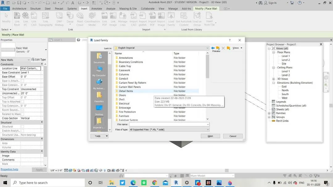
RESULT:
The selected element from the family will be placed in the file.
3).
AIM: Setting up a new project and set up the maximum backups to 3.
TOOLS/COMMANDS USED:
File
Save
Manage
Options
No. Of backups.
PROCEDURE:
Step-1: Open Revit.
Step-2: Open file and choose new and select project.
Step-3: Choose imperial architectural template and click OK. Step-4: Open the manage tab and select project information. Step-5: Now a dialog box of project information will pop out. Step-6: Fill the details in the project information box.
Step-7: Now click on save as and select project.
Step-8: Now a dialog box opens, select options which is present at the bottom right.
Step-9: Now another dialog box of file save options and change the maximum number to 3.
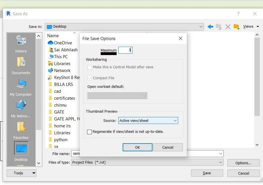
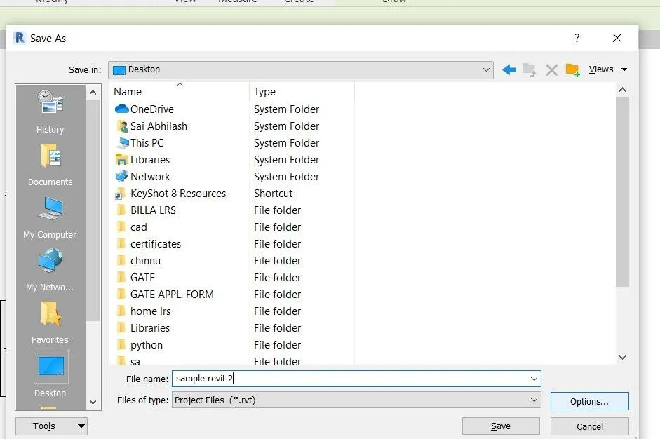
RESULT:
The project with 3 backups is created successfully.
4).
A) Levels and Grids are finite planes that help to define the project context.
AIM: To create different levels and name them as required accordingly to the question First Floor @ 10’
Second Floor @ 20’ Roof @ 30’
TOOLS/COMMANDS USED:
Architectural wall
Elevations
Levels
PROCEDURE:
Step-1: Open Revit and select construction template.
Step-2: from the project browser select any of the elevations (say ‘EAST’)
Step-3: Now different levels appears on the screen.
Step-4: select the different levels from the bottom and adjust the heights as required.
Step-5: name the levels as given in the queestion.
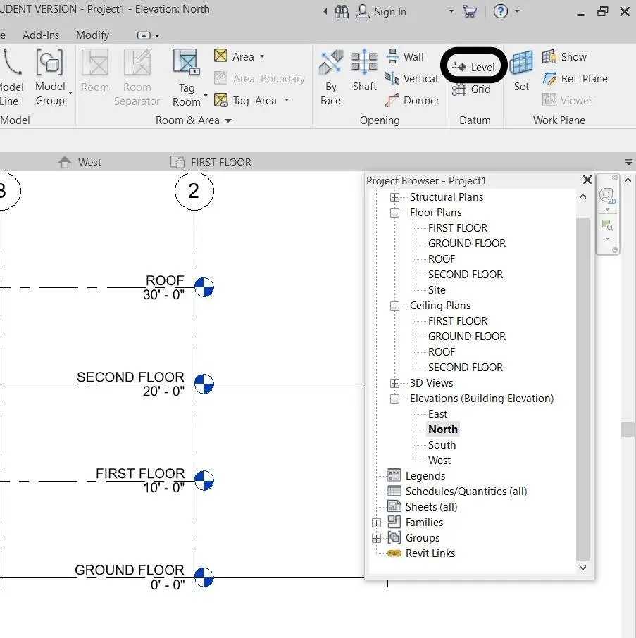
RESULT:
The levels at required measurements are obtained successfully and named accordingly.
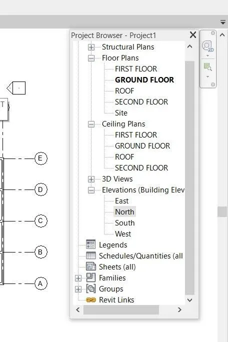
B) For transverse grids the naming will be given from bottom to top in an ascending order.
For longitudinal grids the naming will be given from right to left in an ascending order. Grids can be named either with A, B, C…. Or with 1, 2, 3….
AIM: To form different types of grids.
TOOLS/COMMANDS USED:
Construction template
Grid
Architectural tool bar
PROCEDURE:
Step-1: Open the Revit software and select construction template.
Step-2: Select the architectural tool bar.
Step-3: Now select the grid option at the right corner of the architectural tool panel.
Step-4: Draw five transverse grid lines and name them as A, B, C, D & E of offset 10’.
Step-5: Now draw ten longitudinal grid lines and name them 1-10 and of offset 20’.
RESULT:
The grids of required grid lines with given offsets are drawn successfully.
5).
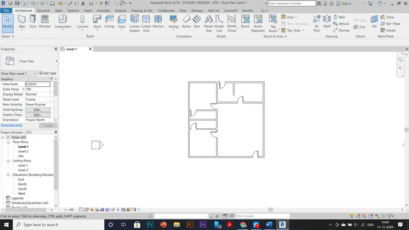
AIM: To create a layout specifying a residential unit.
TOOLS USED:
Architectural template
Architectural walls
PROCEDURE:
Step-1: Open a Revit file choosing the architectural template.
Step-2: Now go to the file tab and save the project name as residential building.
Step-3: Select the wall icon from the architectural tab.
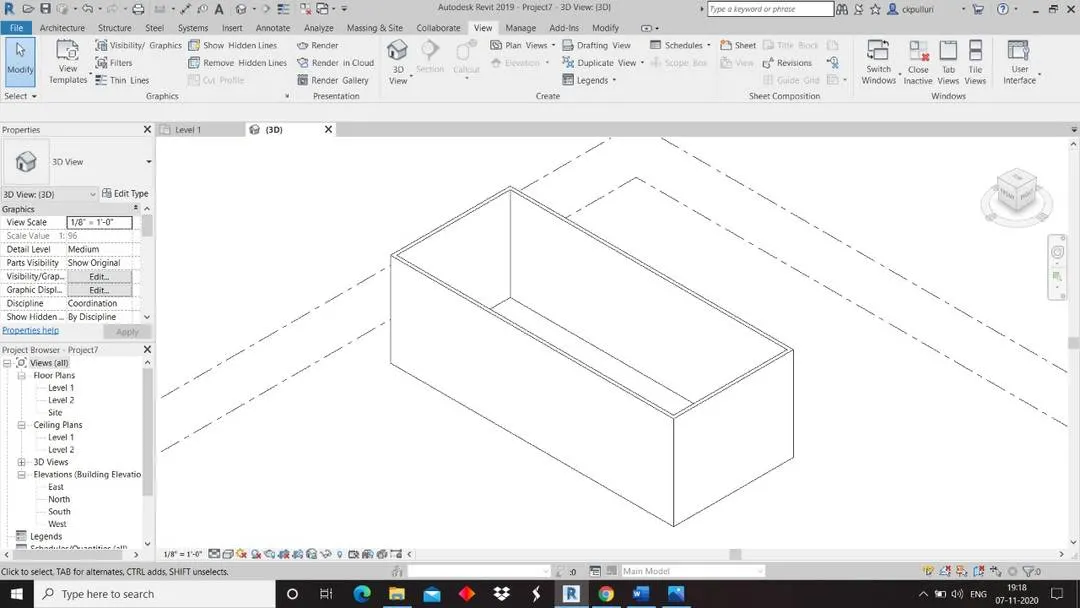
Step-4: Now place the walls of dimensions 27’-0” X 52’-6”.
RESULT:
A layout of a residential layout is created successfully.
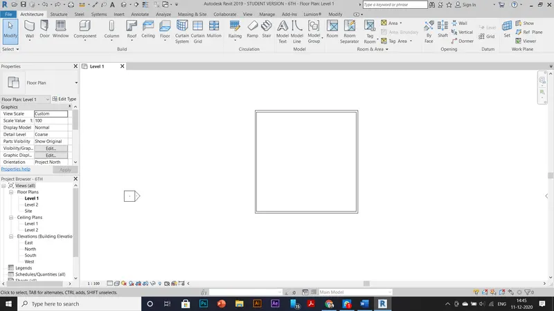
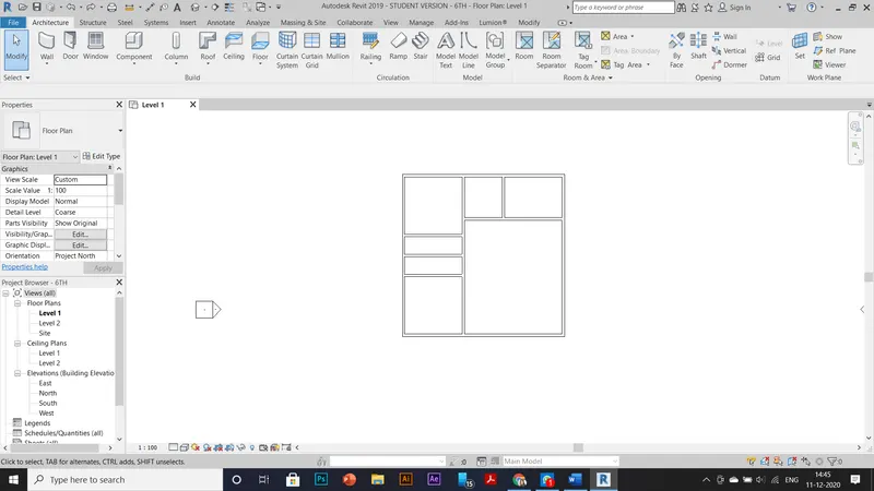
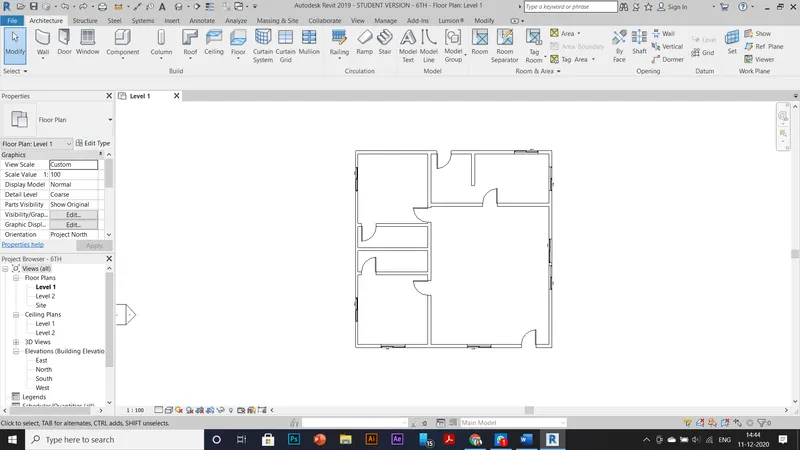
6) AIM: To draft the level of details in the residential layout.
TOOLS/COMMANDS USED:
Annotate tool
Aligned dimension
PROCEDURE:
Step-1: Open the same file i.e., previously saved as residential building.
Step-2: use the alignment property to measure the dimensions of the layout
RESULT:
The dimensions of the rooms in the residential building layout are measured
successfully.
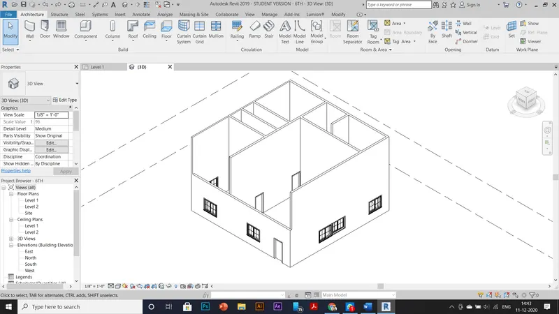
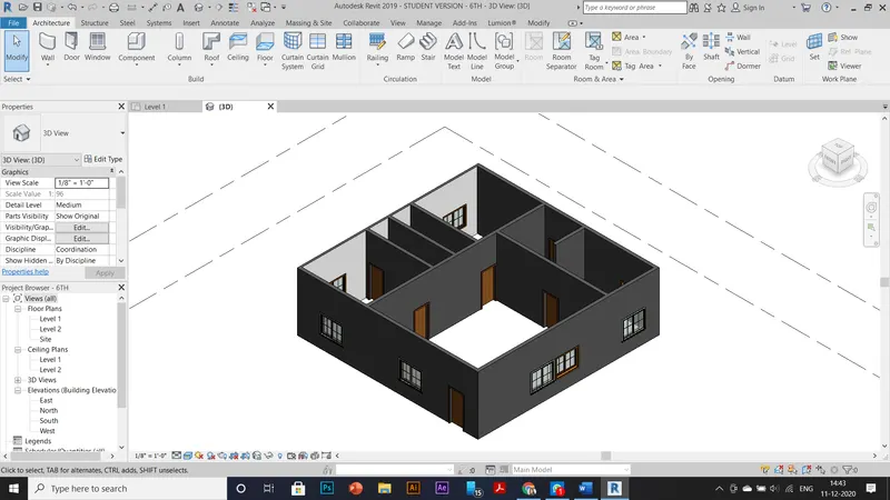
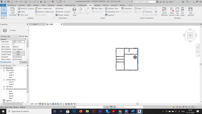
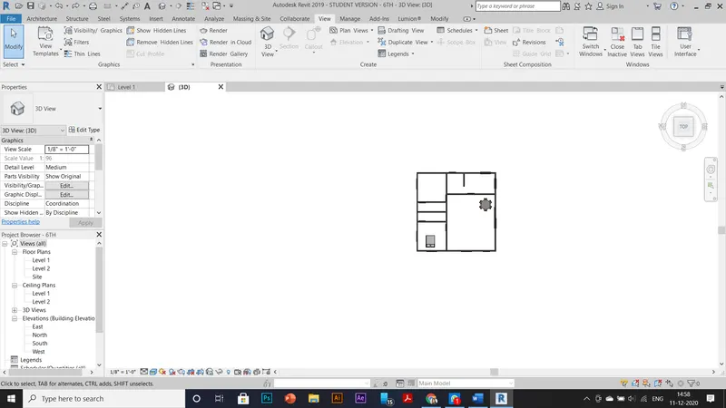
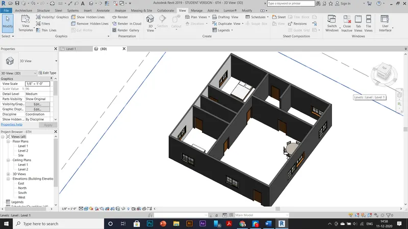
7) AIM: To insert the residential building models in the residential building layout.
TOOLS/COMMANDS USED:
Architectural tool bar
Insert tool bar
Load Families
Doors
Windows
PROCEDURE:
Step-1: Go to the previous residential building layout.
Step-2: Select the doors and windows.
Step-3: Go to insert tool bar and select load families and get the models required for the residential building.
Step-4: as per the usage place the models according to their placement rooms.
Step-5: Change the orientation of the required models by modify tool bar.
Step-6: Save the project.
RESULT:
The residential building models are inserted successfully in the layout.