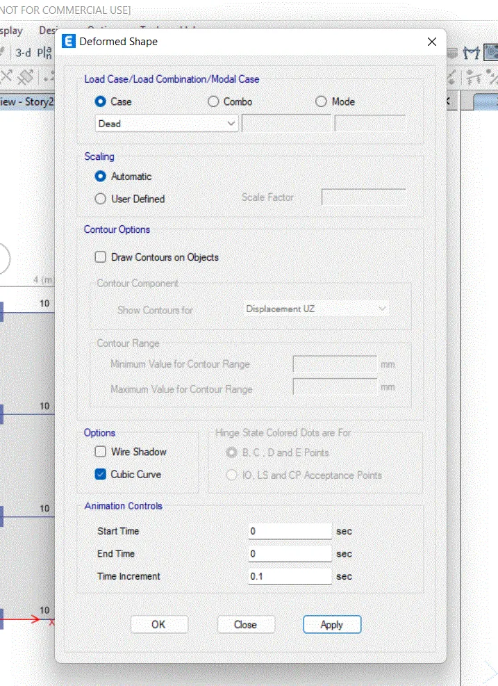
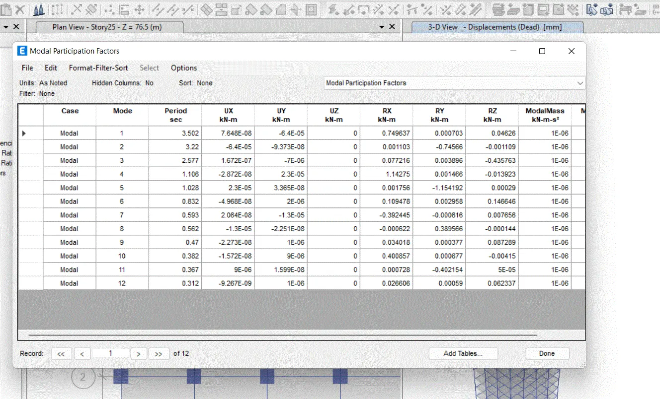
Modelling of 25 storey building with the specified properties using ETABS
AIM:
- To modelling a 25 storey building on etabs 2020 with structural properties including ground floor or plinth level at a height off 1.5 meters from the base and a story height of 3 meter
PROCEDURE:
- Open ETABS 2020 application
- Click the file menu and choose to create a new model option ffrom there
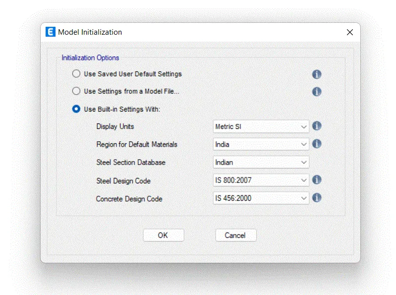
- After choosing a new model a dialogue box will appear which is known as model initialization
- Choose the built in setting option and select the display units and codes
STEP 2
- After the model initialization needs to select grod and story inputs from the new model quick template dialogue box
- In this dialogue box choose custom grids spacing and custom story data which is used to provide the inputs whatever we want
- Click ok
STEP 3
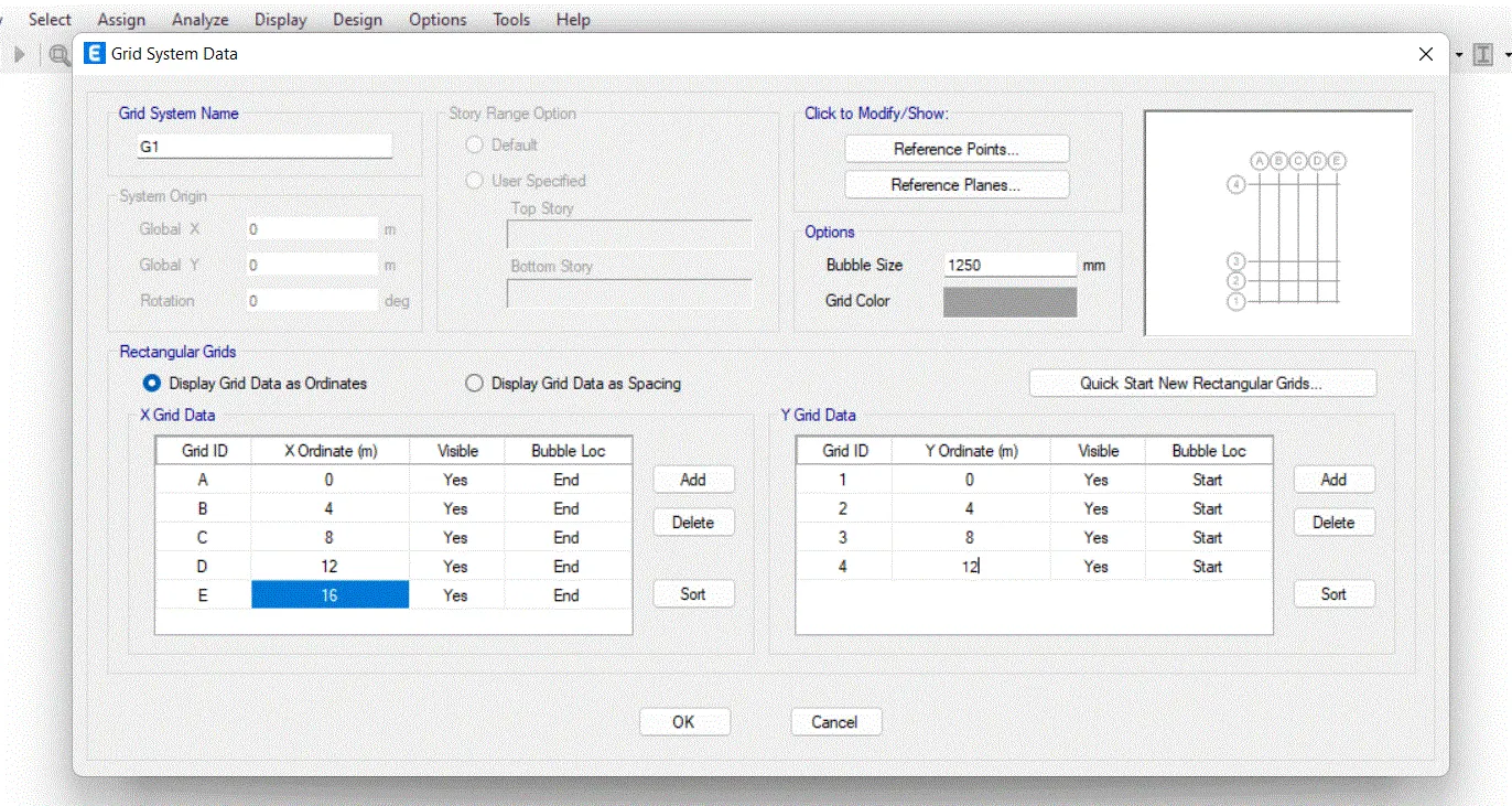
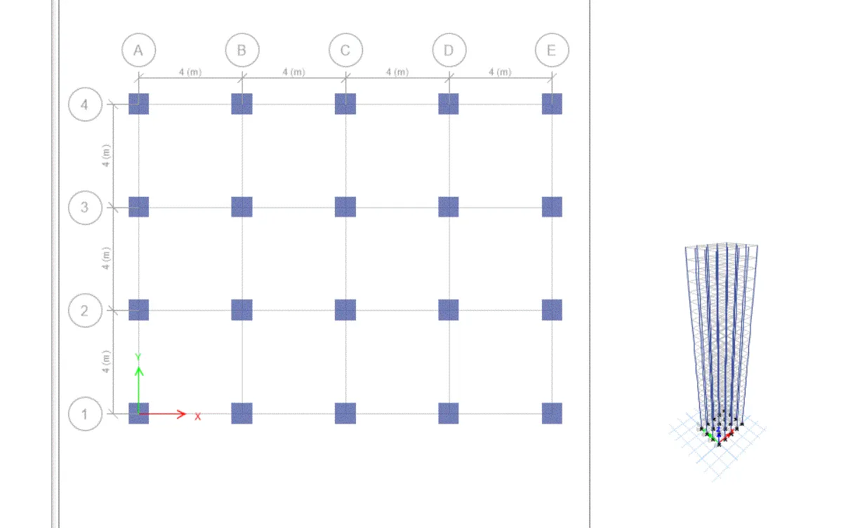
- In the grid system data dialogue box,set x grid data as 5 number at a distance of 4m
- Set Y grid data as 4 number at a distance of 4m
- Click ok
STEP 6)
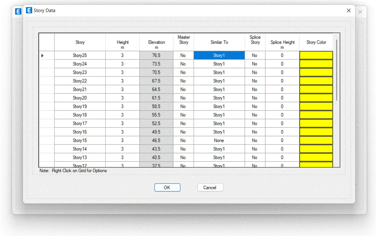
- In a story data dialogue box ,need to input all the relevant details about the story which we want to model
- Click add story and add 21 more story
- Put 3m height for all the story exceot plinth
- MAke first story as master story
- Choose all other stories as similar to first story
STEP 7)
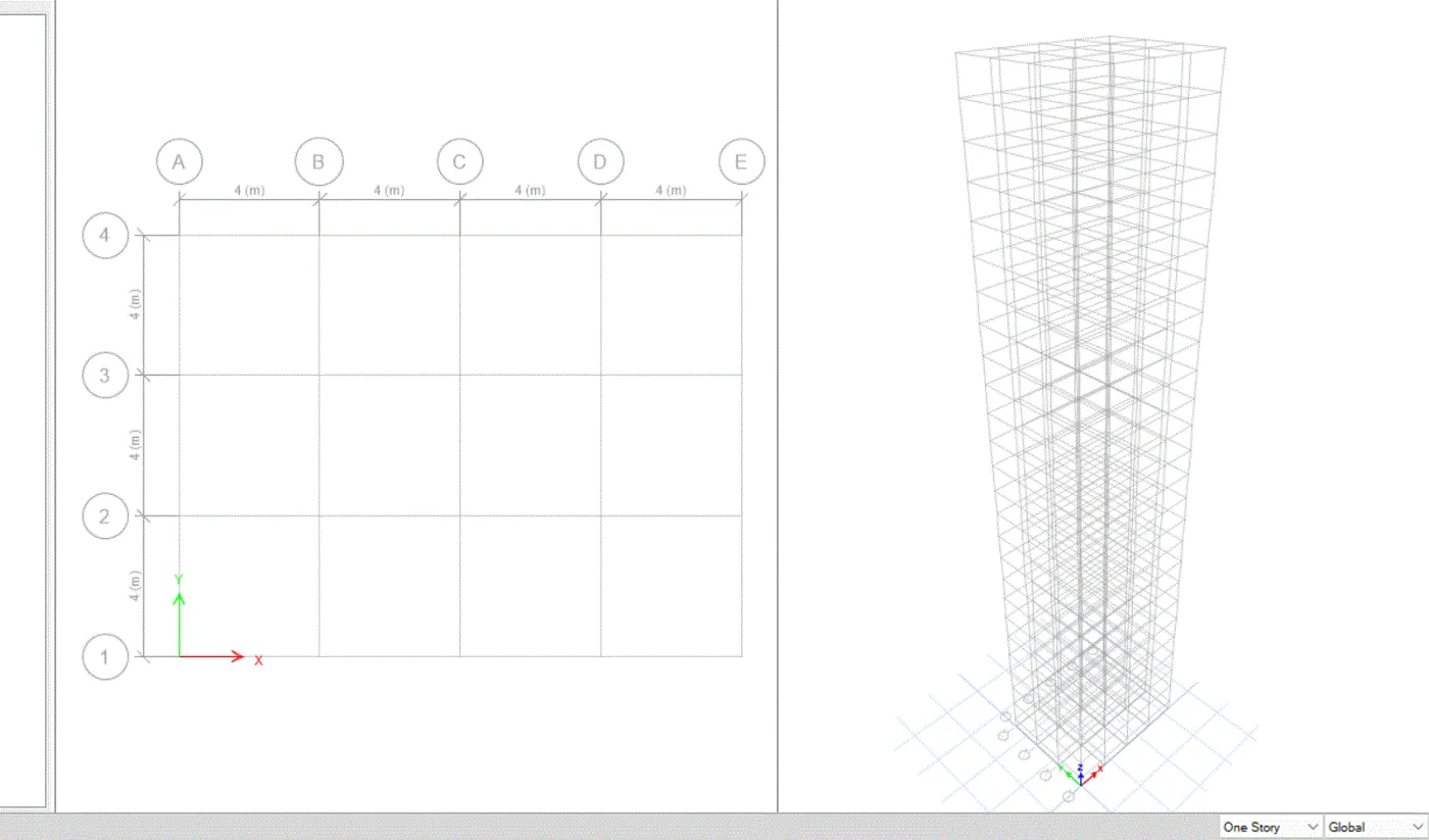
- On the top right corner click the drop down arrow
- Choose new window option
- Now the screen splits into two
- Here,we can see the plan and elevationof each story simultaneously
STEP 8)
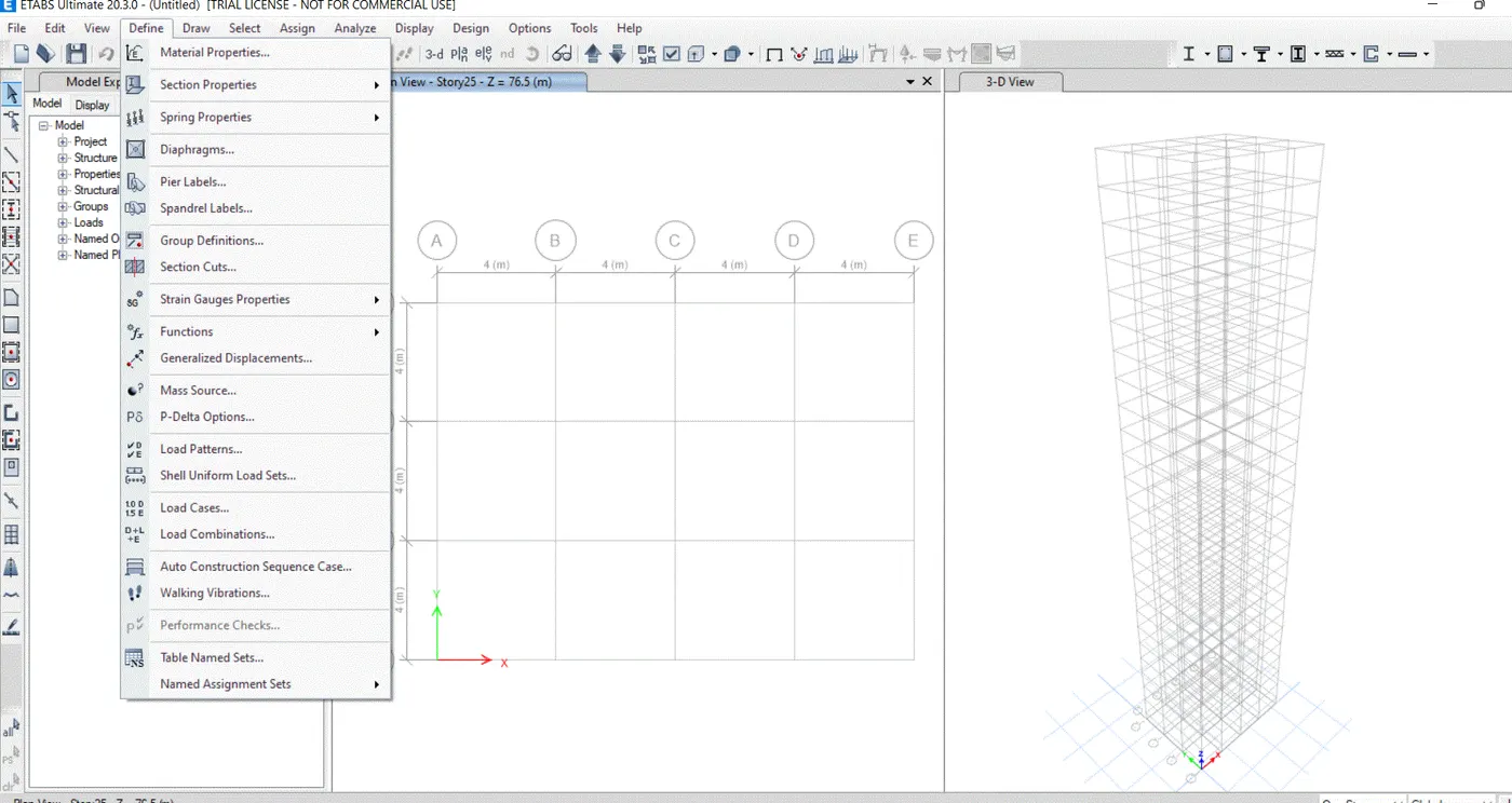
- Click Define tab
- Choose material properties
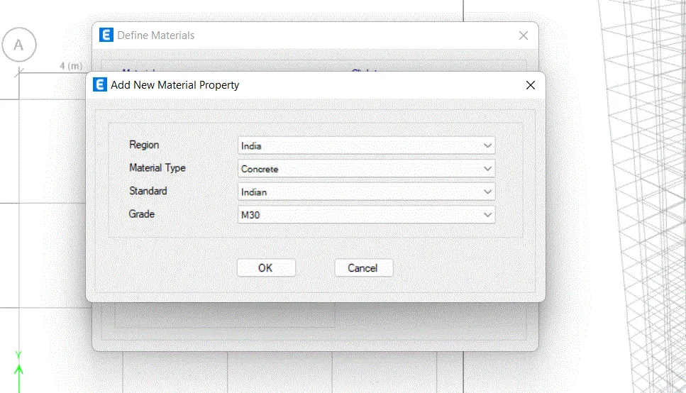
- After selecting material properties from the define tab , adialogue box will appear.In this dialogue box select regions as india
- Similarity choose all other inputs like material type,standard grade accordingly
STEP 8)
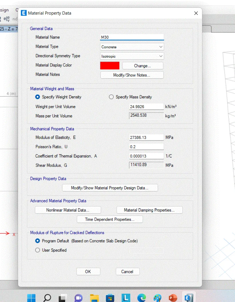
- After Clicking ok fopr add now material property dialogue bix it redirects into another dialogue box called material property data
- In this all the relevant data values are assigned default as per IS code which we have seen previously
STEP9)
- After applying the properties of beams and column we need to apply the property of slab
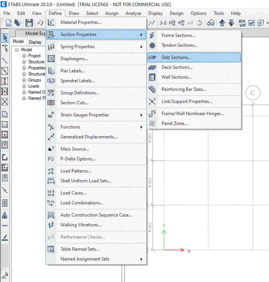
- Click define menu and choose section properties
- Select slab sections
STEP 10)
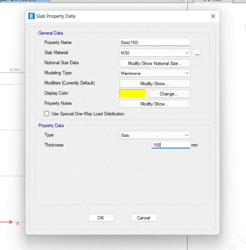
- Click to select add new property
STEP 12)
Drawing of column and beams
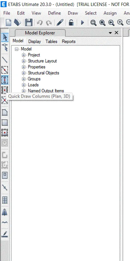
- To drawing the column and beams in ETABS just click the quickdrawcolumn tool in the model tree
- After Clicking the tool, the property tab will appear on that all the relevant detail about the particular objects will show
STEP 13)
- Draw the column in accordance with grid
- Click the select object tool to discard the drawing
- STEP 4)
- Applying Loads
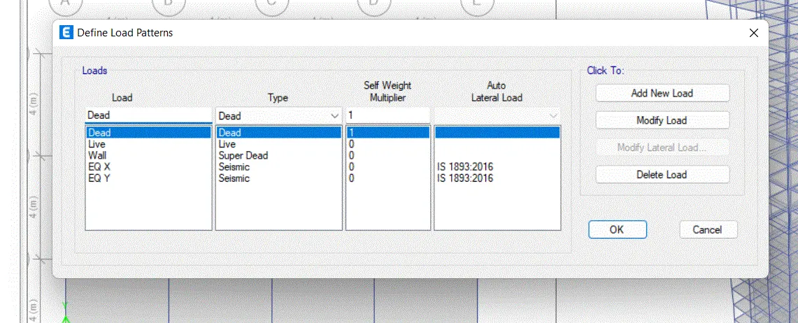
1) Click Define tab
2) Choose Load pattern
3) Add new load as brickwait ,EQX with both positive and negative eccentricity as per is 1893:2016
4)Similarly add EQy with positive and negative eccentricity
5)After providing the names and codes of load
6)Click modify lateral load option
7)Set story rage as a base to top
8)Assume the zone as zone IV
STEP 7)
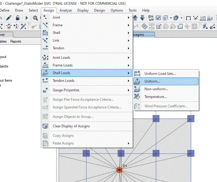
- After providing the load inputs need to assign the shell loads of each story
- Change tab as similar story
- Select the entire grid
- Click the assign tab and choose shell loads
- Select Uniform
STEP 18)
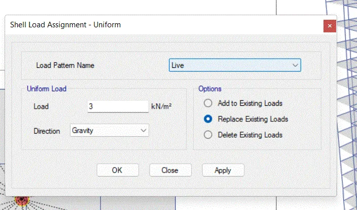
- Choose the load pattern name as already set in previous step
- Input the load as 3 Kn/sq.m as given in the question
- CLick ok
STEP 19:
- Similarly we need to assign the live load for all the beams
- Click ok select tab
- Choose object type select beams
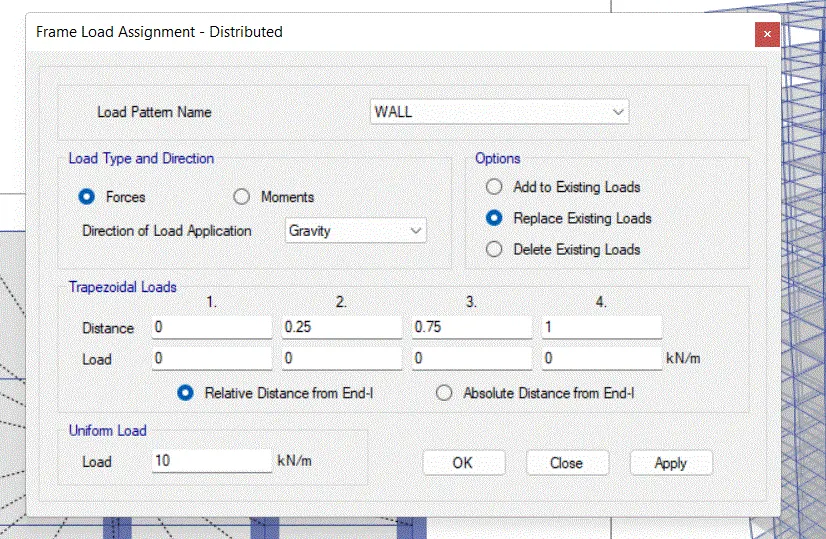
STEP 20)
1) Choose the load pattern name from the drop down list
2)Set load as 10kn/sq.m
3)CLick ok
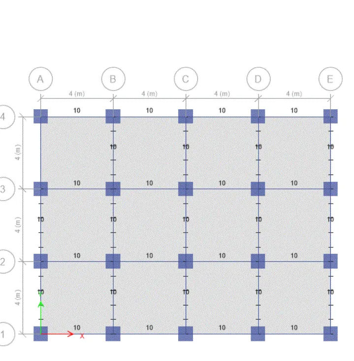
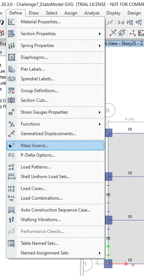
STEP 22:
1) Before running the analysis we have to set one more steo i.e. mass source
2) Go to the define tab
3) Select the mass source option
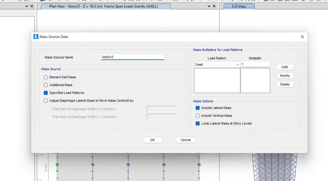
STEP 23)
- Tick mark the specified load pattern
- Add the load pattern which we want to assign the model
- Click ok
STEP 24)
- One of the important steps for modelling is to set load combination
- Click the define tab
- Select the load combination
STEP 25)
- Choose the load combination
- Select the concrete frame design
- CLick ok
STEP 26)
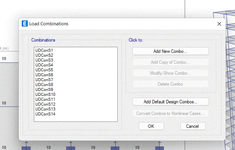
1) Immediately ETABS will give you various load combination as per code which we ware set previously
2) CLick ok
STEP 27)
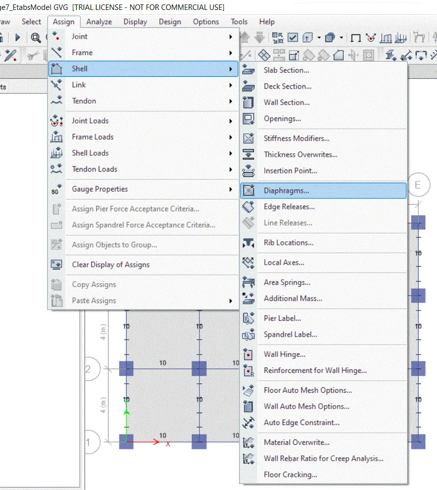
1) Final step of analysis is to set diaphragm
2) Click the assign tab
3) Choose shell and select diaphragm
4) Choose an all story option from the bottom of the screen
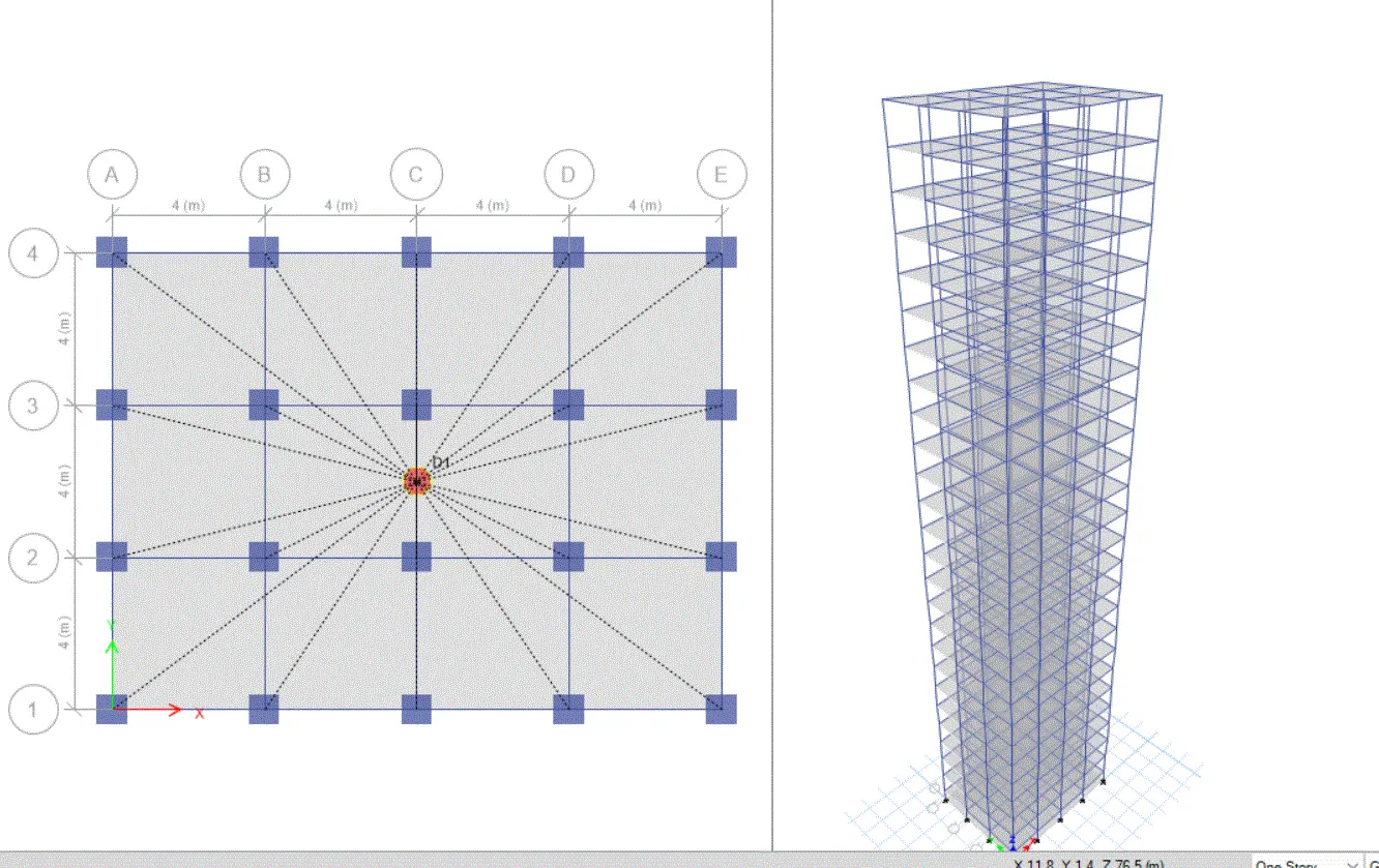
- Click the check tab and check the model
RESULT
- After the analyis option click result tab
- We can see the result by selecting the loads separately