Modelling of 25 storey building with the specified properties using ETABS
Modelling of 25 storey building with the specified properties using ETABS
Jagadeep.M.M
AIM:
To create & Analyse 25 storey building using ETABS.
INTRODUCTION:
- ETABS(Extended Three-Dimensional Analysis of Building System) is a product of computers & Structures Inc.It is a Engineering software that is used in construction for structure analysis & design.It is loaded with an integrated system consisting of modeling tools & templates, code based load prescriptions, analysis method & solution techniques.
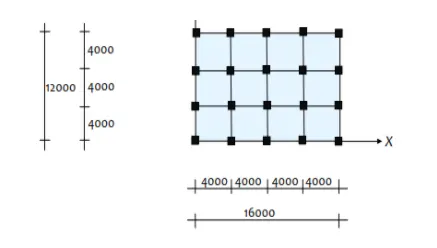
Model a 25 storey building on ETABS with structural properties as specified below. Ground floor or plinth floor level can be taken at a height of 1.5 metres from the base. Each of the successive 25 storeys has a storey height of 3 metres.
Structural Element Sizes
- Beams : 300 × 400 mm
- Columns : 800 × 800 mm
- Slab : 150 mm thick
Material Properties
- Grade of Concrete : M30
- Grade of Steel Reinforcement Bars : Fe 415
Loading
- Dead Load on beams from infill wall : 10 kN/m (Let us assume the same for roof floor in view of parapet)
- Live load on floor : 3 kN/m2 (Let us assume the same for roof floor)
a) Buildings are assumed to be pinned at the base
b) All columns in all storey are of the same size
c) All beams in all storeys are of the same size
d) Building is located on Soil type-II and in Zone-III. Assume other factors if required.
Procedure:
- Open the ETABS software.
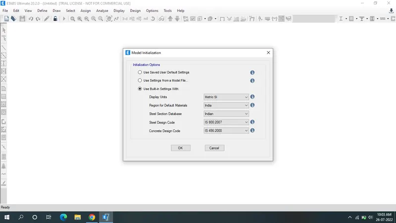
- Click on new model in the file tab.
- Enter detaills in model utilization & click ok.
- Units taken as SI Metric, Steel section database as-Indian, Steel design code as IS-800-2007,Concrete design code as IS 456-2000.
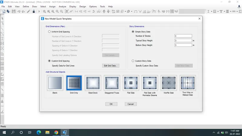
- In New model Quick Templates click on custom grid spacing & enter X,Y grid data as shown below.
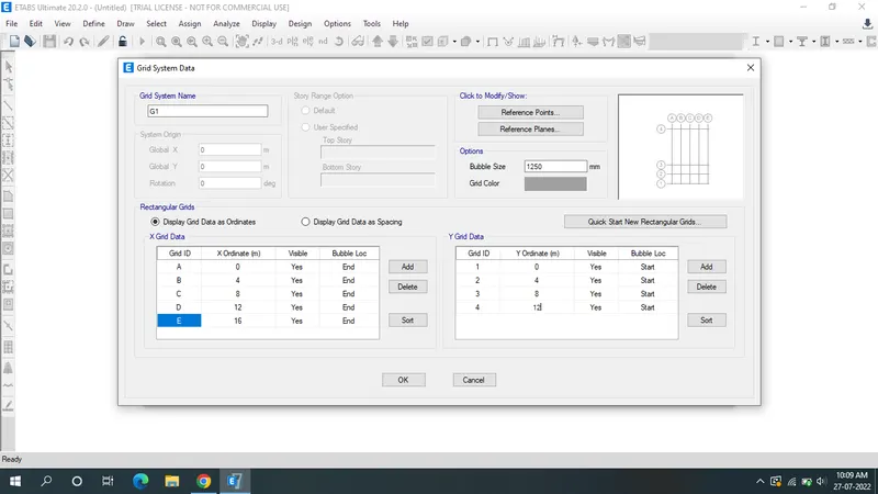
- Press ok.
- Next click the storey & create 25 storeys with ech storey height of 3m & plinth level height as 1.5m.
- change the master "story 1" as "yes" & remaining storeys as "No".
- Change the "similar" to "storey 1" .
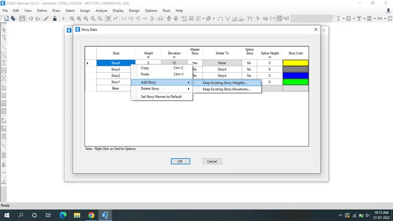
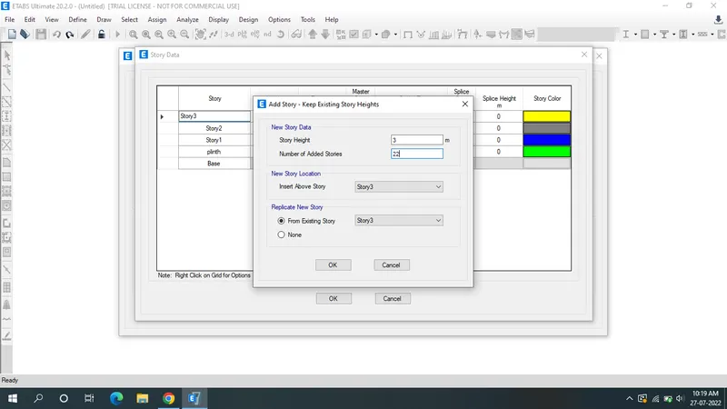
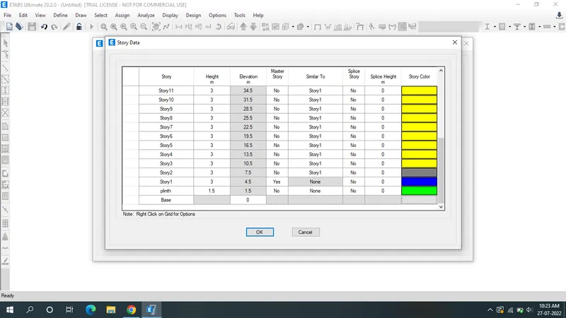
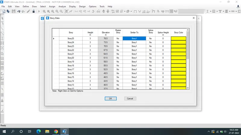
- Click ok.
- The model will be shown below.
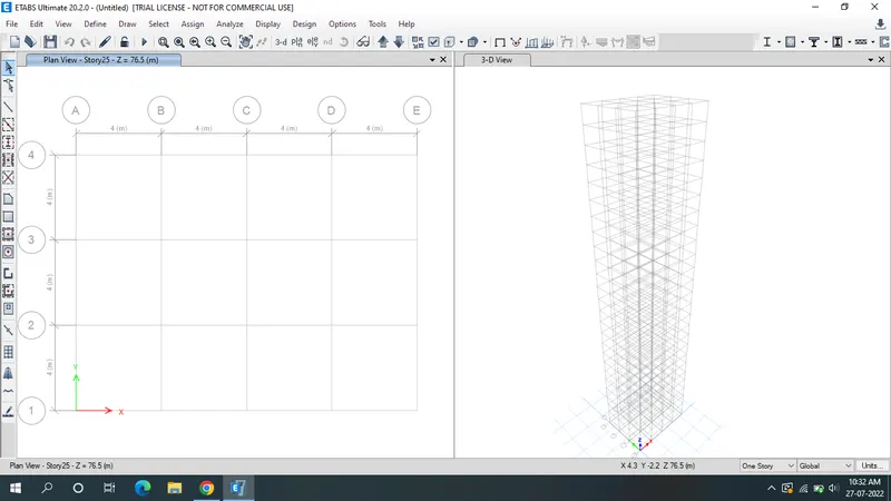
- Now go to "Define" for assigning the properties.
- Click on Material properties.
- Click on "add new materials" (for concrete).
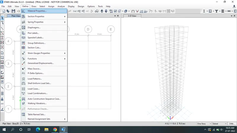
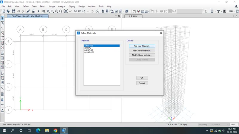
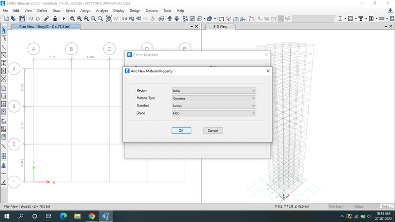
- Similar add another material for steel reinforcement bars.
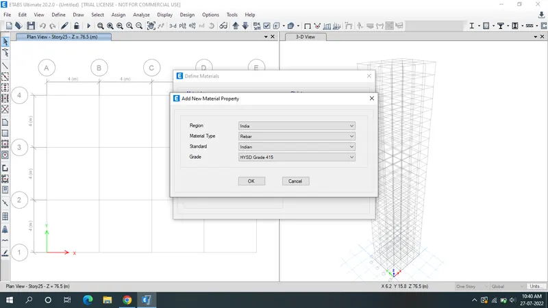
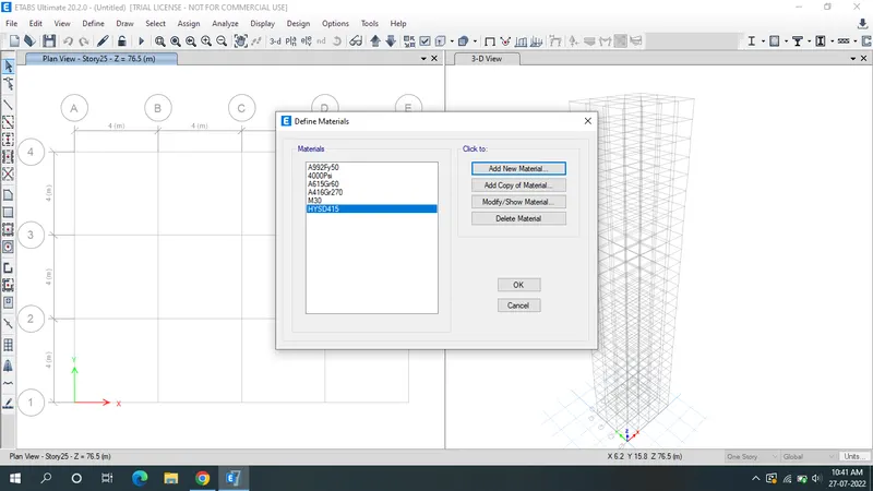
- Define BEAM,SLAB,COLUMN.
- Click on define & select sectin prooerties.
- Select the frame sections.
- Select the frame properties.
- Choose "Add properties" & select concrete.
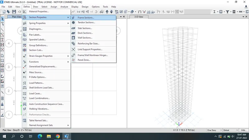
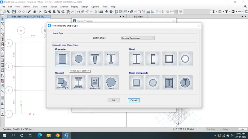
- Frame section property data appears in which enter details to the beam.
- Beam size taken as 300mmX400mm.
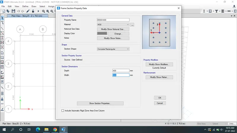
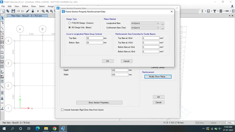
- Select the modify/show rebar & modify reinforcement details as HYSD415.
- To define "column" select the add new property.
- Select the rectangle & enter details of column size as 800mmX800mm.
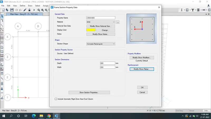
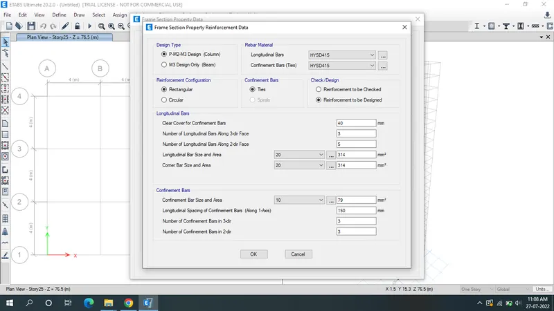
- Select modify/show rebar & modify reinforcement details as shown below.
- Now design slab properties.
- Click on define,go to section properties & select slab properties.
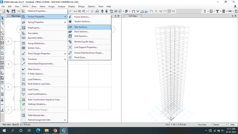
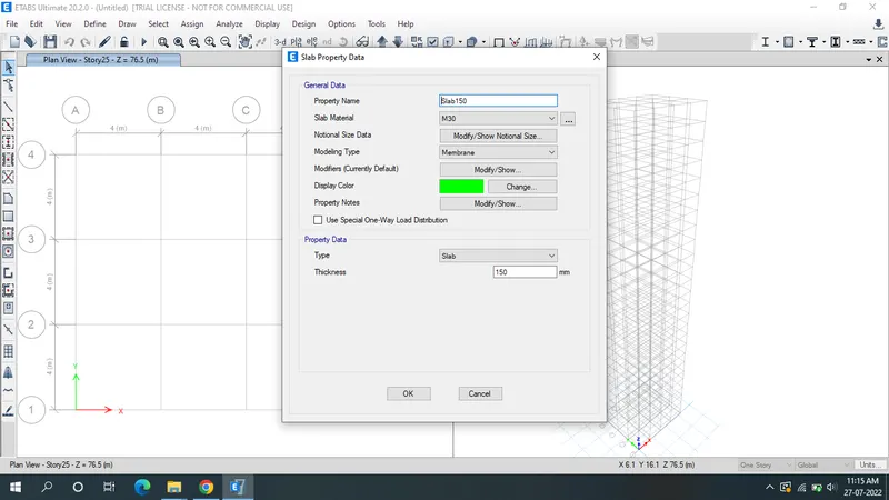
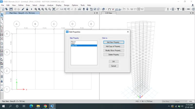
- Click on the add new property & modify it.
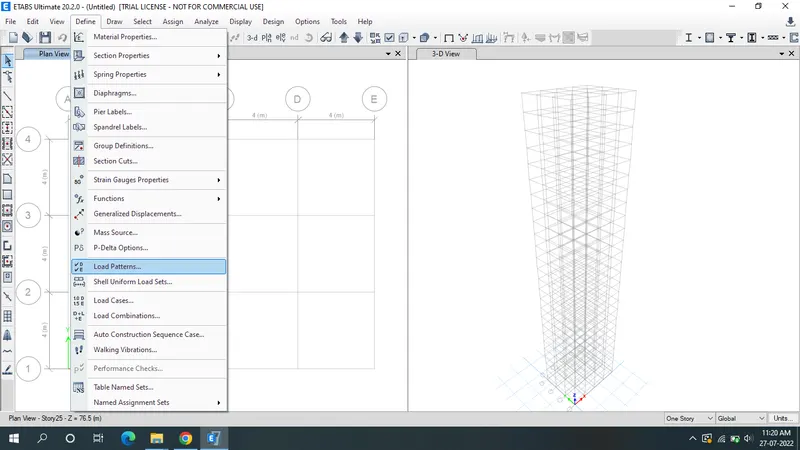
- Define the loads, click on "Define" then select "Load patterns".
- Enter brick wall load as a super dead load & add it as new load.
- Similarly add sesimic loads.
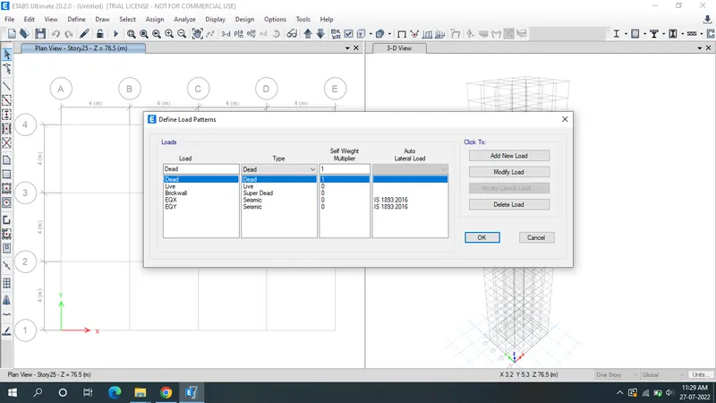
- Modify the seismic loads as shown below in EQX.
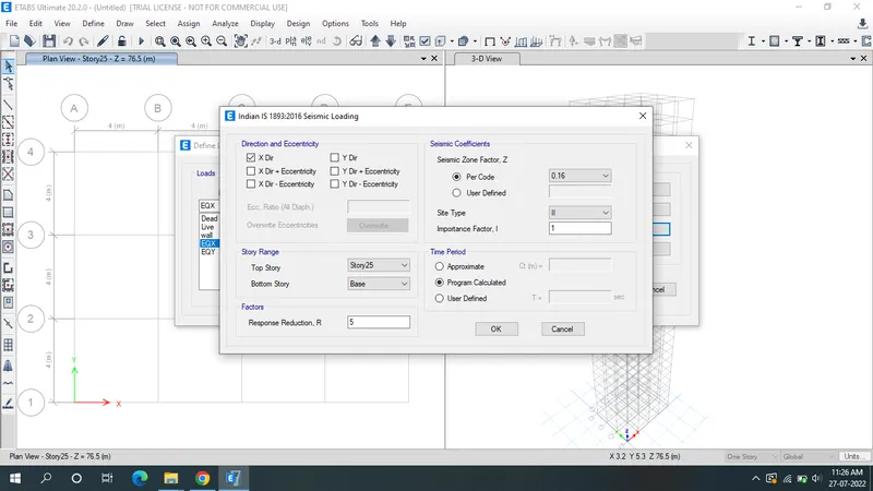
- Modify the seismic loads as shown below in EQY.
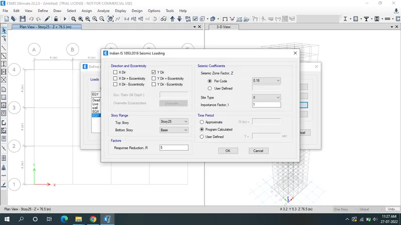
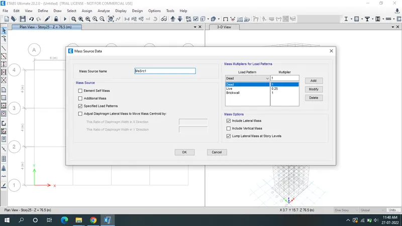
- Assign the mass source.
- Go to "Define" select mass source, click on modify.
- Select only "Specified load patterns".
- Add dead load,brick wall load,live load click ok.
- Live load of the multiplier of 25%.press ok
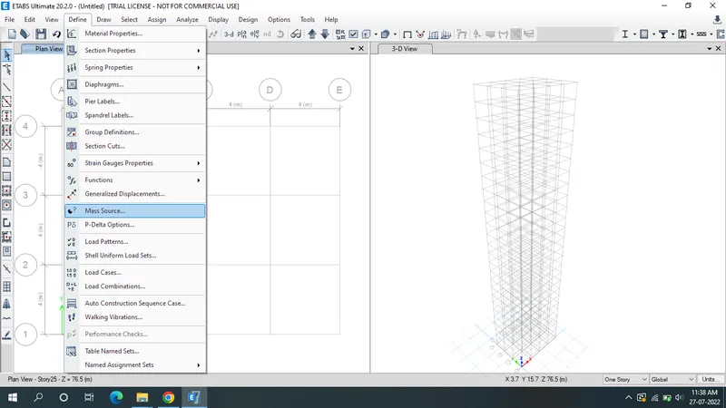
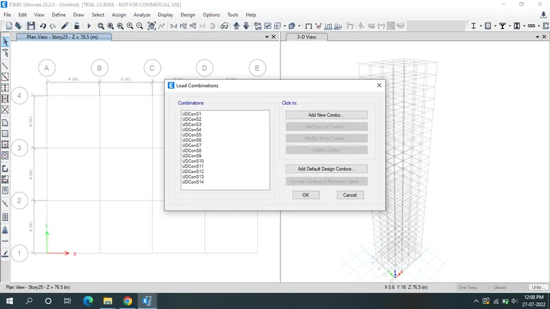
- Click on the "load combination".
- go to "Define", select load combination.
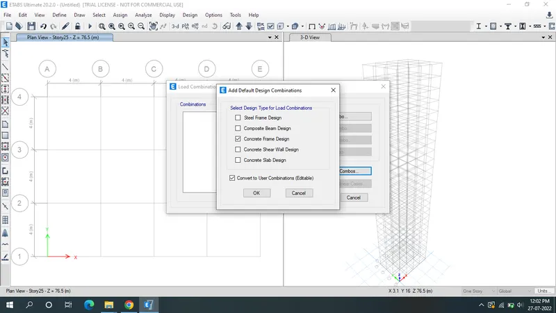
- Select add default design combos.
- Select concrete fram design.
- Select convert to user combination & click ok.
- Click on draw column,select 800X800 column & draw column for all storeys.
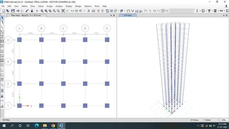
- Click on draw column,select 300X400 beam & draw beam for all storeys.
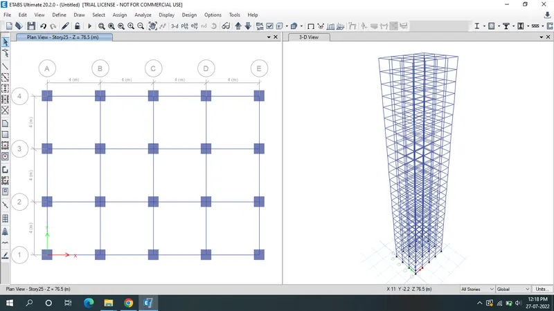
- Click on the Quick draw floor & select the slab 150 & assign.
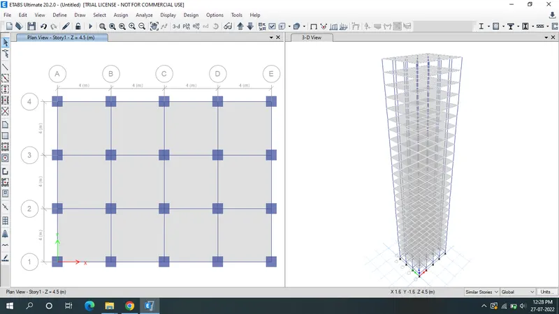
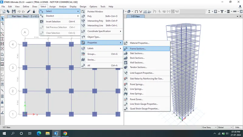
- Go to "select" option & click the "properties".
- Then select the "fram sections".
- select the beam 300X400.
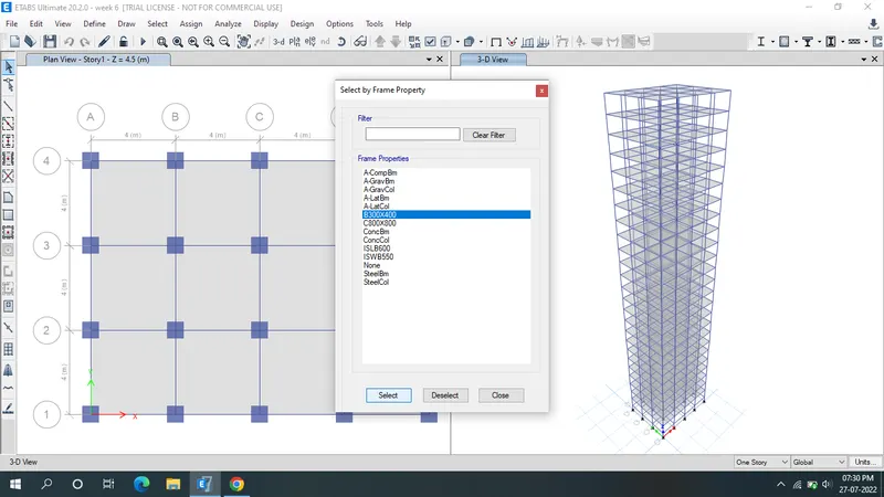
- Click the "assign" & select the fram loads.
- Then select the Distributed.
- Load pattern name as Brick wall.
- Uniform load as 10KN/m, apply ,ok.
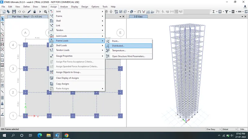
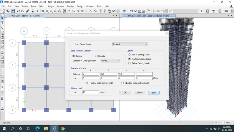
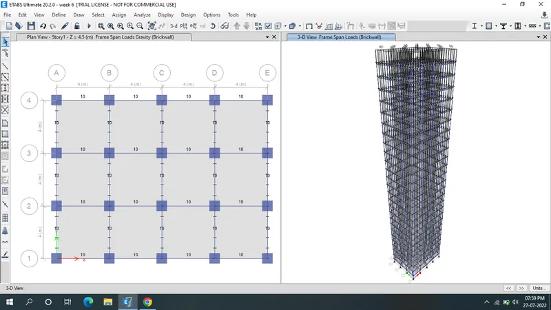
- Click the "Assign" & select the shell loads.
- Click the "uniform", Add the load pattern name as "Live".
- Uniform load as 3KN/m2, apply, ok.
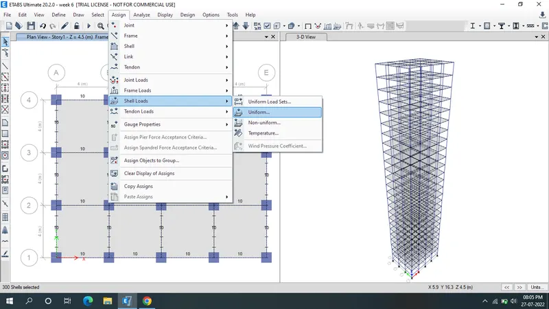
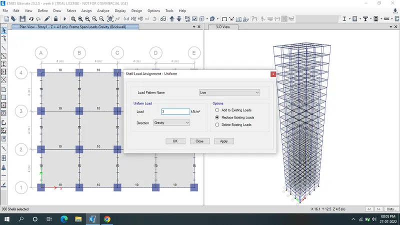
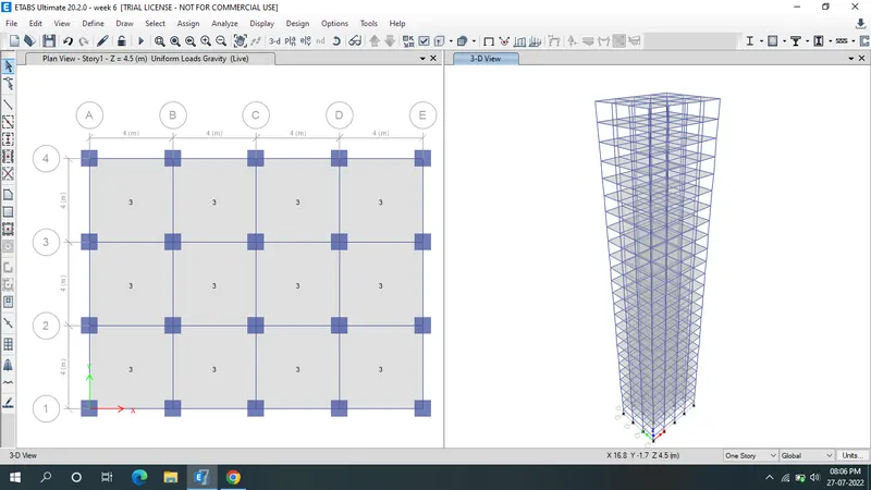
- Again select the slab.
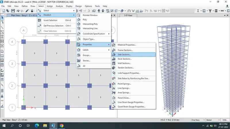
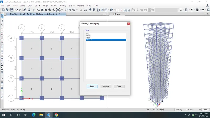
- Click the "Assign" select the shell.
- Then select the "Diaphagms".
- Click the D1 & apply,ok
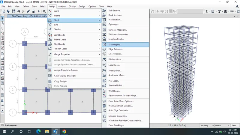
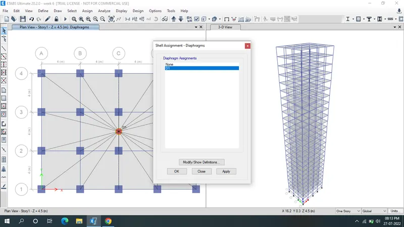
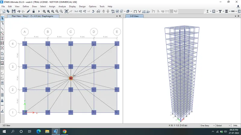
- Click the run Analysis.
- Result will shown below.
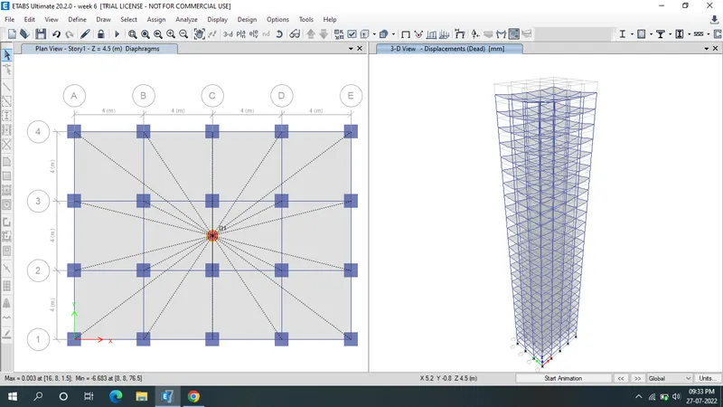
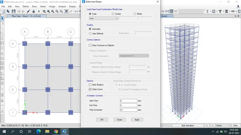
- Deformed shape of live load.
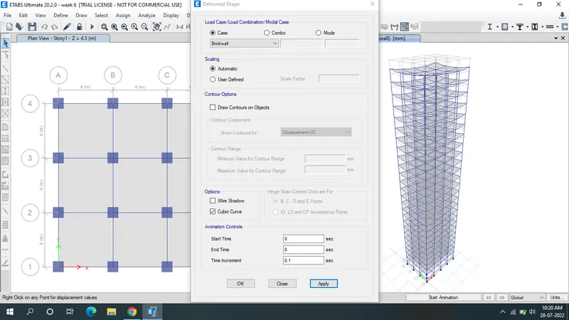
- Deformed shape of brick wall.
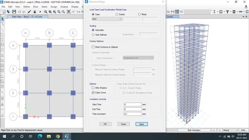
- Deformed shape of EQX
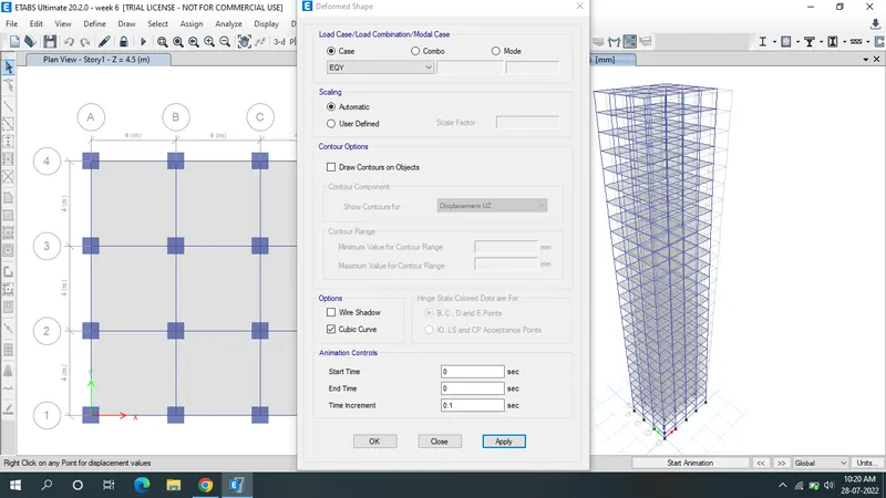
- Deformed shape of EQY
Modal participating mass ratios
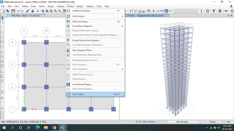
- Click the "Display" & select show tables.
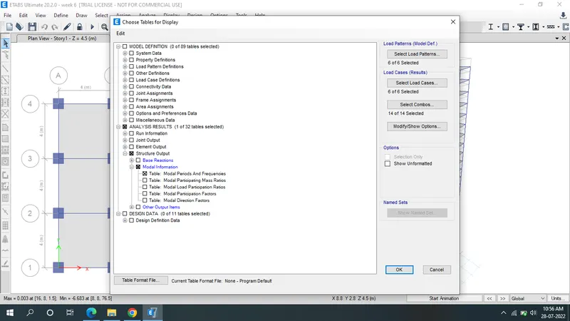
- click the structural output>Modal information>Modal periods & frequencies.ok
Carry out the following exercises:
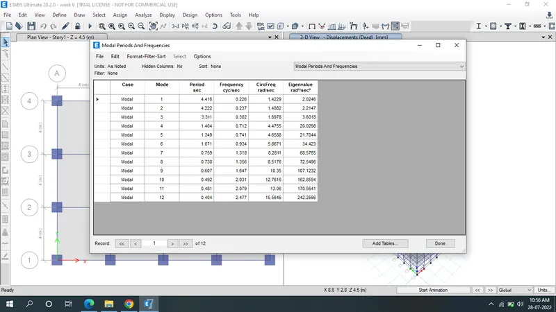
- Check if the translational fundamental natural period of vibration in both the x and y direction is approximately: TX1= 4.4 second Ty1= 4.2 second
- Yes:As table results shown Model1=4.416 & Model2=4.222.
Torsional irregularity
- Check if the following provision in Table 5 of IS 1893 (part 1) – 2016, on torsional irregularity satisfied
Yes : Torsional mode time period should be lesser than X & Y directiion time periods.
Vertical irregularity
The natural period corresponding to the torsional mode of oscillation must be less than the two fundamental translational modes of oscillation along each principal plan directions.
- Check if the two provisions of clause 7 in Table 6 (shown below) of IS 1893 (part 1) – 2016, regarding vertical irregularity is satisfied
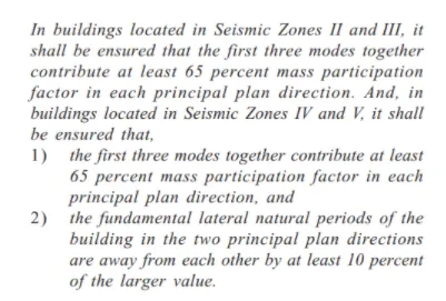
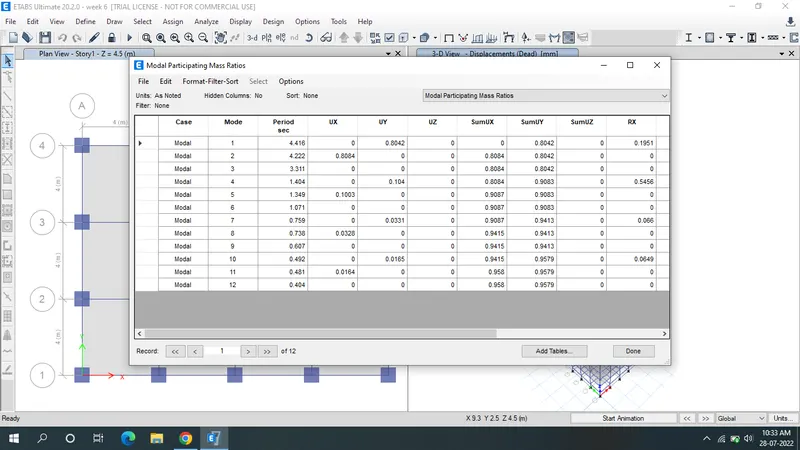
- 25 storey structure is located in seismic zone 3 & modal participating mass ratio in
X direction=0.804+0.1003+0.0328=0.9371=93%
Y direction=0.8042+0.104+0.0331=0.9113=91%
Hence it is satisfied.
- Fundamental lateral natural periods in two principal plane directions are away from each other by at least 10%=NO.
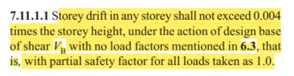
- Check if provision on inter-storey drift limitations in clause 7.11.1.1 satisfied. Please note that this check is for Serviceability Limit State and hence is for situation when stucture is subjected to unfactored seismic base shear
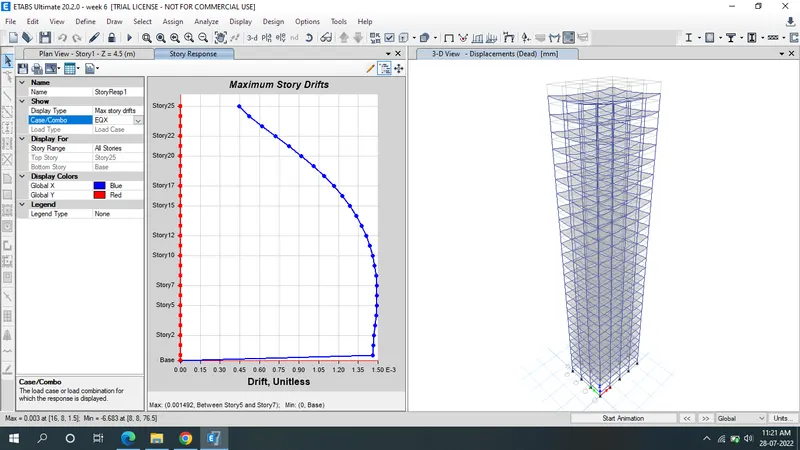
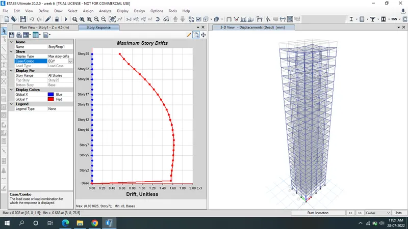
- EQX is the 1.46.
- EQY is the 1.56.
- It is not near 4 hence it is Ok.