Modelling of 25 storey building with the specified properties using ETABS
Challenge 6 – ETABS modelling of a 25 storey building
Model a 25 storey building on ETABS with structural properties as specified below. Ground floor or plinth floor level can be taken at a height of 1.5 metres from the base. Each of the successive 25 storeys has a storey height of 3 metres.
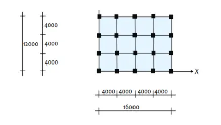
Structural Element Sizes
- Beams : 300 × 400 mm
- Columns : 800 × 800 mm
- Slab : 150 mm thick
Material Properties
- Grade of Concrete : M30
- Grade of Steel Reinforcement Bars : Fe 415
Loading
- Dead Load on beams from infill wall : 10 kN/m (Let us assume the same for roof floor in view of parapet)
- Live load on floor : 3 kN/m2 (Let us assume the same for roof floor)
a) Buildings are assumed to be pinned at the base
b) All columns in all storey are of the same size
c) All beams in all storeys are of the same size
d) Building is located on Soil type-II and in Zone-III. Assume other factors if required.
Carry out the following exercises:
- Check if the translational fundamental natural period of vibration in both the x and y direction is approximately:
T x 1 T y 1
This check will help confirm if modelling is done correctly. Some deviations from the above values is possible (± 2%). But any major deviation will suggest an error in modelling.
- Check if the following provision in Table 5 of IS 1893 (part 1) – 2016, on torsional irregularity satisfied:
The natural period corresponding to the torsional mode of oscillation must be less than the two fundamental translational modes of oscillation along each principal plan directions.
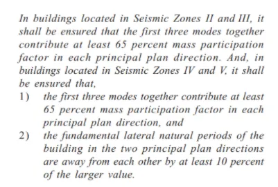
- Check if the two provisions of clause 7 in Table 6 (shown below) of IS 1893 (part 1) – 2016, regarding vertical irregularity is satisfied
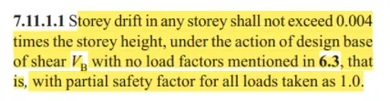
- Check if provision on inter-storey drift limitations in clause 7.11.1.1 satisfied. Please note that this check is for Serviceability Limit State and hence is for situation when stucture is subjected to unfactored seismic base shear
ANS :
AIM : To model and analyze a 25 story building with given specifications and to cross the check the parameters as per Code IS 1893 (Part 1 ) whether satisfied or not
PROCEDURE :
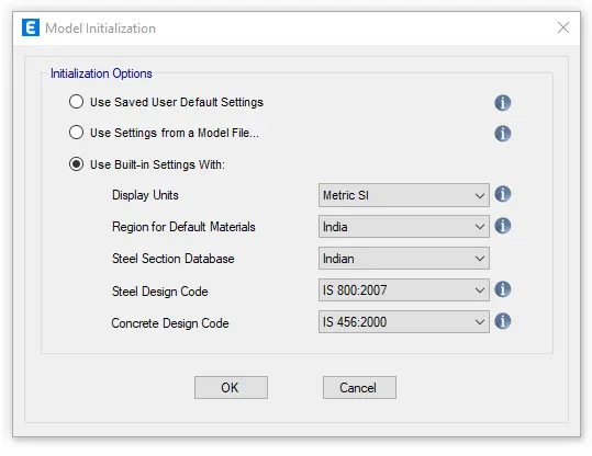
Step 1 : Open then Etabs software and click on new model, the model initialization dialogue box will appear in that select use Built-in settings with and make the settings accordingly and press ok
Step 2 : New model quick template dialogue box will appear
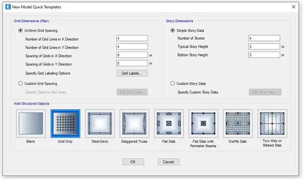
In the above dialogue box select custom grid spacing in grid dimension and select custom story data in story dimension
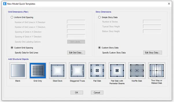
In custom grid spacing click on edit grid data you will get the grid system data dialogue box
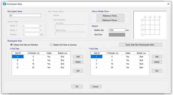
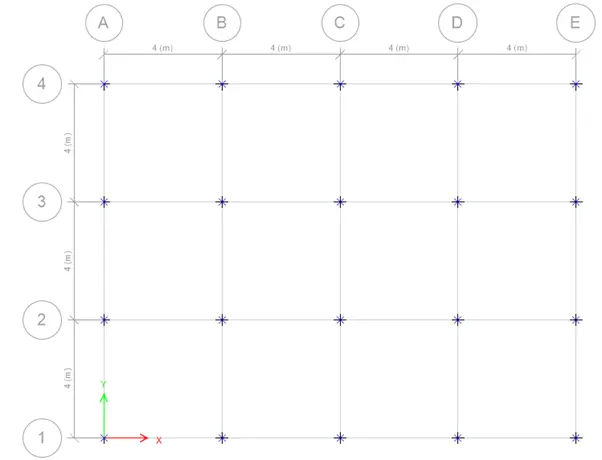
Give the data according to the question given in both x and y direction
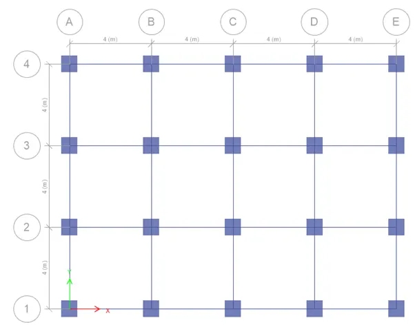
As per the question the spacing between the grids is 4m in both x and y direction and give other data accordingly and press ok
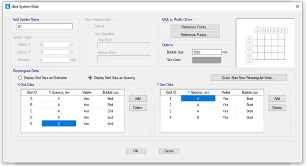
In custom story data click on edit story data you will get the story data dialogue box
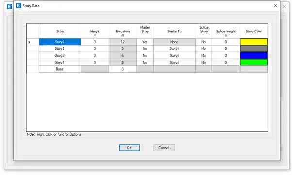
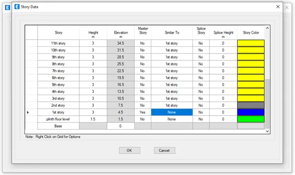
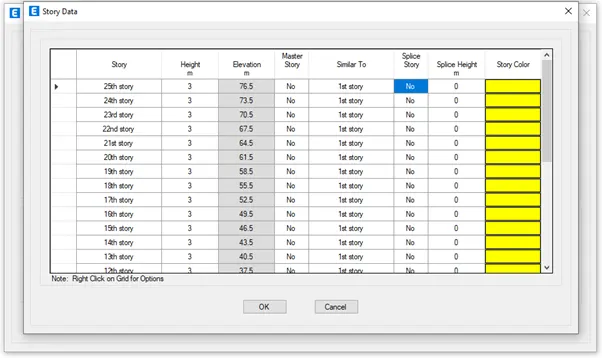
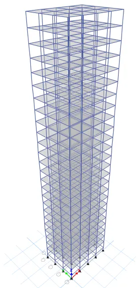
Add up to 25 story with each story height as 3m and base to plinth floor level as 1.5m as per the given question
Give the master story as first story and for other story give similar to as first story
By right clicking the arrow given in top row add the required amount of story and do the settings accordingly and press ok
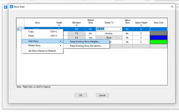
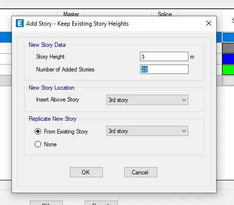
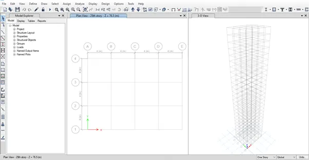
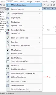
Step 3 : Go to define tab and select material properties
Add grade of concrete as M30 and Grade of steel reinforcement bars as Fe415 and do the settings accordingly for each material
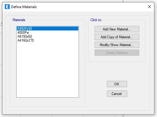
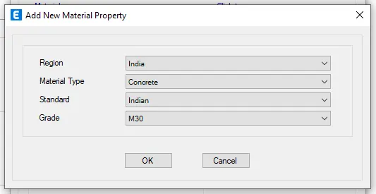
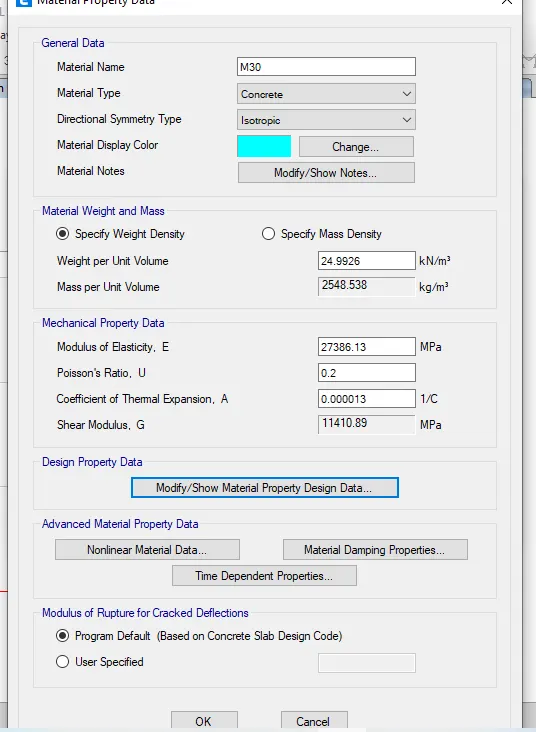
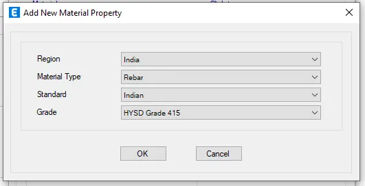
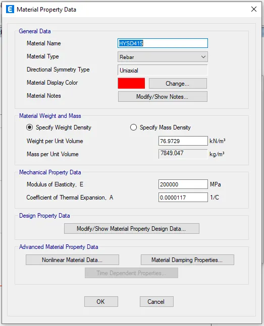
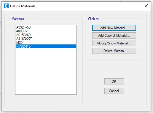
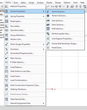
Step 4 : Go to define tab and select section properties in that select frame sections
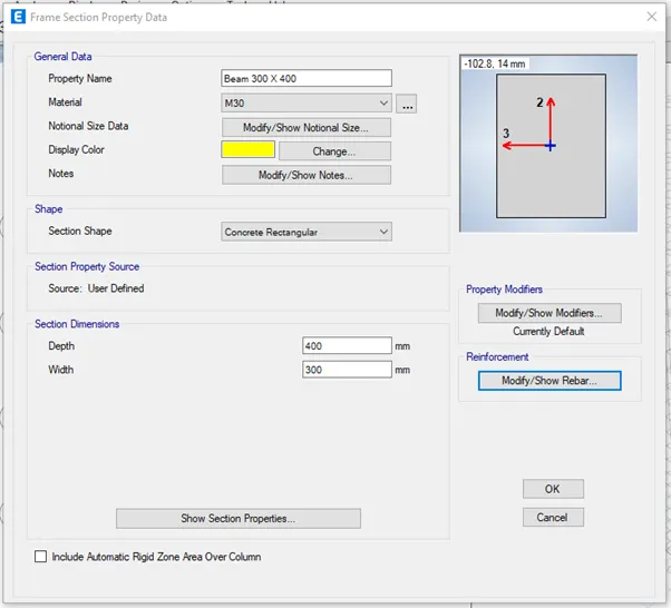
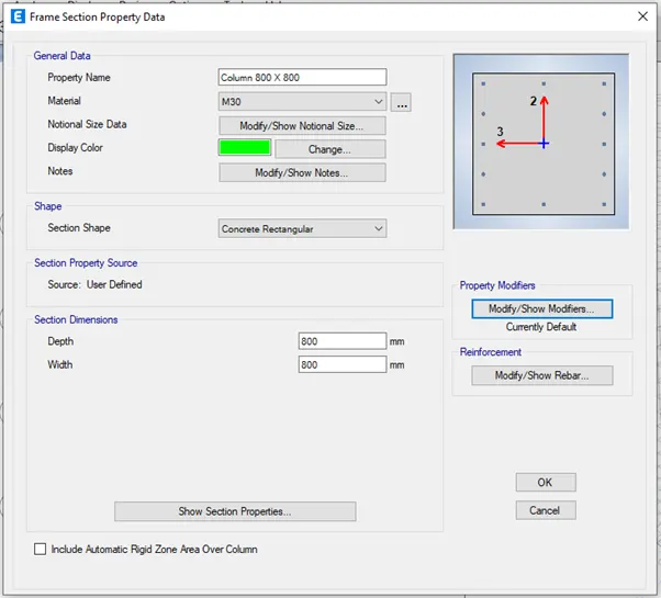
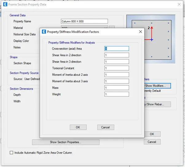
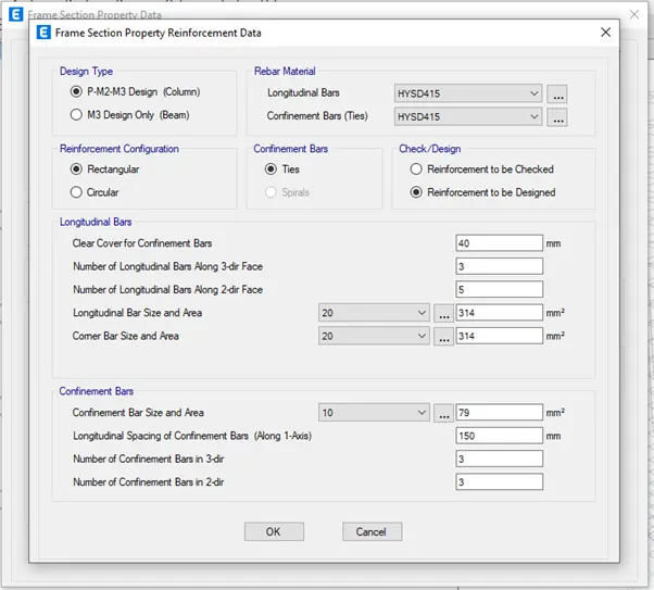
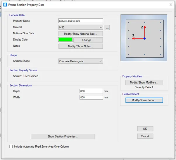
Add beam of size 300 x 400 mm and column of size 800 x 800 mm properties as per the question by clicking on Add new property
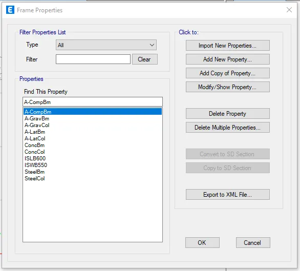
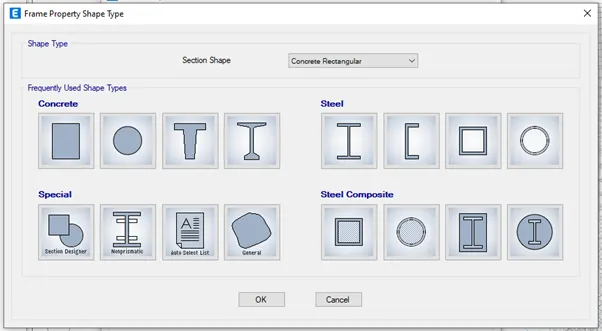
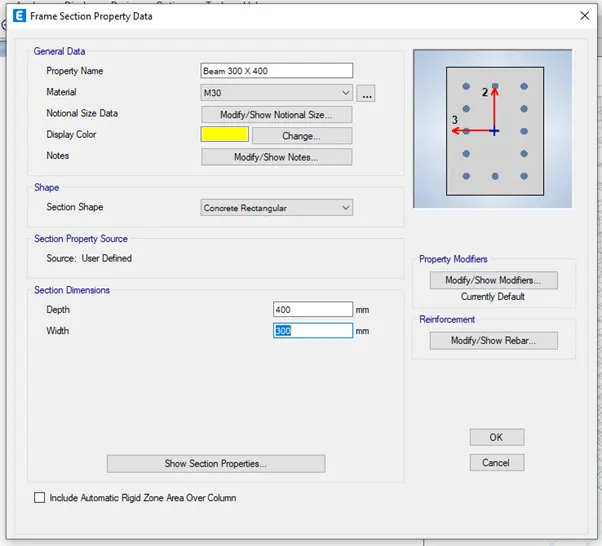
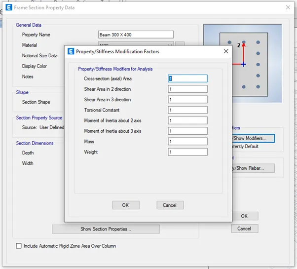
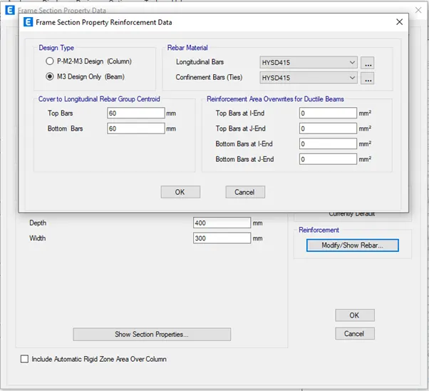
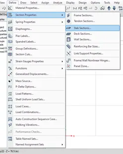
Go to define tab and select section properties in that select slab sections
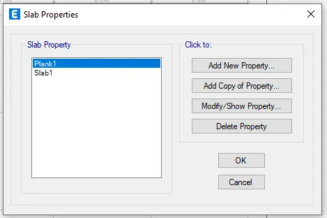
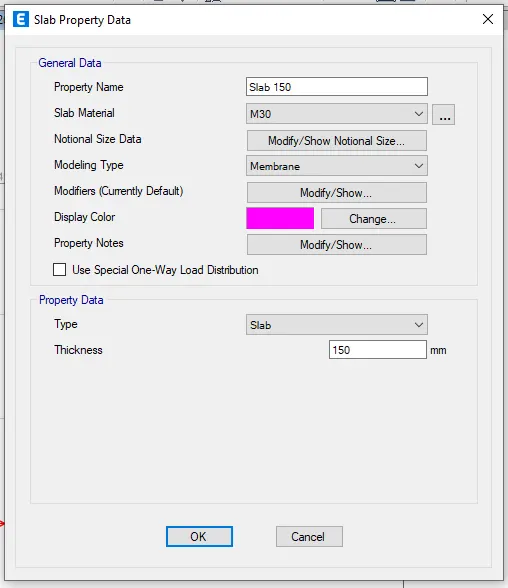
Add slab of 150mm thick as per the question by clicking on Add new property
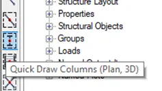
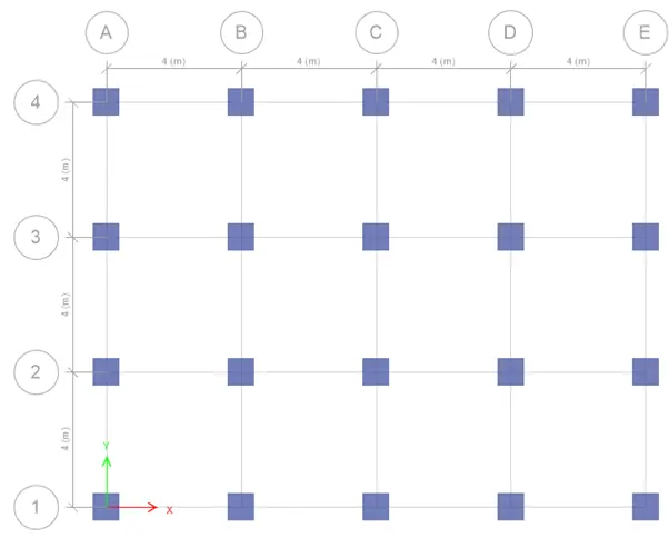
Step 5 : Draw the column 800 x 800 at each intersection of the grid by selecting Quick draw column and keep it as all stories

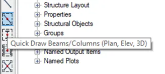
Draw the beam 300 x 400 at grid line by selecting Quick draw beam and keep it as all stories
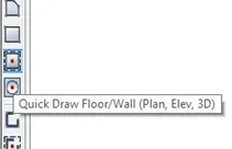
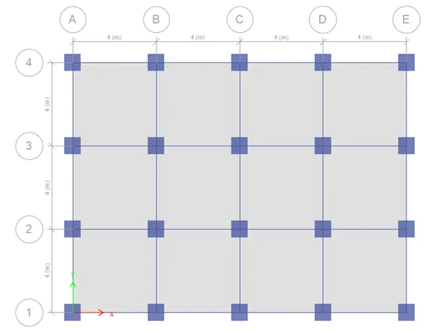
Draw slab of 150mm by selecting quick draw floor and keep it as similar stories
Step 6 : Go to base and select all the joints
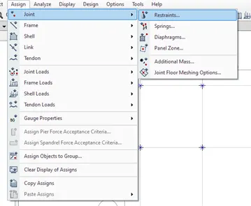
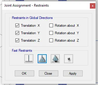
Go to assign tab select joint in that select restaints and select pinned support for all the directions and click on apply
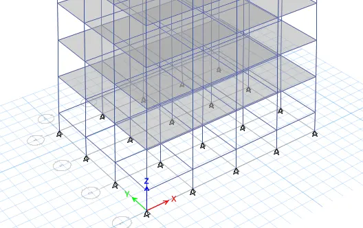
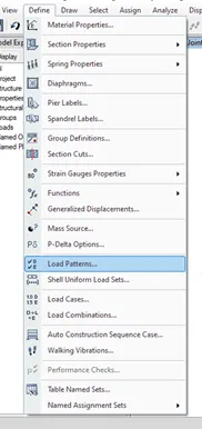
Step 7 : Go to define and select the load pattern
Add the loads like dead load, live load, brickwall load and earthquake load both in x and y direction in positive and negative direction
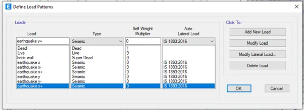
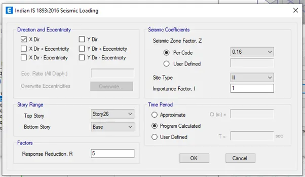
Click on modify lateral load of all earthquake loads, set a range from base to 25th story, seismic zone factor as 0.16, importance factor as 1, site type as II and time period as program calculated
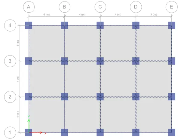
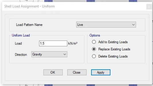
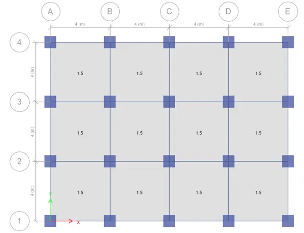
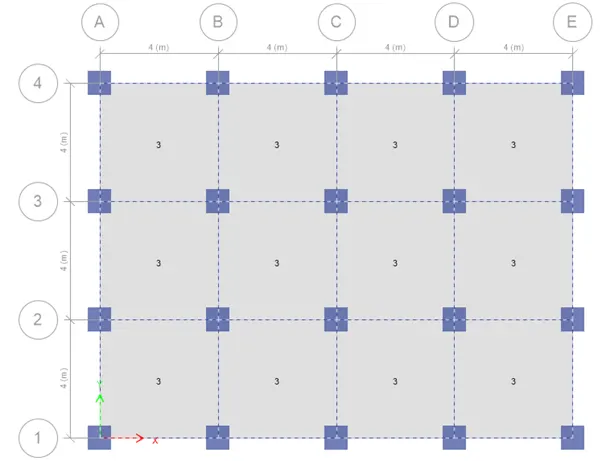
Step 8 : Assign live load to all the 25 story
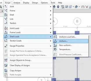
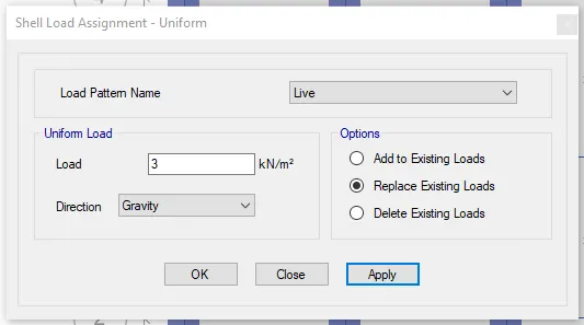
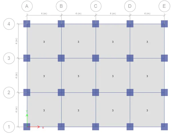
From first story to 24 th story give the slab loadas 3KN/m^2 and for 25 th story which is roof of the building give live load as 50% of the live load
By selecting the slabs go to assign tab and select shell load and do the settings accordingly and click apply
Step 9 : Assign brick wall load to all the 25 story
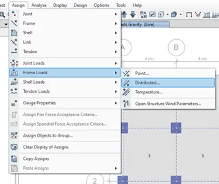
Give the brick wall load as 10KN/m for all the stories
By selecting the beams go to assign tab and select frame load and do the settings accordingly and click apply
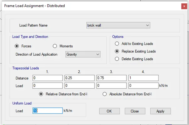
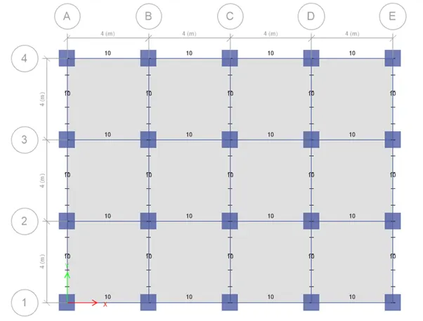
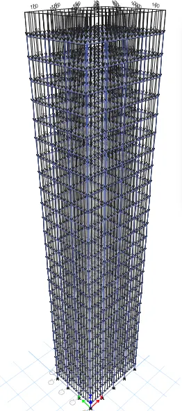
Step 10 : Go to define tab and select mass source and modify the mass source
Add the required load and assign the load to the model
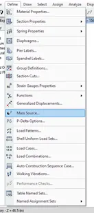
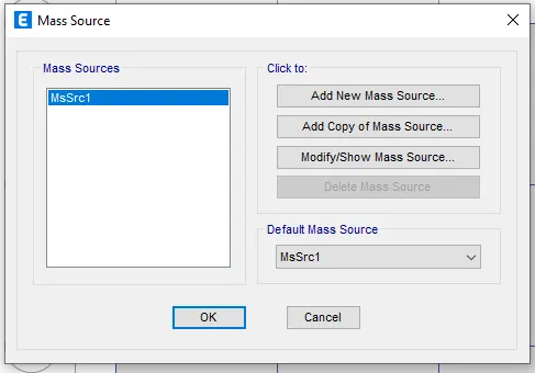
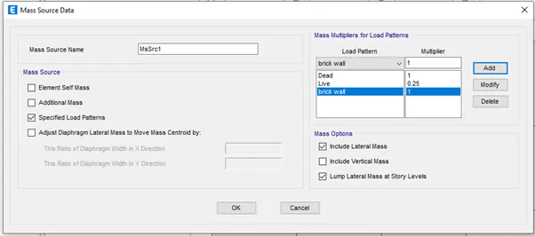
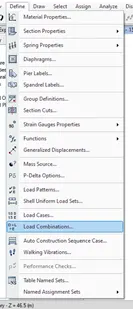
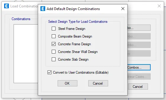
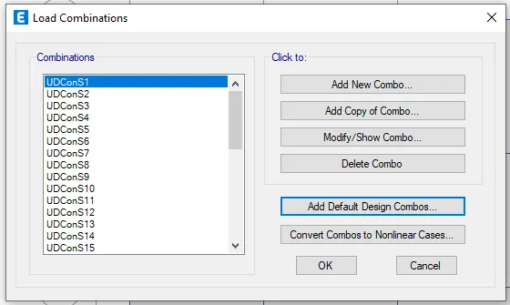
Step 11 : Go to define tab and select load combinations in the dialogue box click on add defaut design combinations
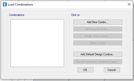
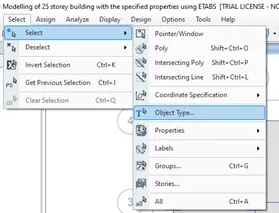
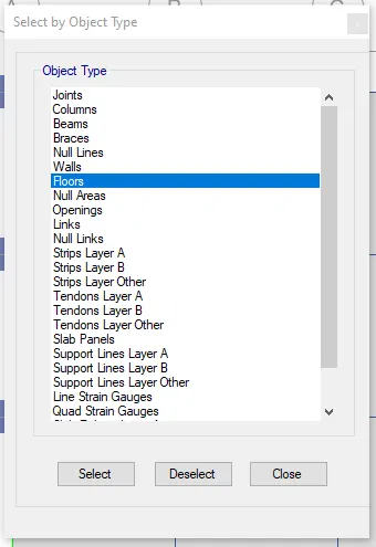
Step 12 : To create the diaphragm to the shell go to select in that select object type and in that select floors and click select and preess close
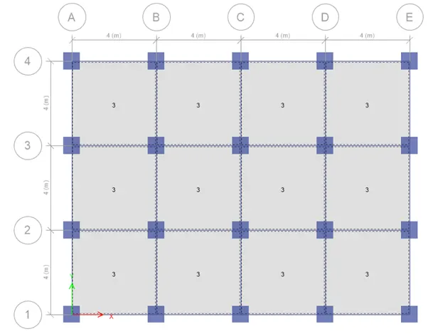
Go to assign tab select shell in that select diaphragms and select D1 and click ok
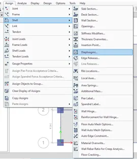
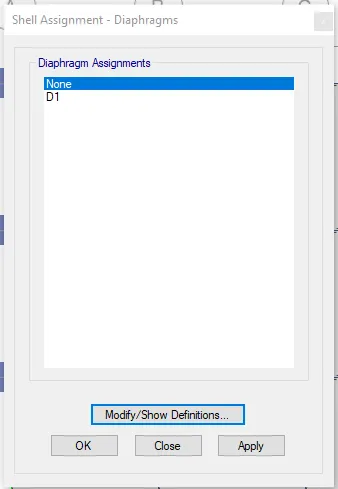
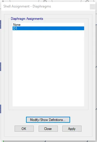
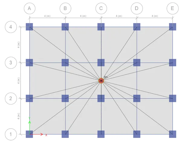
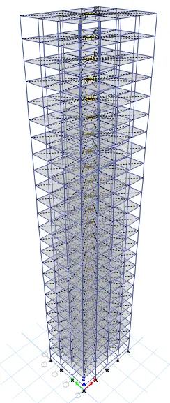
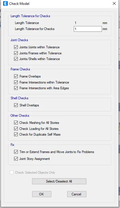
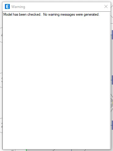
Step 13 : Go to Analyze and select check model and analyze the model for errors
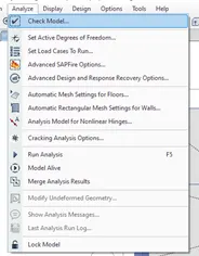
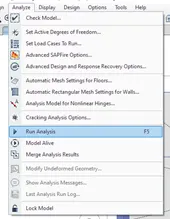
Step 14 : Go to analyze tab in that selec trun analysis the model will get analyzed and results will occur
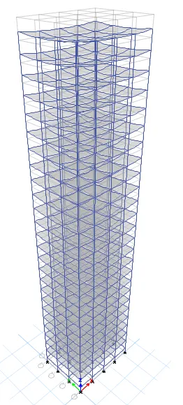
The model has been analysied
RESULT :
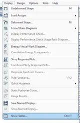
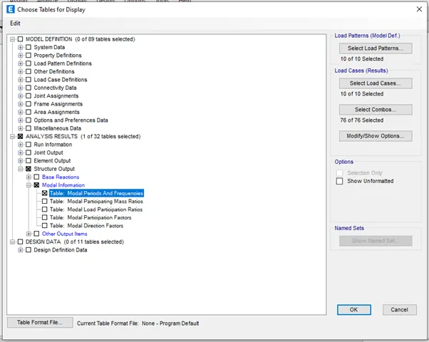
1.Go to display select show tables and select the modal periods and frequencies table and click ok
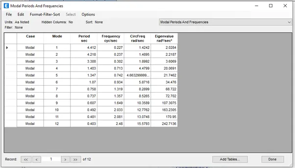
The translational fundamental natural period of vibration in x directions is Tx1 = 4.412 and in y direction is Ty1 = 4.218
2.From the above result it is clear that the torsional time period is less than the two translational time period i.e, x and y direction as per the code IS 1893-2016 Part 1 (table 5)
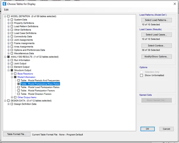
3.Go to display select show tables and select the modal participating mass ratios table and click ok
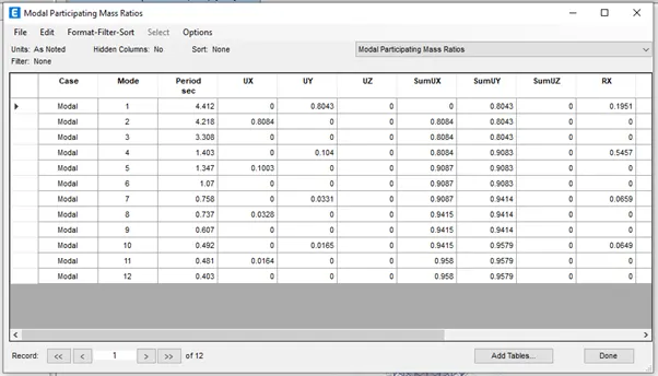
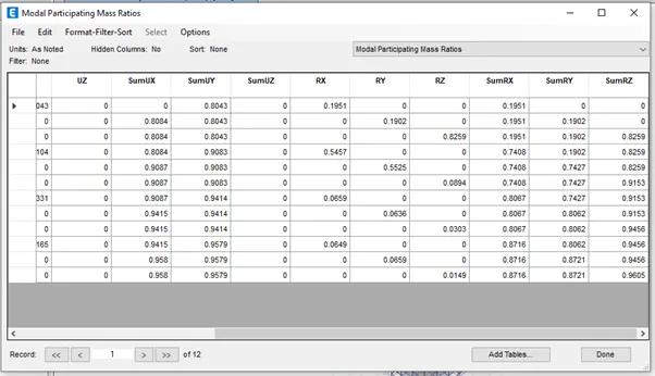
As per the above table in the first mode only the there is more than 65% of modal mass participation so it is satisified as per the code IS 1893-2016 Part 1 (table 6 clause 7)
We will take x direction time period as 4.412 by deducting 10% from this we will get 3.9708 but the y direction time period is 4.218 so this not satisified as per as per the code IS 1893-2016 Part 1 (table 6 clause 7)
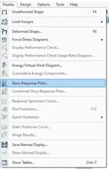
4.Go to display select story response plots
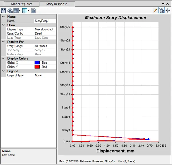
Maximum story drifts in earthquake x direction
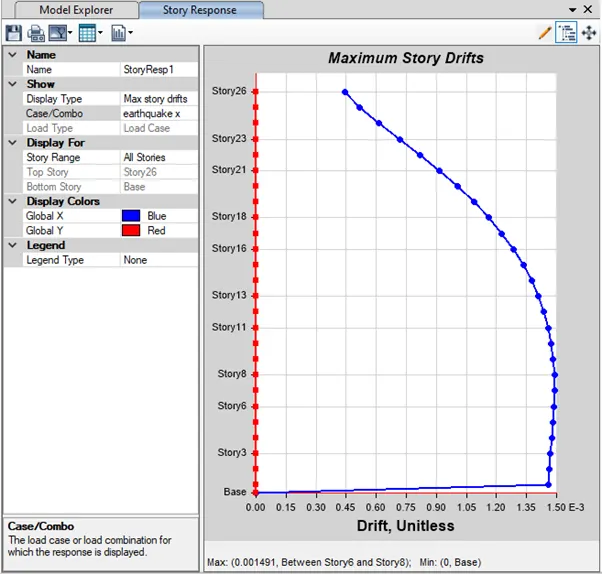
Maximum story drifts in earthquake y direction
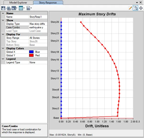
So we are getting story drifts as 1.5 in earthquake x direction and 1.7 in earth earthquake y direction so it is satisified as per IS code 1893-2016 Part 1 (clause 7.11.1.1)