Modelling of 25 storey building with the specified properties using ETABS
Ans.1.
AIM :-
To model a 25 story building using ETABS with structural properties as given in the question and also to check out the results as per given requirements from the Indian Standard codes.
INTRODUCTION :-
ETABS is an engineering software product that is used for multi-story building analysis and design. Modeling tools and templates, code-based load prescriptions, analysis methods and solution techniques, all coordinate with the grid-like geometry are all the features that are provided in etabs software to do the analysis.
PROCEDURE :-
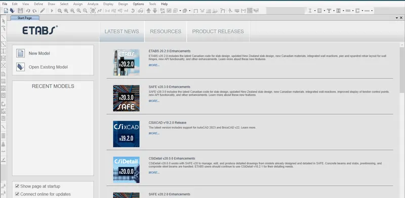
The first step involves is to open e tabs software and the interface will look like this then click on the new model option to start a new model.
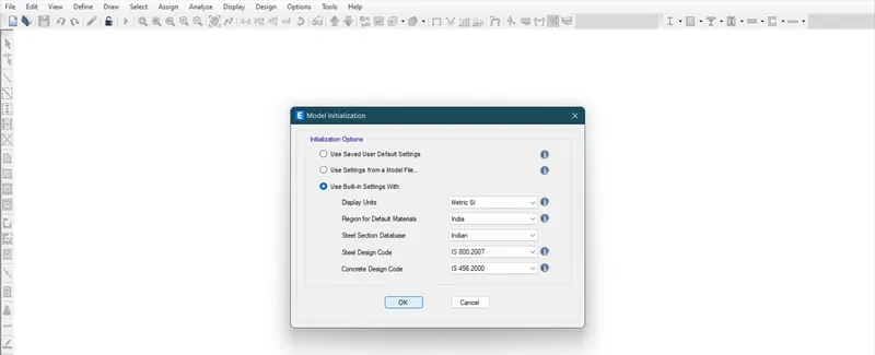
After that a new tab will open and then from there go to use building settings with option and change the setting as per the required data given in the question
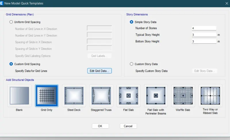
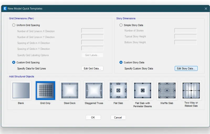
Then select the custom grading spacing and go to the edit grid data
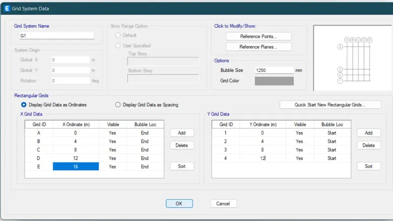
Now click on to add the grid as per the given question and mention the space between X and Y coordinates As given
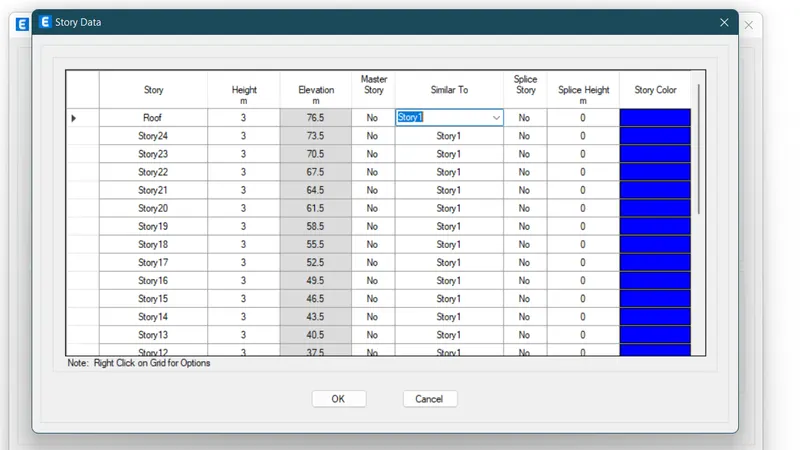
Then after doing so again go to the custom story data and go to edit story data to add new stories
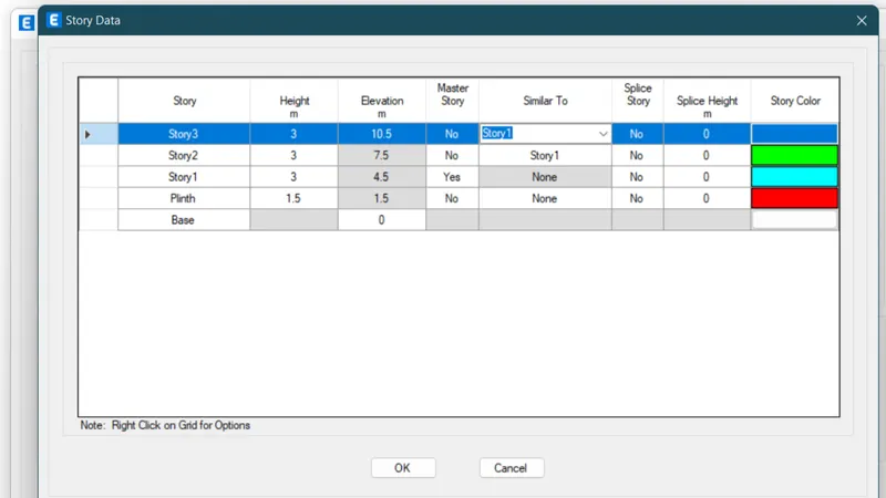
Now change the story as per your requirement and mention the height of the story. Here the after the base there is a plinth story and then we continue the story as story 1 ,2 etc.
Also make the master story as story one and other all stories as similar to Story 1
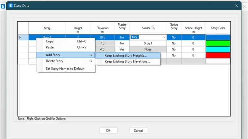
Then to add new stories just right click on the grade and click on the add story option and then select the keep existing story Heights
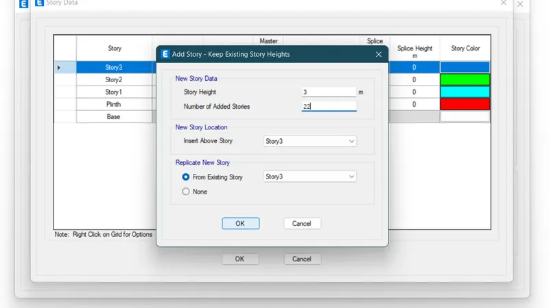
Now a story dialogue box will open where mention the height and the number of story which to be added. Here we have added 22 stories to make it 25 overall
Then make all the story similar to Story 1 and now you can see that we have also renamed the story 25 as roof and hence stories have been added
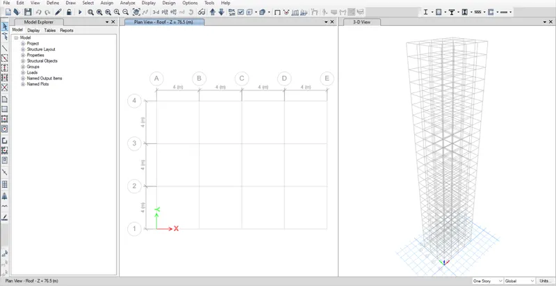
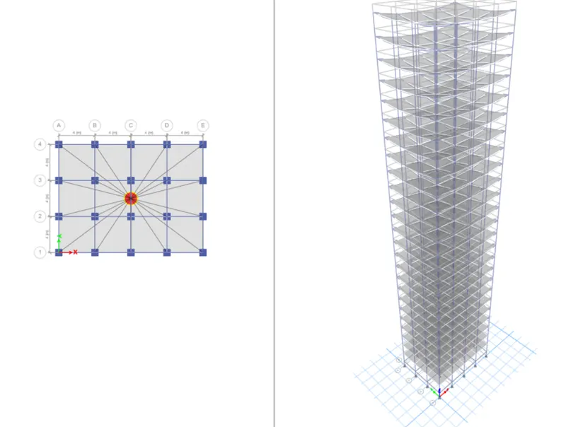
Hence our structure will look like this in 3D view
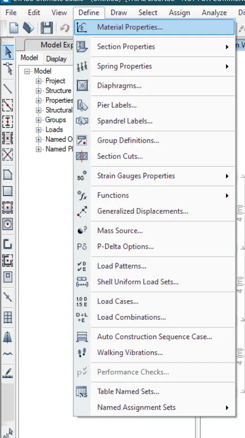
Now go to define option and then select the material properties
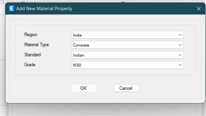
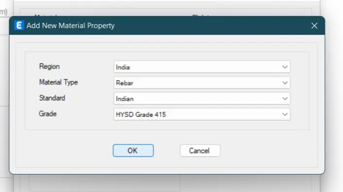
Then type the region is India and material type concrete, standard as Indian and the grade as M30
Similarly add a new Material by the same option with material type as river and grade as hysd grade 415
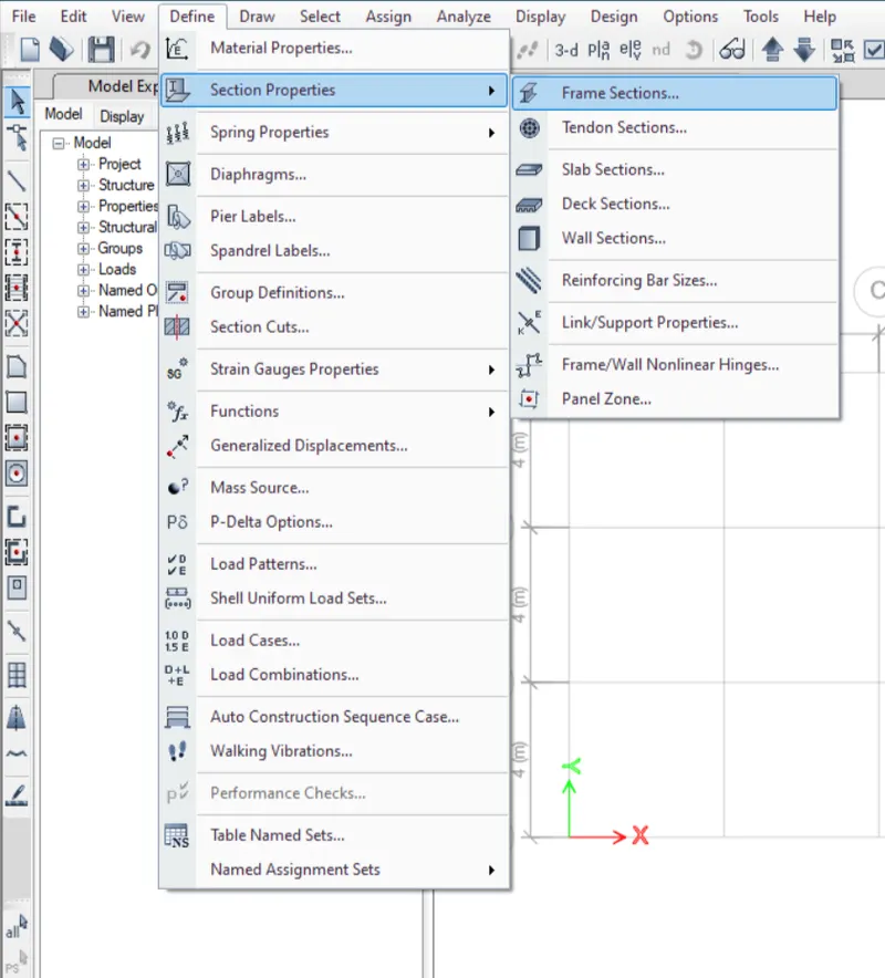
Then again go to the define option and select the selection properties then go to the frame sections to add the columns and beams properties
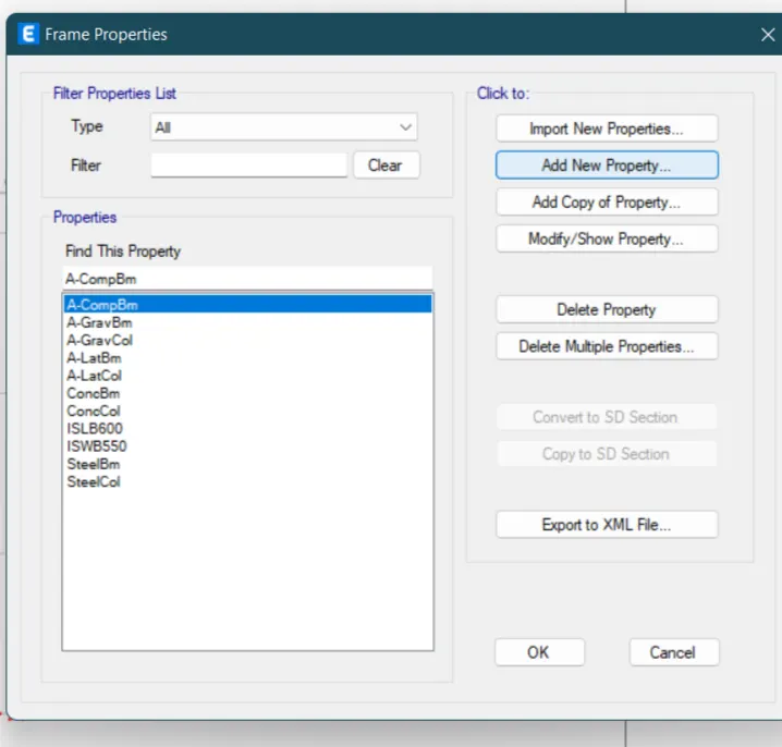
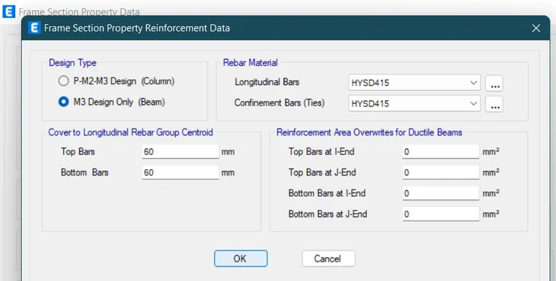
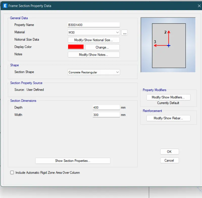
Go go to the add new property option and their select M3 design only for beam
And also river material for longitudinal and confinement bars asHYSD 415
After that click ok
Name the property name as B300x400
Material as M30
Depth as 400mm
Width as 300mm
And then click ok
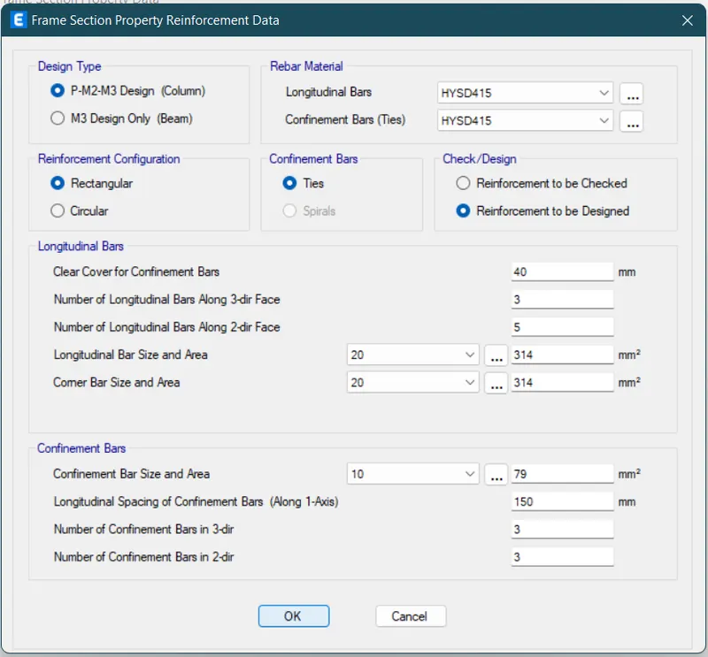
Similarly do it for column select the P-M2-M3 design for columns
click ok
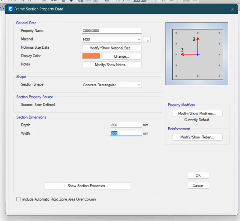
Type the property name as C800x800
Material as M30
Width and depth as 800mm
Click ok to proceed
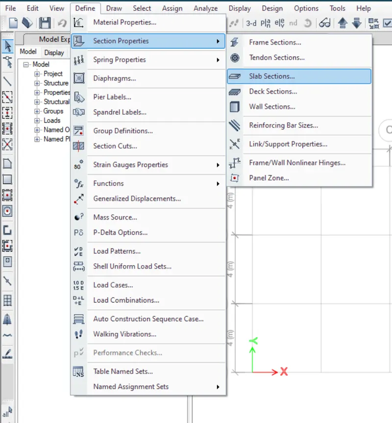
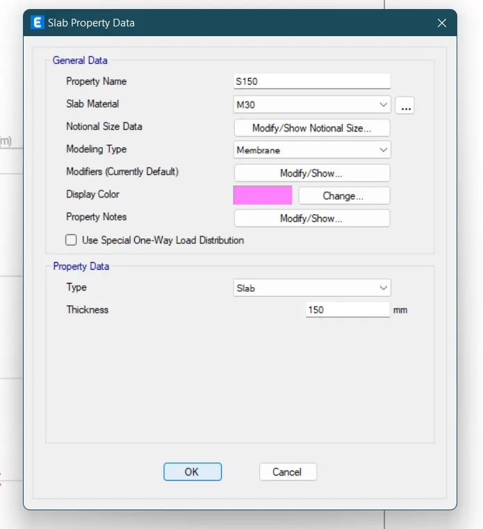
Again go to define then section properties then slab sections
Enter the slab property as per the property name as S 150 and slab material as M30 also the thickness will be 150 mm and then click ok
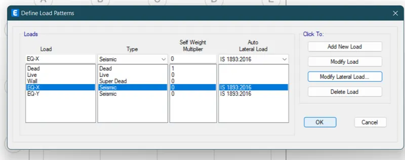
Now to assign the load patterns
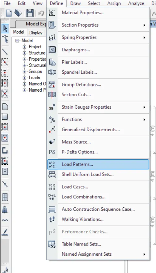
Go to define then load patterns and dialogue box will open
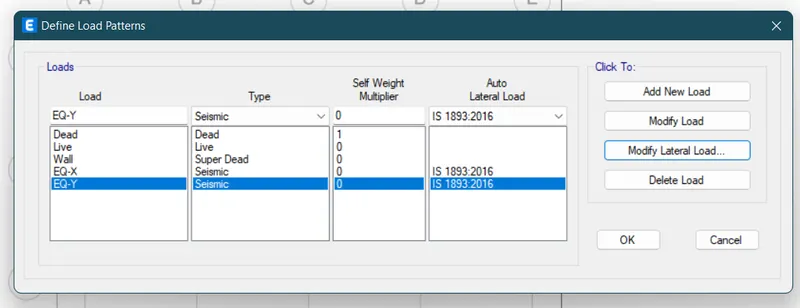
Assign the load as dead load and Live load as live type, wall load as super dead load type EQ X and EQ Y as seismic type with auto lateral load of IS 1893:2016
Then select the EQY load and click on the modify lateral load and uncheck all the box leaving the wide direction box and also change the seismic zone factor as 0.16 and click ok
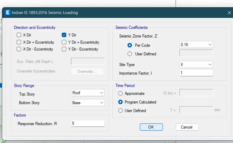
Do the same step for EQ-X
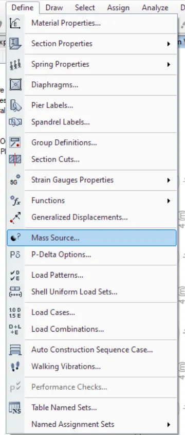
Now go to the define option again and then select the mass source to assign the mass of data
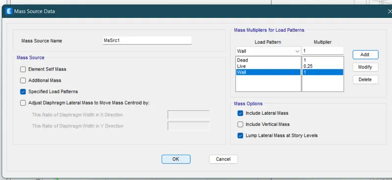
An check all the mass source and check the specified load patterns and provide the load pattern as
Dead load of multiplier 1
Live load of multiplier 0.25
And wall load of multiplier 1 and then click on ok.
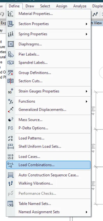
Now to add the load combinations go to the define and then go to load combination option
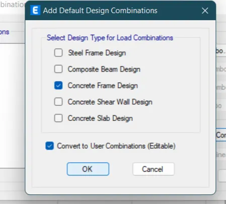
Select the concrete frame design and then also select convert to user combinations and then click ok
Now to draw the columns and beams
Click on the quick draw columns option
And then change the property from the properties of object as the assigned column property
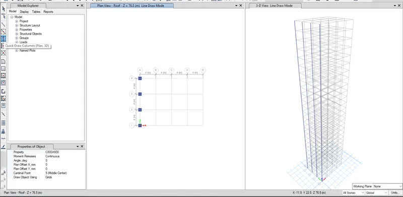
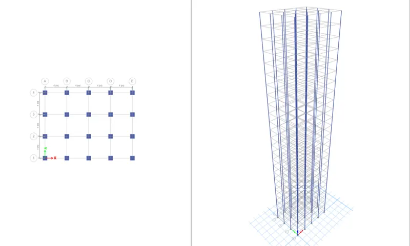
And then draw the columns on the grids
Now to draw the beams
Go to the quick draw option of colum beam
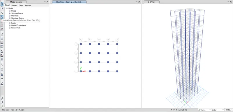
Select the property of the beam which we have assigned earlier and then draw the beams
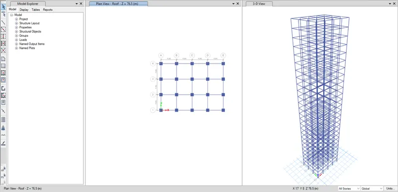
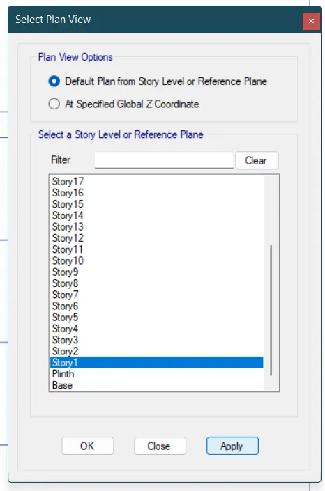
Now go to the plan view option and select the view from Story 1 and click on apply
Now to create the slab go to the quick draw floor wall option
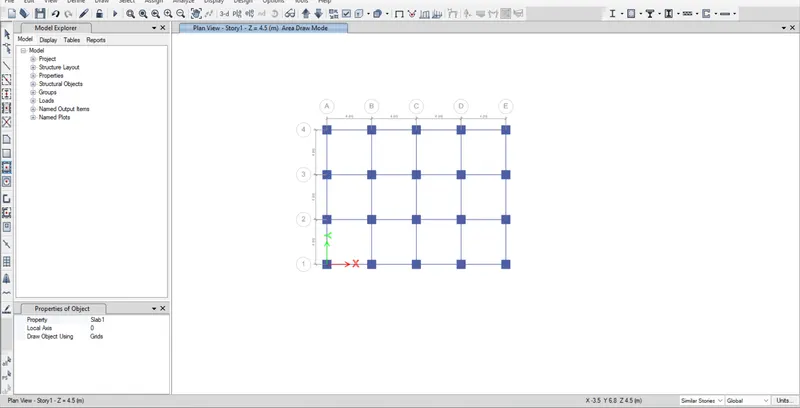
And select the property of slab as we have assigned earlier S 150
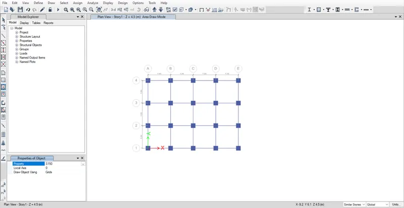
And then draw the slabs on the required plan
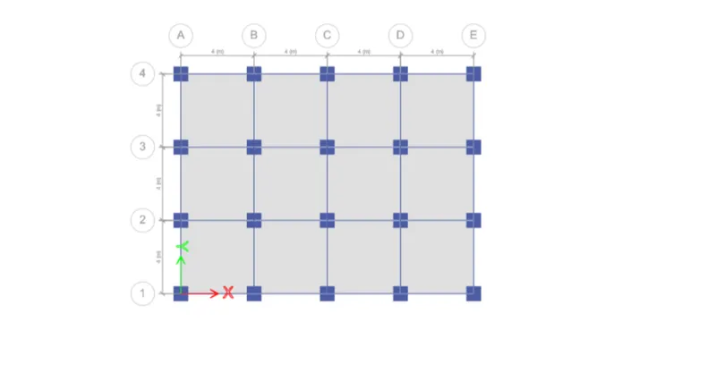
Hence labs have been created in our model will look like this
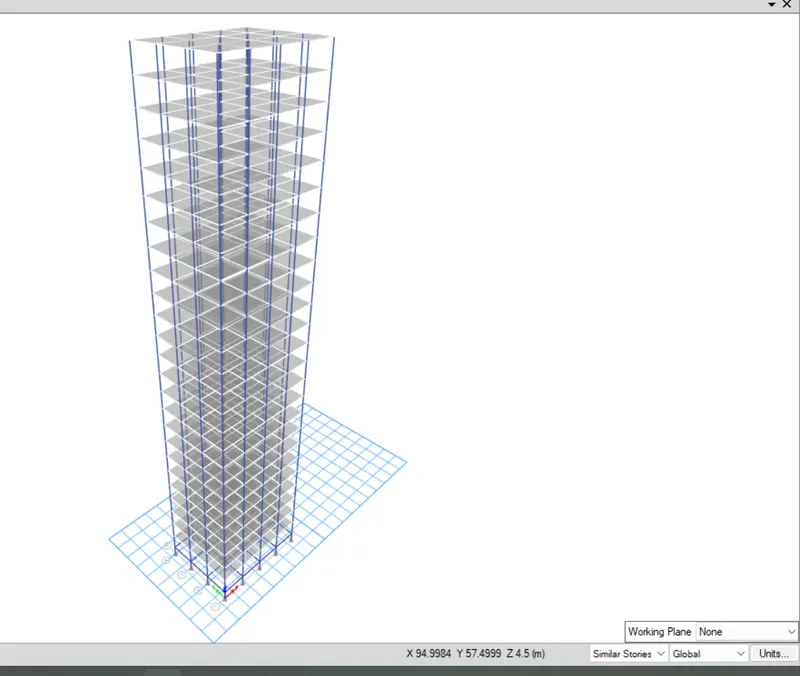
Now to add the loads
First go to the select option and from there go to properties and then frame sections
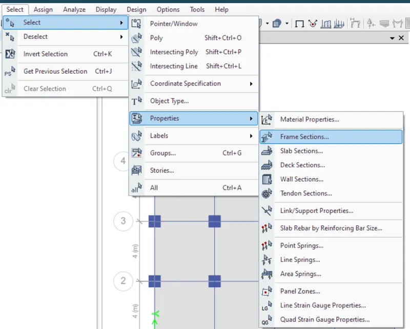
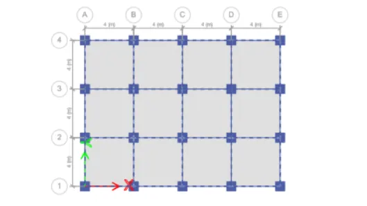
Hence all the beams are now selected
Then go to the Sion option then frame loads and then distributed
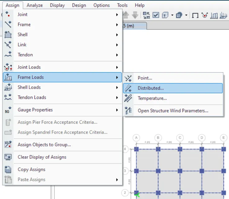
Dialogue box will open from where enter the load pattern name as wall and type the uniform load as 10kn/m
And then click on apply
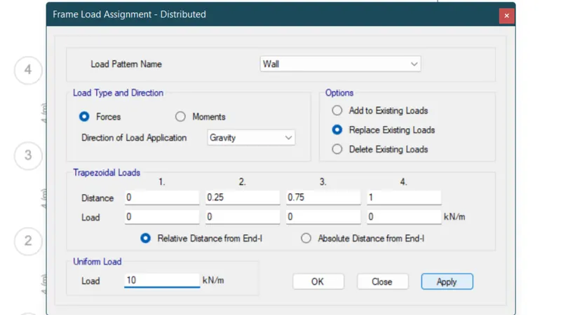
Here you can see that the load has been assigned
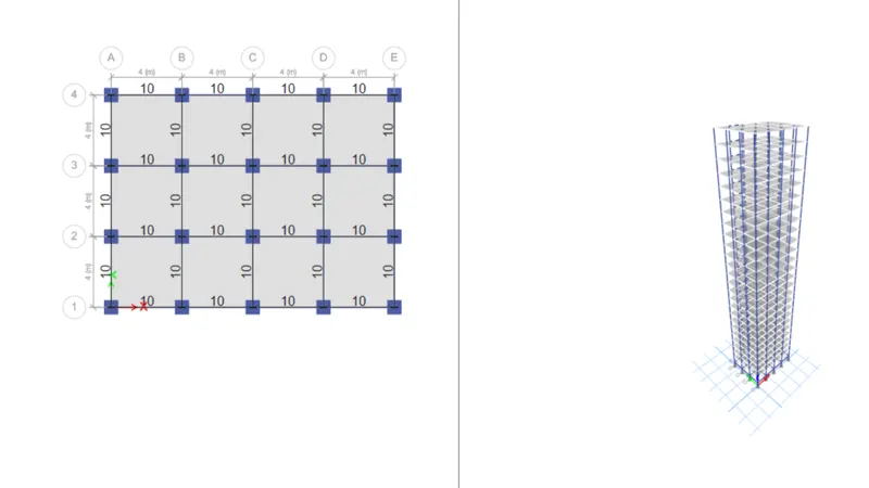
Now to assign the load for the slabs
Go to select then properties then slab sections
Then select the slab which we have assigned earlier as S150.
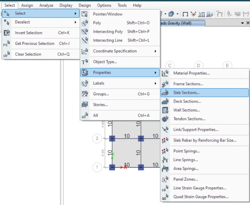
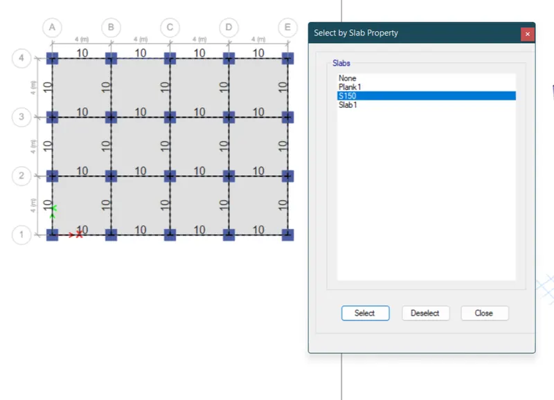
Now to assign the shell loads go to assign then shell loads and then uniform
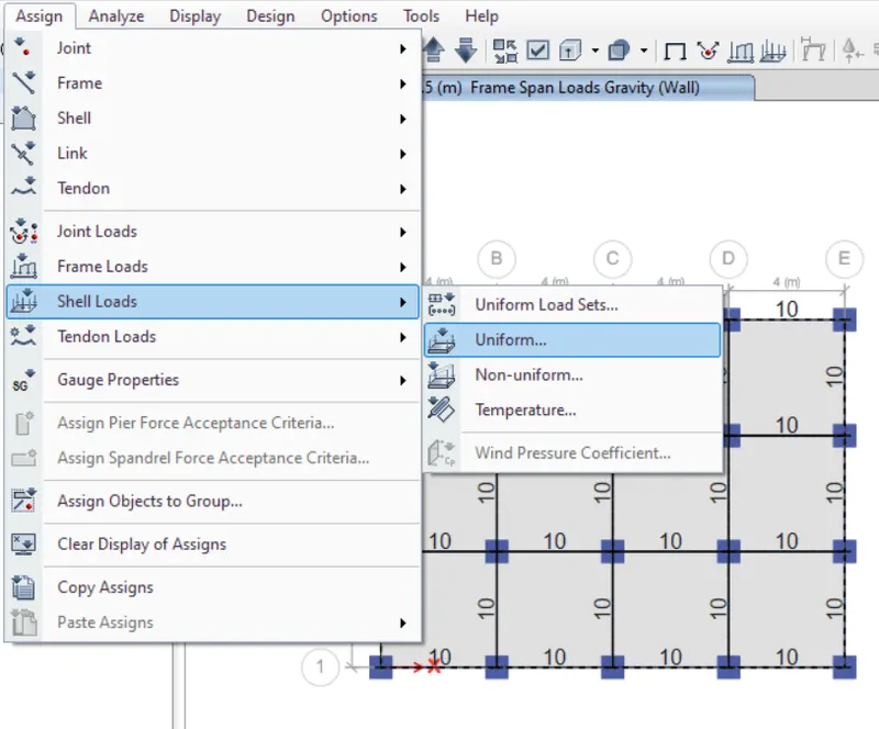
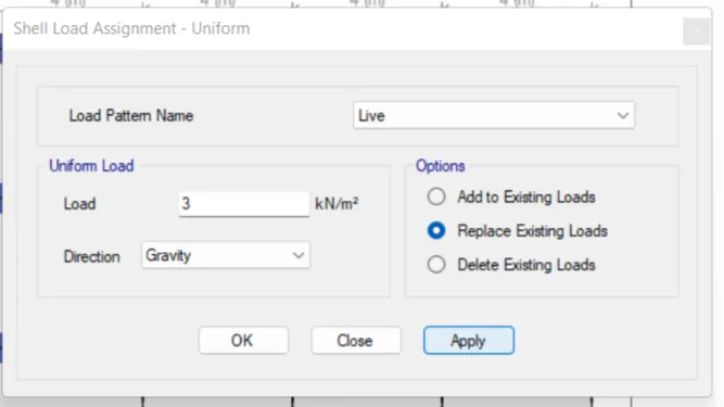
Now you can see that new dialogue box have been opened
Select the load pattern as Live
And type the load as 3 Kn/m2
Then click on apply
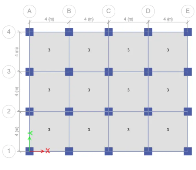
Hence the load have been applied to our slab
Now to assign the Diaphragm
Go to assign then shell then diaphrams
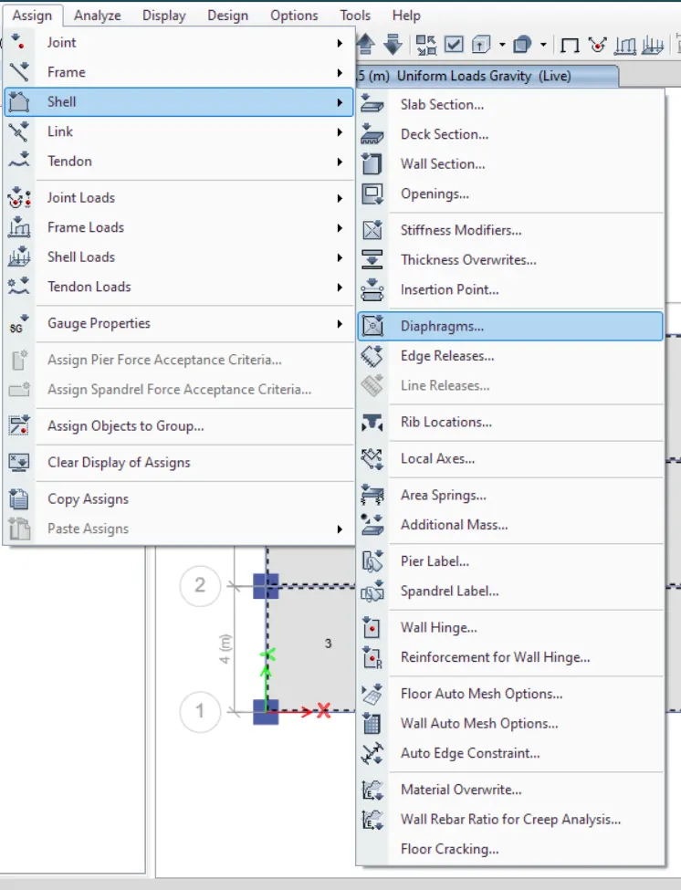
Then select the diaphragm as D1.
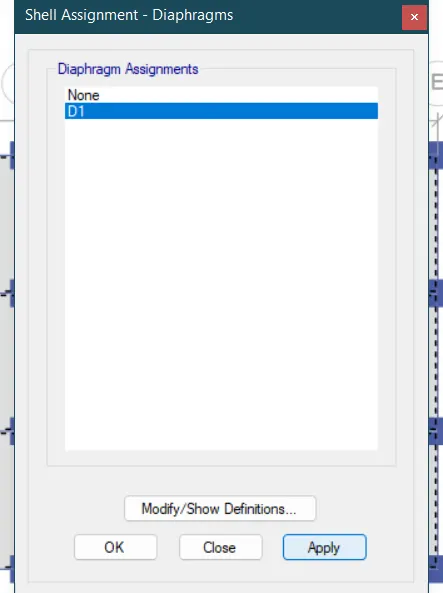
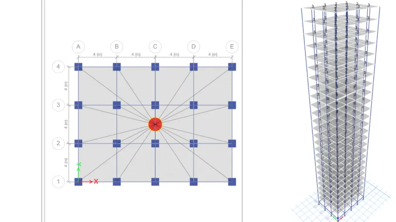
Hence the diaphragm has been created in our model
Now after everything has been assign to our model its time to run the analysis for our model
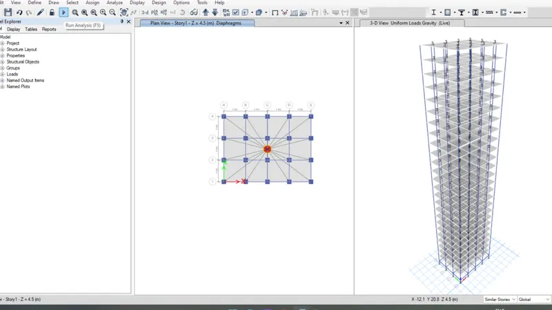
Once the analysis have been completed the model will look like this and the reports are also been provided in the model Explorer tab where you can check out the result for the model we have created
RESULT :-
1. For the fundamental translation natural period
In X direction we got - 4.41 Sec
In Y direction we got - 4.22 sec
Which is almost similar to 4.4 and 4.2 second
2.Torsional irregularities
As per IS 1893-2016(part1) table 5
We got ,
torsional mode time period = 3.311
3.311 is lesser than 4.416 , 4.22
so torsional mode time period is lesser than X and Y direction time periods
3. Vertical irregularity
As per IS 1893-2016(part1) table 6 , clause 7
In modal participation the first mode and the second mode participation percentage are 80.84% and 80.42% , so there is no need to add the second and third modes for X and Y direction because in the first mode only the condition is satisfied.
Also it is given that the fundamental lateral periods in two principle plane directions are away from each other by at least 10%
But here in our model we got the difference as lesser than 10% so it is not possible in our model
4 interstory drift :-
As per IS 1893-2016(part1) clause - 7.11.1.
Story drift shall not exceed 0.004 times the story height for the base share with no load factors
We get the maximum story drift for EQ X as around 1.4 to 1.6
And the max.Story drift for EQ Y as around 1.5.to 1.75
Hence it is not near the given value as per IS code, so it is also satified.