Modelling of 25 storey building with the specified properties using ETABS
AIM & INTRODUCTION :
AIM :
- To create a Model of 25 storey building on ETABS with structural properties as specified along with Ground floor or plinth floor level of height 1.5 metres from the base and each of the successive 25 storeys has a storey height of 3 metres.
INTRODUCTION :
- The E-TABS is used to create a structural building model using tools in it.
- Here, in E-TABS the deflection of the building due to the many load can be identified.
- All the properties of the Concretes and Rebars are created as per the appropriate IS CODES.
- The required load can be applied on the created Structural Model as per Soil type and Zone.
- We can Run the Analysis test over the Structural model created to analyse its performance according to the applied load.
- The Properties of the Framed and Slab Sections can be edited as per requirement.
- We can add as many number of stories required as per the requirement to analyse.
- The results can be seen in the Model information Table.
PROCEDURE :
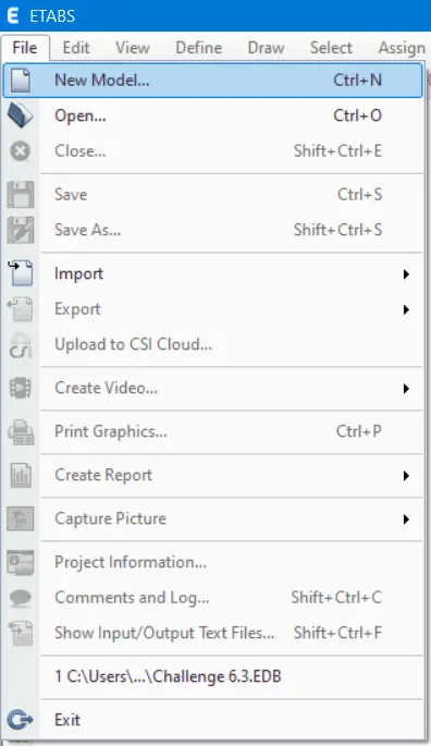
- Open E-TABS software and from File < New model .
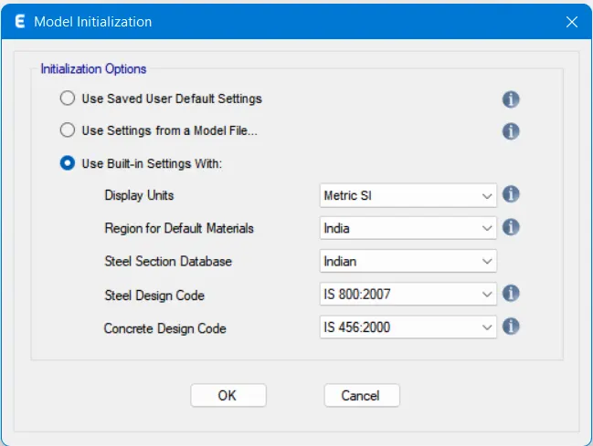
- Then from Model initialization < use built in settings with and choose appropriate.
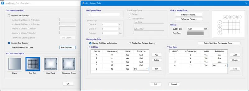
- And from New model quick templates < custom grid spacing < Edit grid data < x-grid data and y-grid data.
- In x-grids data < Grid ID < A, B, C, D, E and X ordinate < 0 m, 4m , 8 m, 12 m, 16 m.
- Likewise in y-grids data < Grid ID < 1, 2, 3, 4 and Y ordinate < 0 m, 4m, 8m, 12m.
- From the same New model quick templates < Custom story data < Edit story data.
- In story data < Story < Base, Plinth, Story1 upto story25 (the excess story will be added above the default 3 story by right clicking and adding story as shown below)
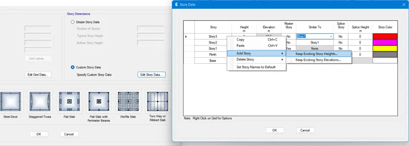
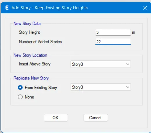
- Then in Add story < Type the Number of stories to be added above the story 3 as 22 numbers.
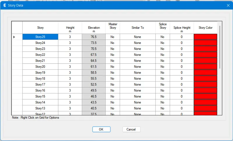
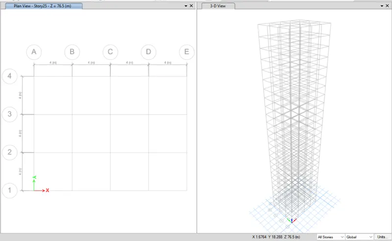
- Then the workspace will be created with 2 windows, Window-1 has 2D plan and the window 2 has 3D plan of the created 25 stories.
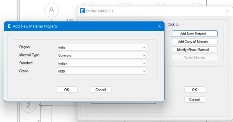
- Click and open tab Define < Material properrties < Add New Material < Region = India, Material Type = concete, Standard = Indian, Grade = M30.
- After clicking OK the Define Materials tab will be opened then click Add New Material < Material Property Data < Material name = M30, Material Type = Concrete.
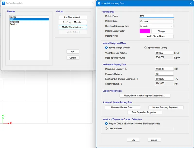
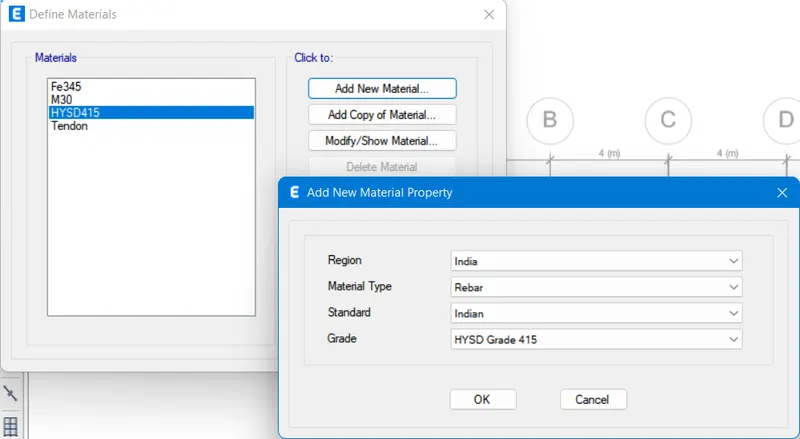
- Likewise create a Material Properties for Reinforcement such as Material Name/Type = Rebar and Grade = HYSD415.
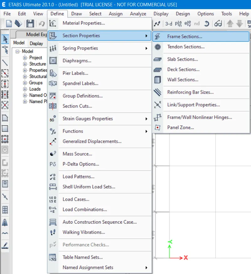
- Then to create a New Frame Properties for the " Beams " open Define < Section properties < Frame sections < Frame Properties.
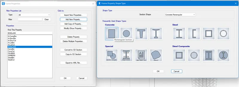
- From the Frame Properties < Add New Property < Frame Property Shape Type < Concrete .
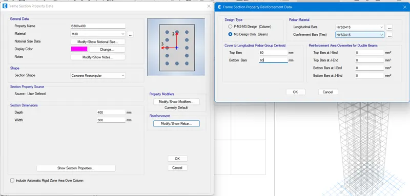
- Then the from Frame Section Property Data < Property Name = B300x400, Material = M30, Depth = 400, Width = 300 .
- From Modify/show Rebar < Frame section Property Reinforcement Data < Design Type = M3 Design only (Beam), Rebar Material = HYSD415.
- Likewise create a New Frame Properties for the " Columns " such as from Define < Section properties < Frame sections < Frame Properties.
- From the Frame Properties < Add New Property < Frame Property Shape Type < Concrete .
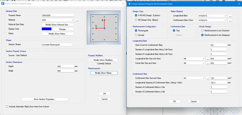
- Then the from Frame Section Property Data < Property Name = C800x4800, Material = M30, Depth = 800, Width = 800 .
- From Modify/show Rebar < Frame section Property Reinforcement Data < Design Type = P-M2-M3 Design (Column), Rebar Material = HYSD415.
- Followed by Beams and Columns, the properties for the Slab section has to be defined as below.
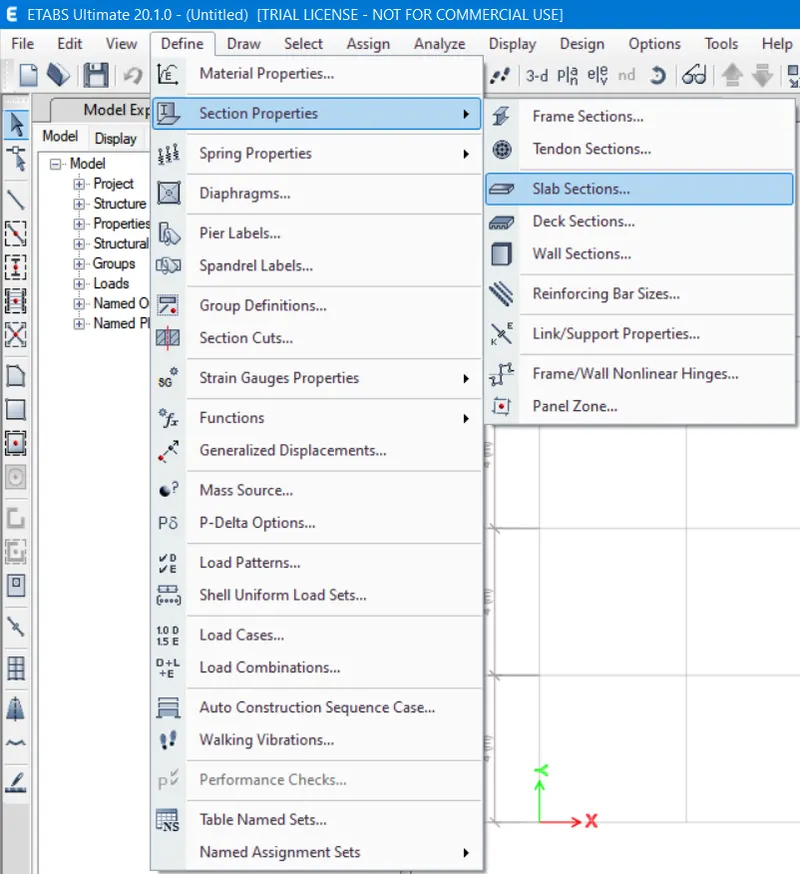
- Select and open Define < Section Properties < Slab Sections .
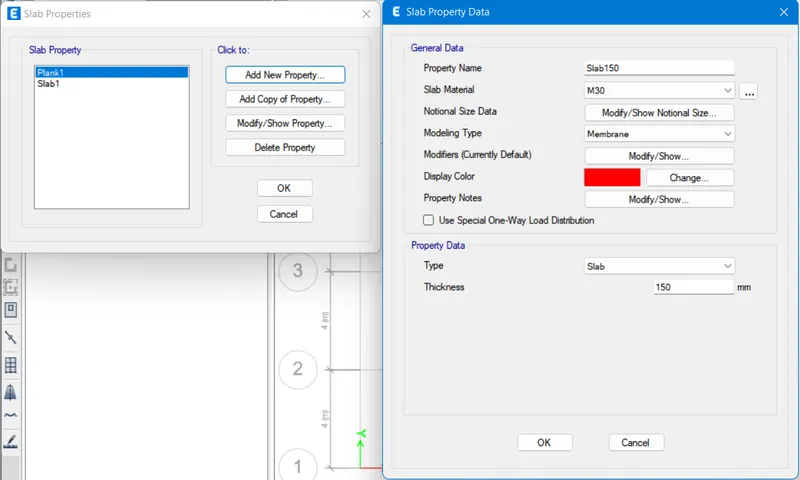
- Then the slab properties tab will be opened, from Slab Properties <Add New Property < slab Property Data < Property Name = Slab150, Slab Material = M30, Modeling Type = Membrane, Thickness = 150mm.
- The Load pattern has to be defined before mass source, by clicking and selecting Define < Load pattern < Define Load pattern.
- Then from Define Load patterns < Load, type, Self weight Multiplier and Auto Lateral load has to be defined as per IS CODE - IS 1893 2016.
1. Load name = Dead, Type = Dead, Self weight Multiplier = 0 (it can be defined in Mass source), Auto lateral load = None.
2. Load name = Live, Type = Live, Self weight Multiplier = 0 (it can be defined in Mass source), Auto lateral load = None.
3. Load name = Brickwall, Type = Super Dead, Self weight Multiplier = 0 (it can be defined in Mass source), Auto lateral load = None.
4. Load name = EQX, Type = Seismic, Self weight Multiplier = 0 , Auto lateral load = IS 1893 2016.
- Here from Load EQX < Modify Lateral Load < Indian IS 1893-2016 Seismic loading < X Dir and form Seismic coefficients < Seismic zone Factor. Z < Per Code = 0.16
5. Load name = EQY, Type = Seismic, Self weight Multiplier = 0 , Auto lateral load = IS 1893 2016.
- Here from Load EQY < Modify Lateral Load < Indian IS 1893-2016 Seismic loading < Y Dir and form Seismic coefficients < Seismic zone Factor. Z < Per Code = 0.16
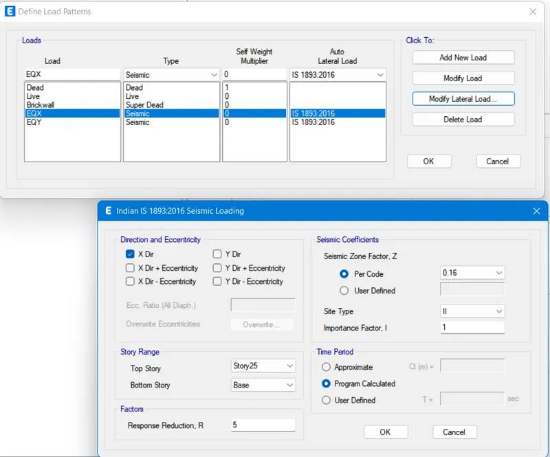
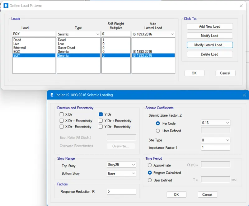
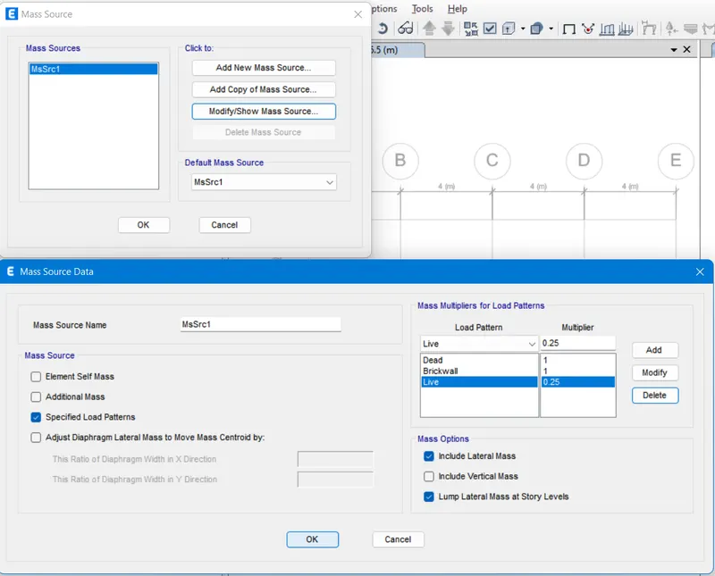
- From Define < Mass Source < Modify/show Mass source < Mass source = Specified Load Patterns, < Mass Multipliers for Load patterns.
- Then Add different load patterns with Appropriate Multipliers such as,
1. Load pattern = Dead, Multiplier = 1
2. Load Pattern = Brickwall, Multiplier = 1
3. Load Pattern = Live, Multiplier = 0.25
- Then the columns for the 25 stories should be assigned by selecting Quick draw columns Tool (icon) < Properties of object < Property = C800x800.
- And select one side corners and edges of the grids in 2D plan like in image below and we can see it will be reflecting in the 3D plan. (Note : Before assigning the Columns, Make sure the " All Stories " option is selected)
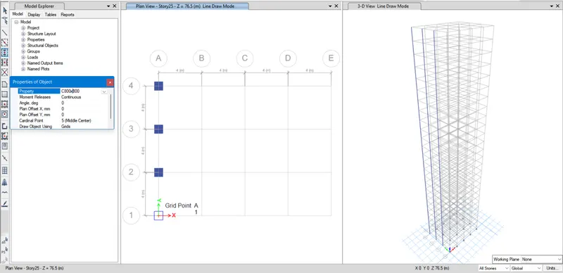
- Then Replicate the Remaining columns to all the corners and edges of the grids by selecting assigned columns through window selection.
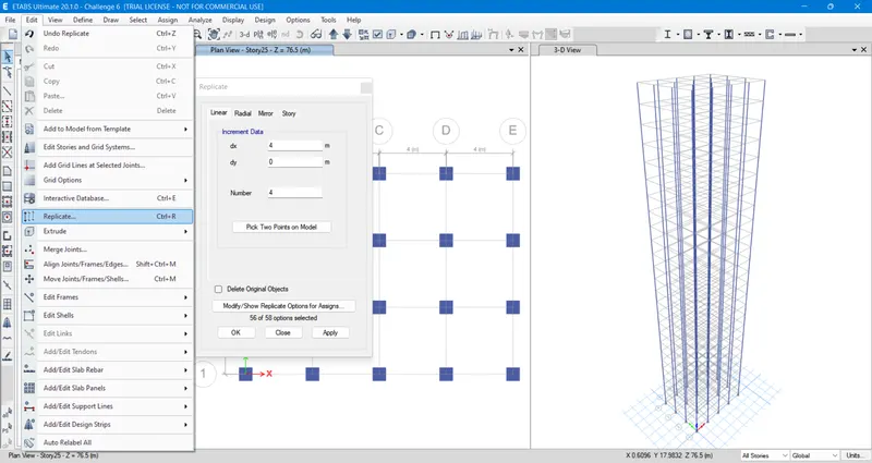
- Followed by select Edit < Replicate < Linear < dx = 4, Numbers = 4 and click OK to replicate the columns to all the intersections of the grid lines.
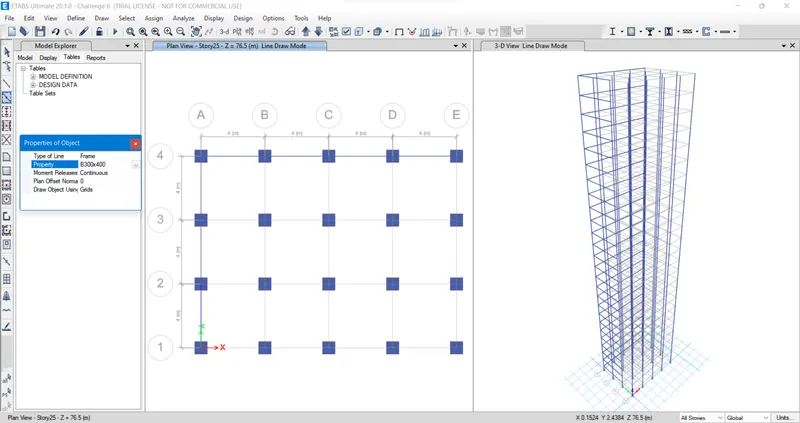
- Likewise the Beams should be assigned to the Created 25 stories building Grid lines by selecting Quick draw Beams/columns Tool (icon) < Properties of object < Property = B300x400.
- And select one side corners and edges of the grids in 2D plan at both X and Y axis like in image below and we can see it will be reflecting in the 3D plan. (Note : Before assigning the Columns, Make sure the " All Stories " option is selected)
- Then Replicate the Remaining Beams inbetween intersection of the grid lines by selecting assigned beams through window selection.
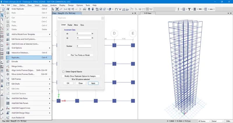
- First select the Beams in the X direction grid lines.
- Followed by select Edit < Replicate < Linear < dy = -4, Numbers = 3 and click OK to replicate the Beams inbetween all intersection of the grid lines.
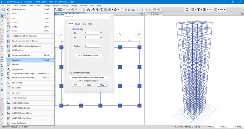
- Likewise Replicate the Remaining Beams inbetween all intersection of the grids lines in the Y direction by selecting assigned beams through window selection.
- Followed by select Edit < Replicate < Linear < dx = 4, Numbers = 4 and click OK to replicate the Beams inbetween all intersection of the grid lines.
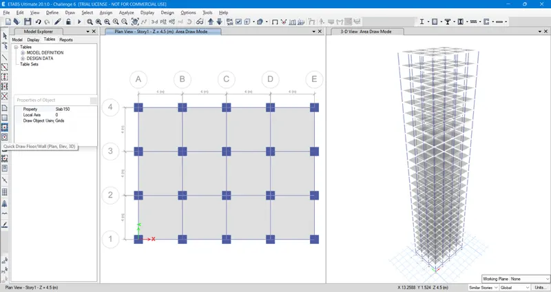
- Then the Slab section has to be assigned in the Floor area of all the 25 stories.
- For that select Quick Draw Floor/Wall Tool (icon) < Properties of Object < Property = Slab150 .
- To create the Slab section at Floor level, click and select the area inbetween the beams and columns.
- Before applying the Slab section select Set Plan view < Storey 1 and change the stories to " Similar stories ".
- To assign the given load over the beams, select all the Beams of 25 stories by clicking Select < Properties < Frame sections < Select by frame Property < B300x400.
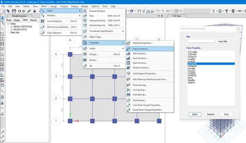
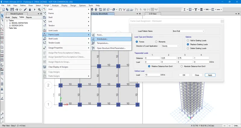
Then click Assign < Frame Loads < Distributed load < Frame load Assignment - Distributed.
From Frame load Assignment - Distributed < Load Pattern Name = Brickwall, Load = 10 KN/m.
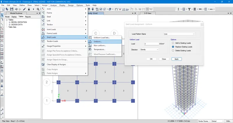
- To assign the given load over Slab Sectiion, select all the slab Section of 25 stories by clicking Select < Properties < slab sections < Select by slab Property < Slab150.
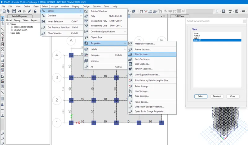
- Then click Assign < Slab Loads < Uniform load < Shell load Assignment - Uniform.
- From Shell load Assignment - Uniform < Load Pattern Name = Live, Uniform load < Load = 3 KN/m.
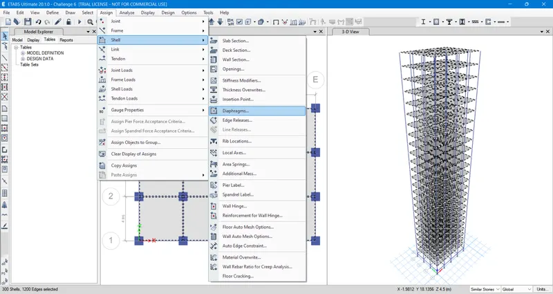
The Slab section should be selected again by clicking Select < Properties < slab sections < Select by slab Property < Slab150.
- Then click Assign < Shell < Diaphragms < Shell Assignment - Diaphragms.
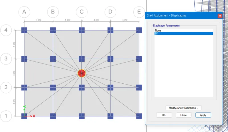
- From Shell Assignment - Diaphragms < D1 and click apply to assign the center of gravity of the Floor.
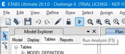
- Atlast we should Run Analysis from the above shown tools over Workspace.
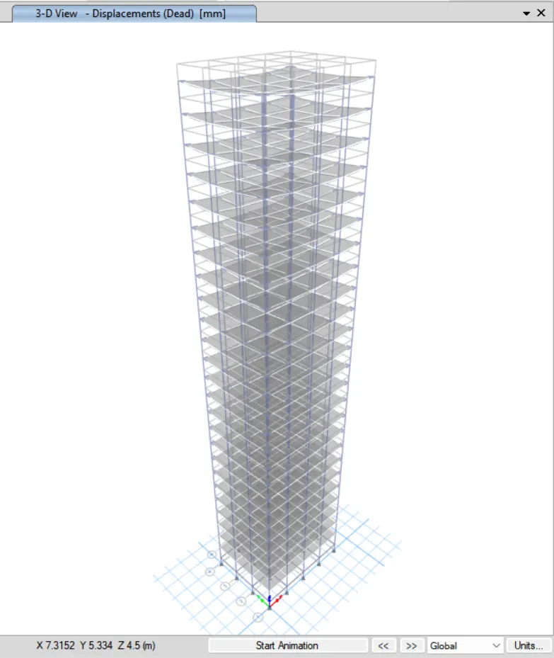
- After the Analysis Run we can see the Structural Deflection of the created 25 stories.
RESULT :
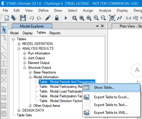
- To see the Analysed result of the created 25 stories modal from Model Explorer Tab < Analysis Results < Structure Output < Modal Information < Tables (Select as appropriate)
- As per the questions asked, the answers will be found in the Below images from the Modal Information.
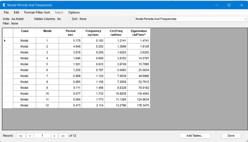
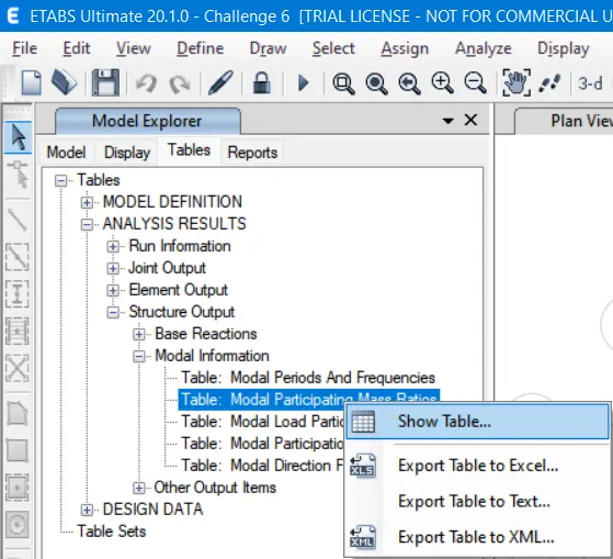
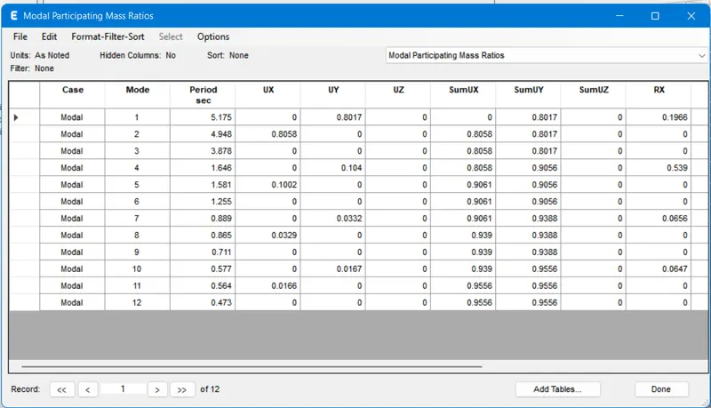
- The Answers for all the Four Questions asked were given in the Table Below.
|
SI.NO |
CRITERIA |
DESIRABLE SOLUTION |
EXERCISE RESULT |
|
|
1. |
Fundamental translational natural period. |
X- Direction |
4.4 second |
4.41 |
|
Y- Direction |
4.2 second |
4.22 |
||
|
2. |
Torsional irregularity |
IS 1893-2016 (Part-1) Table-5. |
Torsional mode Time Period should be lesser than X and Y direction time periods. |
Yes |
|
3. |
Vertical irregularity |
IS 1893-2016 (Part-1) Table-6 Clause-7. |
First three modes together should contribute at least 65% in mass participation factor in each principal direction. |
Yes |
|
Fundamental lateral natural periods in two principal plane directions are away from each other by at least 10%. |
No |
|||
|
4. |
Inter-Storey drift |
IS 1893-2016 (Part-1) Clause-7.11.1.1 |
Storey drift shall not exceed 0.004 times the storey height for base shear with no load factor (4x10⁻³) |
Yes |