Modeling of 3 phase Induction Motor drive with open loop V/f and Direct Torque Control
Aim:
The project aims to design and model a three-phase induction motor for electric vehicle applications. The project consists of three main steps:
Model a three-phase inverter using Simulink and connect it to a three-phase squirrel cage induction motor. Use the V/F method for open-loop control and plot the speed, stator voltage, and frequency of the motor. Use the given design parameters and assumptions for the inverter and the motor:
Design Parameters:
- Power = 100 HP
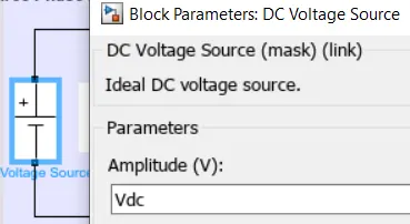
- DC Voltage = 800 V
- Output Voltage = 460 VRMS – line to line
- Initial Speed = 1500 RPM
- Final Speed = 1000 RPM
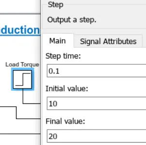
- Initial Load Torque = 10 Nm
- Final Torque=20 Nm
- Torque Step Time = 0.1 secs
Derive the transfer function of the three-phase induction motor using the three-phase induction motor theory. Use the Laplace transform and the equivalent circuit of the motor to obtain the transfer function relating the torque and the speed of the motor.
Model a three-phase induction motor using direct torque control (DTC) with an average model. Implement both torque and flux control to achieve the desired power output. Use the given design parameters and assumptions for the DTC and the motor.
Design Parameters:
- Initial Speed = 0 RPM
- Flux Target = 2.5 webers
- DC Voltage = 500 V;
- Fundamental Frequency = 60 Hz
- Speed Step Time = 0.01 secs
- Determine fundamental speed based upon fundamental frequency
- Determine the switching sequence for direct torque control
- Moment of Inertia = 0.1 Kgm^2
- Load Torque Initial = 0 Nm
- Final Load Torque = 50 Nm
- Torque Step Time = 0.03 secs
Motor Parameters: (Create an Average Model)
- Stator Resistance = 0.5 Ohms
- Rotor Resistance = 0.2 Ohms
- Stator Leakage Inductance = 20 mH
- Rotor Leakage Inductance = 10 mH
- Magnetizing Inductance = 200 mH
- Number of Poles = 4
Theory:
Three phase Inverter:
A three-phase inverter is a device that converts DC power into AC power with three separate phases. Each phase consists of a set of switches that control the flow of current. By modulating the switching of these switches, the inverter can generate a desired AC waveform. The three-phase inverter is widely used due to its ability to efficiently control the speed and torque of three-phase induction motors.
The circuit topology of a 3 phase 2 level inverter is given below in figure 1, includes three legs, each consisting of a pair of switching devices and a DC source.
It consists of six switches, as show below in figure and they are controlled by a pulse width modulation (PWM) technique that determines the output voltage and frequency.
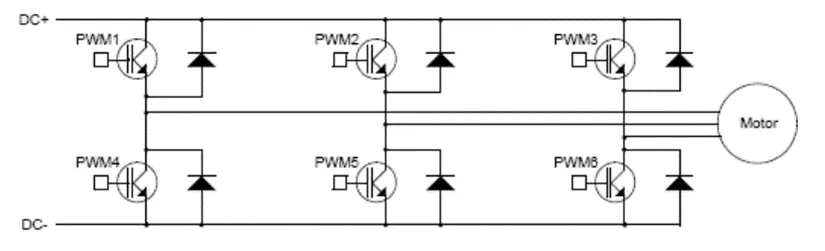
Figure 1 3-phase VSI
The PWM technique varies the pulse width of the switching devices to create a sinusoidal output waveform from a DC input voltage.
The switching sequence of the switches is synchronized so that one switch operates at every 60 degrees of the output waveform to create a line-to-line output waveform with six steps.
The output voltage of each phase is either positive, negative or zero, depending on the state of the switches.
The output voltage of the inverter is proportional to the DC input voltage and the modulation index, which is the ratio of the peak output voltage to the peak DC input voltage.
The output frequency of the inverter is proportional to the switching frequency and the number of pulses per cycle.
SPWM (Sinusoidal Pulse Width Modulation):
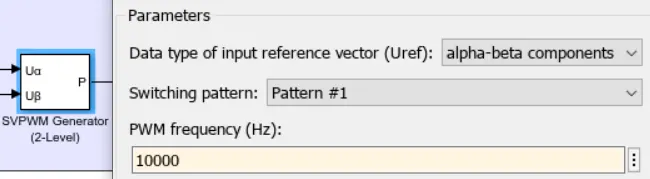
In this project we are using SVPWM switching method to obtain maximum utilization od DC link voltage.
- It is a technique or method to get desired PWM using sine wave as a reference.
- In order to get the suitable pulses, we compare reference signal or modulation signal to carrier signal.
- In SPWM, the carrier signal is triangular signal and modulated signal is sinusoidal signal.
- The carrier frequency is always greater than the modulated signal, and generally we take carrier signal frequency (10-20) times more of modulated signal frequency.
- Magnitude ratio of (Vref/Vcr) is called the modulation index (m), and it defines the magnitude of the output voltage w.r.t DC voltage.
Insight of Three Phase Induction Motor:
A three-phase induction motor is one of the most commonly used motors in industry due to its reliability, efficiency, and cost-effectiveness. It is widely utilized in various applications such as pumps, compressors, conveyors, and many more.
Basic Construction:
The basic construction of a three-phase induction motor consists of two main parts: the stator and the rotor.
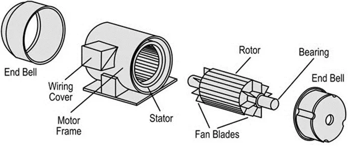
Figure 2- Three phase Induction Motor Construction Diagram
Stator:
The stator is the stationary part of the motor and is made up of a laminated core with evenly spaced windings. These windings are connected to a three-phase power supply, creating a rotating magnetic field.
Rotor:
The rotor, on the other hand, is the rotating part and is made up of laminated iron core with conductive bars known as rotor conductors. These rotor conductors are short-circuited at the ends by end rings. The rotor conductors are placed in the rotating magnetic field generated by the stator, inducing an electromagnetic field in the rotor.
Principle of Operation:
The principle of operation of a three-phase induction motor is based on the interaction between the rotating magnetic field generated by the stator and the induced electromagnetic field in the rotor. When three-phase power is supplied to the stator windings, a rotating magnetic field is created. This rotating magnetic field induces voltages in the rotor conductors, resulting in the flow of current. According to Lenz's law, the direction of the induced current creates a magnetic field that opposes the magnetic field of the stator, causing the rotor to rotate in the same direction as the stator field.
Equivalent Electrical Circuit:
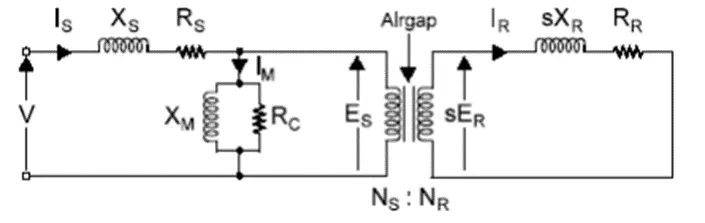
Figure 3-Per phase Equivalent circuit of Three phase Induction Motor
Where V = Stator supply voltage
RS = Stator resistance
ES = Stator induced voltage
XS = Stator leakage reactance
ER = Rotor induced voltage
RR = Rotor resistance
NS = Stator turns
XR = Rotor leakage reactance
NR = Rotor turns
XM = Magnetizing inductance
IS = Stator current
IR = Rotor current
IM = Magnetizing current
RC = Core losses, bearing friction, windage losses
The equivalent electrical circuit of a three-phase induction motor consists of resistances, reactances, and an external mechanical load. The resistances represent the stator and rotor winding resistances, while the reactances represent the leakage reactances of the stator and rotor windings. The external mechanical load is represented as a torque.
In contrast with a DC motor, the AC induction motor does not have separate field windings. As shown in the equivalent circuit, the stator current therefore serves a double purpose:
- It carries the current (IM) which provides the rotating magnetic field
- It carries the current (IR) which is transferred to the rotor to provide shaft torque.
The equivalent circuit can be simplified even further to represent only the most significant components, which are:
- Magnetizing inductance (LM)
- Variable rotor resistance (R’R/s)
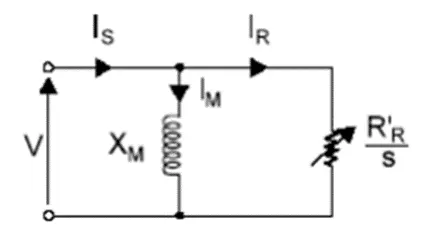
Figure 4- The very simplified equivalent circuit of an AC induction motor
Torque and Speed Curve:
The torque–speed curve can be derived from the equivalent circuit. The output torque of the motor can be expressed in terms of the speed as follows:

This equation and the curve in Figure below, shows how the motor output torque TM varies when the motor runs from standstill to full speed under a constant supply voltage and frequency. The torque requirements of the mechanical load are shown as a dashed line.
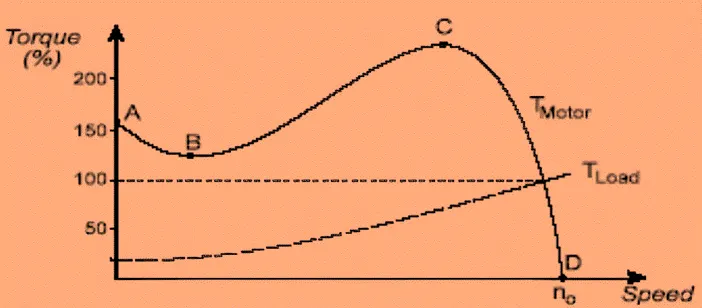
Figure 5 Steady-state torque vs speed characteristic
A: is called the breakaway starting torque
B: is called the pull-up torque
C: is called the pull-out torque (or breakdown torque or maximum torque)
D: is the synchronous speed (zero torque)
Slip (S):
S = (Ns - N) / Ns
Where Ns is the synchronous speed of the motor and N is the actual speed.
The speed-torque curve of a three-phase induction motor shows the relationship between the motor's speed and the torque it can produce. As the load torque increases, the speed decreases, and vice versa. The curve typically exhibits a linear relationship between speed and torque at low values of torque, reaching a maximum torque point, often referred to as the breakdown torque. Beyond this point, the torque decreases with further decrease in speed.
Open loop Volt/Hertz(V/f) Control:
The speed of the rotor depends on the frequency of the applied voltage and the number of poles in the motor. The speed can be expressed as:

where Ns is the synchronous speed in rpm, f is the frequency in Hz, and P is the number of poles.
The torque of the motor depends on the magnitude of the magnetic field, which is proportional to the applied voltage. The torque can be expressed as:
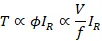
where T is the torque, ϕ is the magnetic flux, V is the voltage, and IR is the rotor current.
To maintain a constant torque, the ratio of V/f must be kept constant. This is achieved by using an inverter that converts a DC voltage to a variable frequency and variable voltage AC output. The inverter can be controlled by different methods, such as Sinusoidal pulse width modulation (SPWM) or Space Vector pulse width modulation (SVPWM).
Torque-speed characteristics for volts/hertz control are as shown in the figure below.
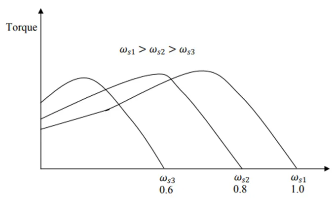
Figure 6 Torque-speed characteristics with volt/hertz control
V/f open loop control is a simple and inexpensive method of controlling the speed and torque of a three-phase induction motor. However, it has some limitations, such as low efficiency at low speeds, poor dynamic response, and reduced torque at high speeds.
Implementation Of V/F Method:
The diagram shows the open-loop V/f control structure implementation.
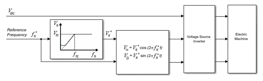
Figure 7 Block diagram of open loop V/f control
Process:
The Controller computes the magnitude of the stator voltage based on the reference frequency, f∗s, as:
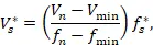
where:
Vn is the rated voltage.
Vmin is the minimum voltage.
fn is the rated electrical frequency.
fmin is the minimum frequency.
The voltage components in the stationary reference frame are:

and

The block obtains Vabc from Vα and Vβ by using an inverse Clarke transformation.
Simulink Model of Three Phase Induction Motor with open loop V/f control:
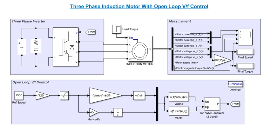
Inserted figures:
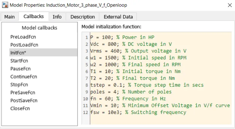
With the help of Model Properties, we initiate the all the required given design parameters as follows,
Blocks used:
Universal Bridge:
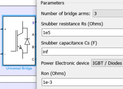
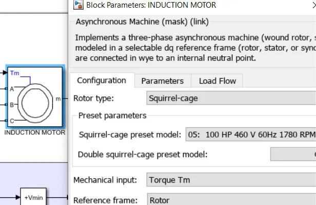
Asynchronous Machine Block:
DC Voltage Source:
SVPWM Generator (2-level) Block:
Step block:
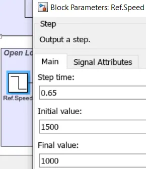
Step bocks are used to introduce step change at desired step time. We used to define load tarque and reference speed of the motor as follows,
Bias Block:
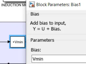
It is used to add some offset in characteristic, as we know it, in V/f plot initial value of V is not zero because of the voltage drop in stator resistance, so we assume the offset voltage of 10V.
Result:
We simulate the model for 2 sec and following plots are obtained,
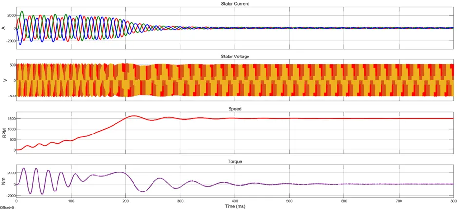
Case-01: When reference speed is 1500rpm.
Zoom-Out:
Zoom-In:
As we can see that in speed plot, during transient motor tries to catch the equilibrium point or a stable point. It shows some oscillations which are not healthier for three phase induction motor.
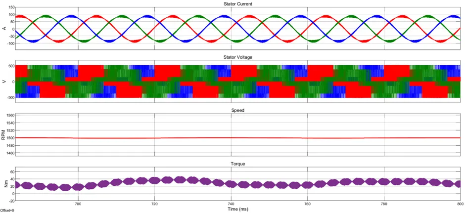
During steady state motor speed reaches to their reference speed that is 1500rpm. It shows that the open loop V/f control is working fine.
In the stator voltage plot, during transient peak voltage per phase is around 515.5V and in steady state this voltage equivalent to the rating of the motor that we choose in the motor preset, that is 460V.
In the stator current, during transient the oscillations are huge but in steady state stator current behaviour is normal the per phase rms current is measured to 61.23A.
At 100ms the load torque is changes from 10Nm to 20Nm, but due V/f control speed of the motor is consistent to reference speed that is 1500rpm. And, the motor electrical torque is not changing enough, steady state motor torque is around 25.31Nm.
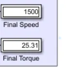
Figure 8 Steady-state speed and torque
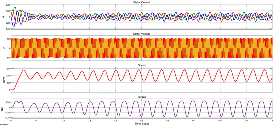
Case-02: When reference speed is 1000rpm.
Zoom-Out:
Zoom-In:
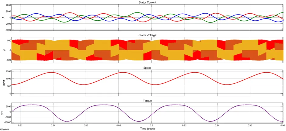
After 0.4sec, motor avg. speed is 1000rpm, it is also oscillatory in nature. In motor torque we observe huge oscillations.
In stator voltage and currents have more ripple when the speed set point is set to 1000rpm, but set point is set to 1500rpm oscillations and ripples are very less.
Derive the transfer function of the three-phase induction motor using the three-phase induction motor theory. Use the Laplace transform and the equivalent circuit of the motor to obtain the transfer function relating the torque and the speed of the motor.
To derive the transfer function of a three-phase induction motor, we need to use the concept of space vector theory and the d-q reference frame. The space vector theory represents the three-phase voltages and currents as complex vectors that rotate in a two-dimensional plane. The d-q reference frame is a coordinate system that rotates with the stator's magnetic field, such that the d-axis is aligned with the direct axis of the field and the q-axis is aligned with the quadrature axis of the field. By transforming the stator and rotor variables from the stationary abc frame to the rotating d-q frame, we can simplify the analysis of the motor and obtain a linear model.
The transformation matrix from the abc frame to the d-q frame is given by:
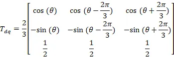
where  is the angle of the d-axis with respect to the a-axis.
Using this transformation, we can write the stator and rotor voltages in the d-q frame as:
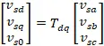
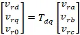
Similarly, we can write the stator and rotor currents and flux linkages in the d-q frame as:
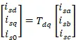
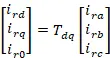
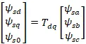
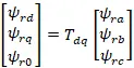
The voltage equations for the stator and rotor in the d-q frame are given by:
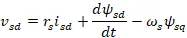
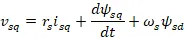

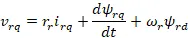
where  and
and  are the stator and rotor resistances,
  and
and  are the stator and rotor angular velocities, and
  ,
,  ,
,  , and
, and  are the stator and rotor flux linkages in the d-q frame.
The flux linkages are related to the currents by the following equations:




where  and
and  are the stator and rotor self-inductances, and
  is the mutual inductance between the stator and rotor.
The torque equation for the motor is given by:
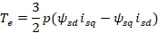
where  is the electromagnetic torque and
  is the number of pole pairs.
The mechanical equation for the motor is given by:
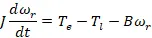
where  is the moment of inertia of the rotor,
  is the load torque, and
  is the viscous friction coefficient.
To obtain the transfer function of the motor, we need to eliminate the flux linkages and the currents from the equations and express the output variable (rotor speed or torque) as a function of the input variable (stator voltage). This can be done by using the Laplace transform and solving the system of equations algebraically.
The transfer function of the motor from the stator voltage to the rotor speed is given by:

where  and
and  are constants that depend on the motor parameters, and
  and
and  are the equivalent inductance and resistance of the stator and rotor circuits.
The transfer function of the motor from the stator voltage to the torque is given by:
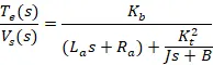
where  is another constant that depends on the motor parameters.
These transfer functions can be used to analyse the dynamic behaviour of the motor and design controllers for speed or torque regulation.
Model a three-phase induction motor using direct torque control (DTC) with an average model. Implement both torque and flux control to achieve the desired power output. Use the given design parameters and assumptions for the DTC and the motor.
Direct Torque Control (DTC):
The first major successful commercial DTC products, developed by ABB, involved traction applications late in the 1980s.
Direct Torque Control (DTC) is a control technique used in AC motor drives to control the torque and flux of an induction motor directly without the need for a traditional motor controller such as a field-oriented control (FOC) system.
Operational Principle
DTC operates by directly controlling the stator flux and electromagnetic torque by selecting the appropriate inverter voltage vector based on the error between the actual and reference values of flux and torque. The control algorithm divides the voltage space into sectors and selects the most suitable voltage vector within a specific sector to minimize the torque and flux errors.
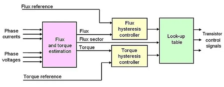
Figure 9 Block diagram of DTC
DTC is a way of controlling the speed and power of an electric motor by changing the magnetic fields inside it. The magnetic fields are created by the voltage and current that flow through the motor's wires. The voltage and current can be changed by switching on and off some transistors in a device called a variable frequency drive.
The magnetic fields have two parts: one that comes from the stator (the stationary part of the motor) and one that comes from the rotor (the rotating part of the motor). The stator field can be changed quickly by changing the voltage, while the rotor field changes slowly because of the inertia of the rotor. The angle between the stator and rotor fields affects the torque (the force that makes the rotor spin).
To control the torque, we need to change the angle between the stator and rotor fields. We can do this by choosing the right voltage for the stator. The voltage has a direction and a size, which we call a vector. The stator field follows the direction and size of the voltage vector. If we change the voltage vector, we change the stator field, and thus the angle with the rotor field.
The torque can be calculated by a formula that involves the stator and rotor fields and the angle between them. The formula looks like this:

where is the torque,  is the number of poles,
  is the mutual inductance,
  and
and  are the stator and rotor inductances, is the leakage factor,
  and
and  are the stator and rotor fluxes, and
  is the angle between them.
To estimate the stator and rotor fluxes, we need to measure the voltage and current of the motor. The stator flux can be estimated by adding up the voltage over time, while the rotor flux can be estimated by multiplying the current by a constant. These are called integration methods.
We can simplify the integration methods by ignoring some small effects, such as the resistance of the wires and the variation of the DC voltage. This makes the calculations easier and faster. The simplified methods look like this:
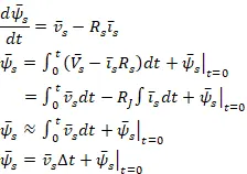
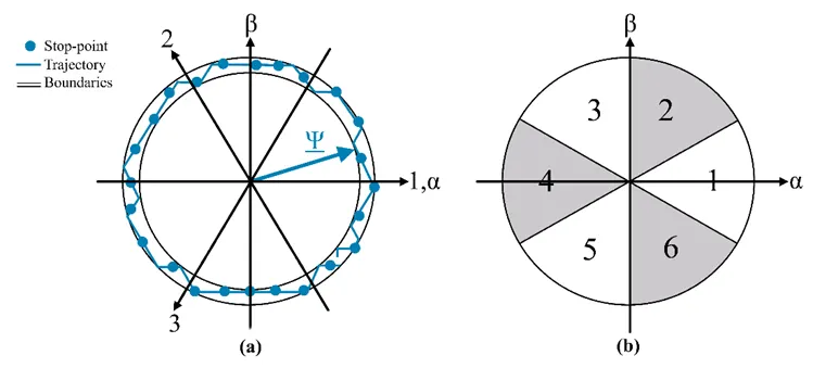
Figure 10 Stator flux vector trajectory(a) Sector selection(b)
here is the stator flux,  is the stator voltage, and
  is the time interval.
Flux comparator or Flux Hysteresis Controller (2-level):
Flux hysteresis controller (2-level) is a part of direct torque control (DTC) technique for three-phase induction motor drives. It compares the actual and reference values of stator flux magnitude and generates a control signal to correct the error. The control signal is used to select the optimal voltage vector for the motor inverter through a switching table. The flux hysteresis controller helps to achieve fast and accurate torque and flux regulation.
The logic of the flux hysteresis controller can be explained as follows:
- The reference stator flux magnitude
 is kept constant at a desired value.
 - The actual stator flux magnitude
 is estimated from the stator voltage and current measurements using the following formula:
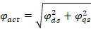
where  and
and  are the stator flux components in the dq coordinate system.
- The flux error
 is calculated by subtracting the actual flux from the reference flux:

- The flux error is compared with a hysteresis band
 , which defines the upper and lower limits of the acceptable flux deviation. If the flux error exceeds the hysteresis band, a control signal
  is activated to increase or decrease the stator flux. The control signal can have two possible values: +1, 0 depending on the sign and magnitude of the flux error.
Torque Hysteresis Controller(3-level):
The torque hysteresis controller (3-level) in direct torque control (DTC) of three phase induction motor is a technique that allows to control the motor torque and flux by selecting the optimal voltage vector from a three-level inverter. The three-level inverter has more voltage levels than the conventional two-level inverter, which improves the quality of the output voltage and reduces the harmonic distortion. The logic of the torque hysteresis controller is as follows:
- The torque is estimated from the stator voltages and currents.
- The estimated torque is compared with the reference values and the errors are fed to 3-level hysteresis comparator.
- The hysteresis comparators generate control signals for the torque based on the sign and magnitude of the errors.
- The control signal can have three possible values: +1, 0, and -1 depending on the sign and magnitude of the torque error.
Block diagram of DTC Control:
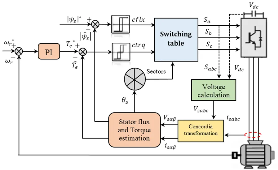
Figure 11Full block diagram of DTC control with Hysteresis controller
Estimation of Switching Table:
Switching sequence for direct torque control is determined by the optimal switching table, which depends on the stator flux linkage position and the control signals generated by the hysteresis comparators. The table below shows an example of the optimal switching table for a three-phase induction motor with six sectors.
Table 1 Space vector selection table
|
Change in Flux |
Change in Torque |
S1 |
S2 |
S3 |
S4 |
S5 |
S6 |
|
Increase (1) |
Increase (1) |
011 |
010 |
110 |
100 |
101 |
001 |
|
Slow Decrease (0) |
111 |
000 |
111 |
000 |
111 |
000 |
|
|
Decrease (-1) |
101 |
001 |
011 |
010 |
110 |
100 |
|
|
Decrease (-1) |
Increase (1) |
010 |
110 |
100 |
101 |
001 |
011 |
|
Slow Decrease (0) |
000 |
111 |
000 |
111 |
000 |
111 |
|
|
Decrease (-1) |
100 |
101 |
001 |
011 |
010 |
110 |
Simulink Model of Three Phase Induction Motor with Direct Torque Control:
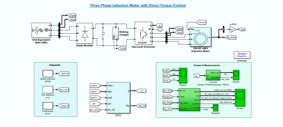
DTC Subsystem:
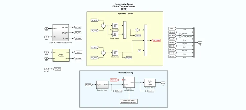
Determination of suitable space vector:
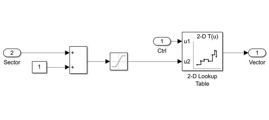
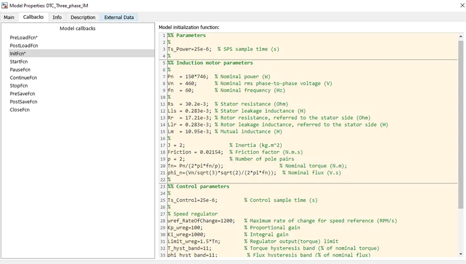
Parameters:
Result:
We simulate the model for 4sec and following plots are obtained.
Motor Torque, Speed and flux Plot:
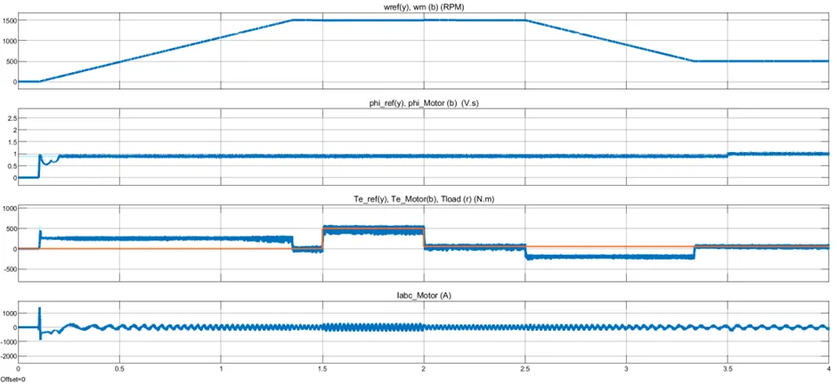
Initially, the flux reference is set to 0.9 V.s.
- At 0.1s, the speed reference is set to 1500 RPM and the motor starts to accelerate. You can see that the motor speed precisely follows the speed reference whose maximum rate of change is limited to 1200 rpm/s. The 1500 RPM set point is reached at 1.35s.
- At 1.5s, a load torque of 500 N.m is applied to the motor. The DTC control operates to maintain the motor speed at 1500 RPM.
- At 2s, the load torque is reduced to 50 N.m and at 2.5s, the speed reference is reduced to 500 RPM. Observe on Scope 1 the braking chopper operation to dissipate the kinetic energy produced by the motor in order to avoid overvoltage on the DC bus.
- At 3.5s, the flux reference is increased from 0.9 to 1.0 V.s.
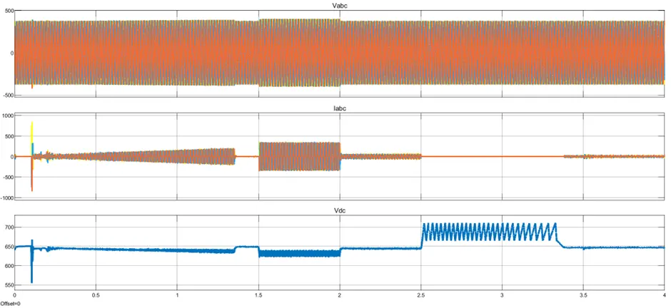
Stator Current and Voltage Plot:
Zoom-Out:
Zoom-In:
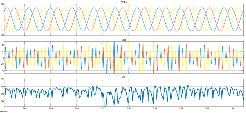
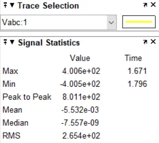
Statics of Stator per phase voltage:
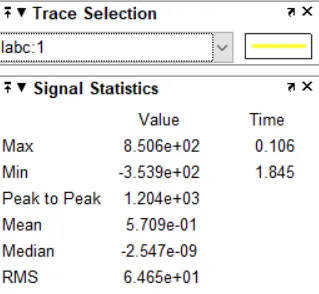
Statics of Stator per phase current:
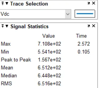
Statics of DC link voltage:
Conclusion:
In this project I learn, various methods to control VSI fed three phase Induction Motor like, V/f open loop and DTC and design Simulink model for each and also gain the knowledge of Space vector, modelling of induction machine etc.
Reference:
- Bose, B. K. Modern Power Electronics and AC Drives. Upper Saddle River, NJ: Prentice-Hall, 2002.
- Grelet, G. and G. Clerc. Actionneurs électriques. Paris: Éditions Eyrolles, 1997.
- Krause, P. C. Analysis of Electric Machinery. New York: McGraw-Hill, 1986.
- M. Cirrincione, M. Pucci, G. Vitale, Power Converters and AC Electrical Drives with Linear Neural Networks, CRC Press, 2012
- Technical guide No. 1
Direct torque control – the world’s most advanced AC drive technology, ABB 2011
- Buja, G. S., and M. P Kazmierkowski. "Direct Torque Control of PWM Inverter-Fed AC Motors—A Survey." IEEE Transactions on Industrial Electronics 51, no. 4, (2004): 744 - 757.
- Zhang, Z., Liu, Y., & Bazzi, A. M. (2017, March). An improved high-performance open-loop V/f control method for induction machines. In 2017 IEEE Applied Power Electronics Conference and Exposition (APEC) (pp. 615-619). IEEE.
- Boldea, I., Moldovan, A., & Tutelea, L. (2015, September). Scalar V/f and If control of AC motor drives: An overview. In 2015 Intl Aegean Conference on Electrical Machines & Power Electronics (ACEMP), 2015 Intl Conference on Optimization of Electrical & Electronic Equipment (OPTIM) & 2015 Intl Symposium on Advanced Electromechanical Motion Systems (ELECTROMOTION) (pp. 8-17). IEEE.
- Ratnani, P. L., & Thosar, A. G. (2014). Mathematical modelling of an 3 phase induction motor using MATLAB/Simulink. International Journal Of Modern Engineering Research (IJMER), 4(6), 62-67.
- De Aguiar, M. L., & Cad, M. M. (2000, January). The concept of complex transfer functions applied to the modeling of induction motors. In 2000 IEEE Power Engineering Society Winter Meeting. Conference Proceedings (Cat. No. 00CH37077) (Vol. 1, pp. 387-391). IEEE.
Simulation File:
https://drive.google.com/file/d/1iaaFZ4LIjcqpmYCcFw2P-Q4iiPRQ8fnt/view?usp=sharing