Implement control logic of a “washing machine” using MATLAB State flow and the “Gear shift” logic
Q.1 Implement control logic of a “washing machine” using Stateflow as per the given sequence:
- If the power supply is available, the system gets activated
- If the Water supply is not available, stop the process & indicate through the LED
- The soaking time should be 200s followed by a Washing time of 100s.
- Then rinsing happens for the next 20s & dryer runs for 50s
After all the processes have been completed turn on the finished LED
Solution:
Washing Machine:
A washing machine is an appliance that is used for washing clothes, linens, and other items. It is a machine that uses water and detergent to remove dirt and stains from clothes, making the cleaning process faster and easier than hand washing.
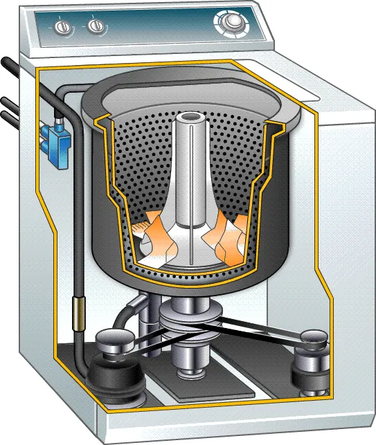
Washing machines typically use mechanical action, such as agitators or drum rotation, to move the clothes around in the water and help remove dirt and stains. They also use water, detergent, and sometimes heat to improve cleaning performance. The machine controls the water level, temperature, and cycle time, and it is operated through a control panel or display.
Stages of washing machine:
- Soaking:
The soaking state in a washing machine is a stage in the washing cycle where the clothes are allowed to soak in the water and detergent mixture for a certain amount of time. This stage is designed to allow the detergent to penetrate and loosen the dirt and stains on the clothes, making it easier to remove them during the washing and rinsing cycles.
- Washing:
The washing state in a washing machine is the stage in the washing cycle where the clothes are agitated or rotated in the water and detergent mixture to remove dirt and stains. The mechanical action of the drum or agitator helps to loosen and suspend the dirt and stains in the water, while the detergent works to dissolve and remove them from the fabric.
- Rinsing:
The rinsing state in a washing machine is the stage in the washing cycle where the clothes are rinsed with clean water to remove any remaining detergent, dirt, and other debris from the fabric. This stage is important for removing any residue that may cause skin irritation or damage to the fabric, as well as improving the overall cleanliness of the clothes.
During the rinsing state, the machine drains the water and detergent mixture from the drum and refills it with clean water. The drum rotates or the agitator moves the clothes around in the water to help rinse away any remaining debris. The rinsing process is typically repeated several times to ensure thorough cleaning.
- Drying:
The drying stage in a washing machine is the final stage in the washing cycle where the clothes are dried after being washed and rinsed. There are two main types of drying in washing machines: air-drying and tumble-drying.
- Air-drying:
Air-drying is a simple, energy-efficient method where the clothes are left to air-dry on a clothesline or drying rack. This method can take several hours to a full day, depending on the humidity and temperature.
- Tumble-drying:
Tumble-drying, on the other hand, is a more efficient and faster drying method where the clothes are placed in the washing machine drum and the machine circulates hot air to remove the moisture. Tumble-drying can be done in a conventional washing machine or in a separate dryer.
Washing process through Animation:
Blocks used:
- Chart Block:
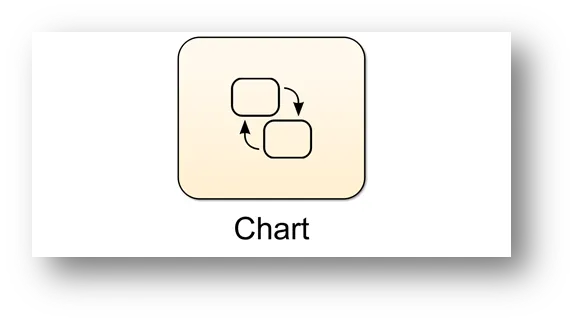
A chart block in Simulink is a graphical representation of a finite state machine (FSM) or a hybrid system, which is a combination of discrete and continuous behavior. The chart block allows you to define states and transitions between them, specify the behavior of each state, and specify the conditions under which transitions occur.
- Lamp Block:
Lamp blocks are elements commonly used in simulation software, such as Simulink, to represent the status or state of a signal. In Simulink, these blocks can be used to display a signal as either on or off, represented as a green or red light, respectively. The color of the light changes based on the value of the input signal, allowing you to easily see the state of the system being modeled.
Lamp blocks are often used in conjunction with other blocks, such as switches and comparators, to build and analyze complex dynamic systems.
- Rocker Switch:
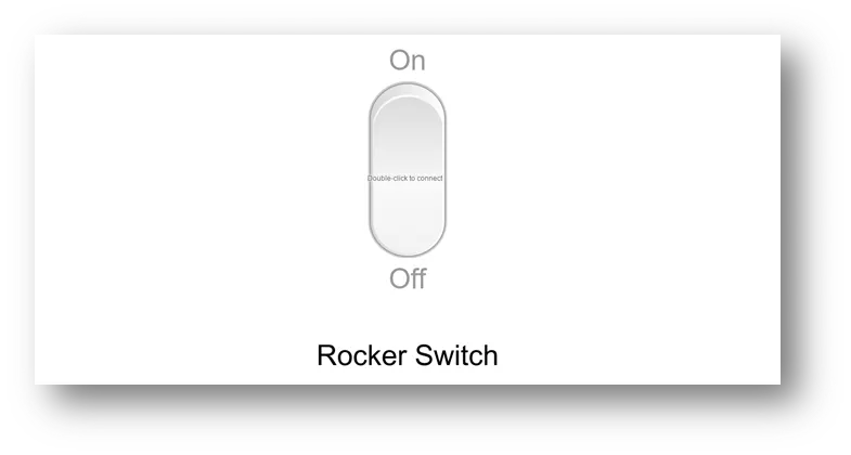
A rocker switch block in Simulink is a type of switch that can be used to represent a real-world switch in a Simulink model. A rocker switch can be set to either an "on" or "off" position, and the state of the switch is used to control the flow of signals in a model.
Control Logic of a Washing Machine:
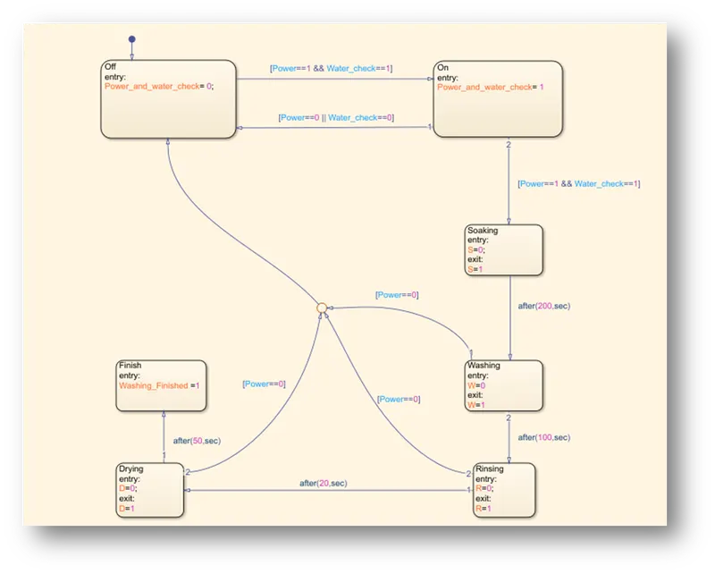
Symbols Pane:
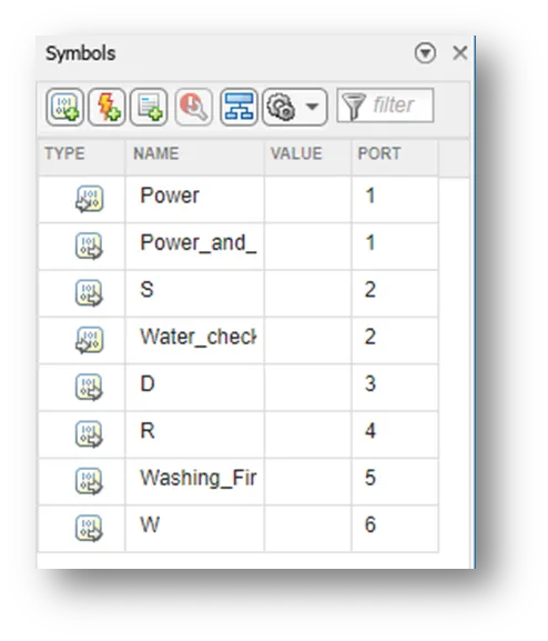
Simulink Model of Washing Machine:
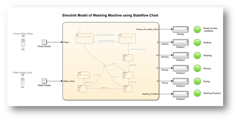
Now we go step-by-step process in order to perform one time Wash:
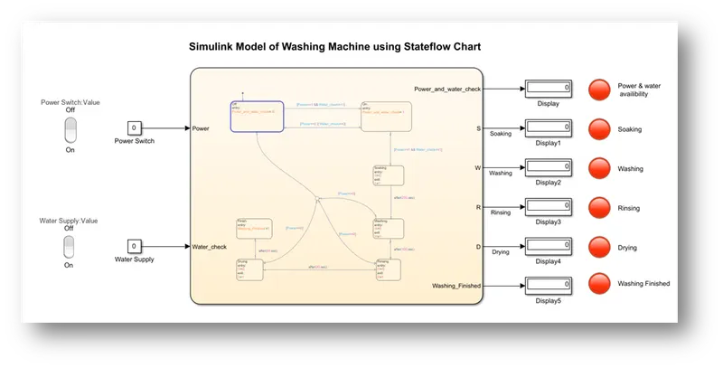
- Power-Off condition when washing machine is not operational:
- Power-ON and Water supply ON condition: LED turn from Red to Green color:
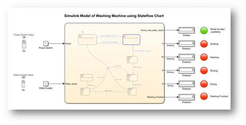
- Soaking State:
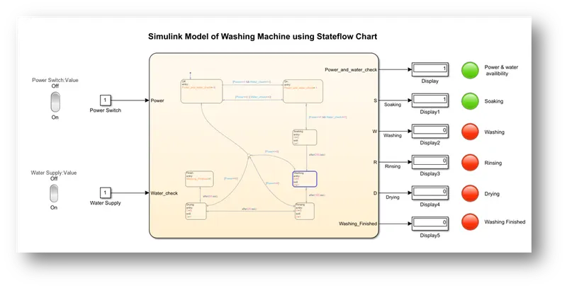
- Washing ON State:
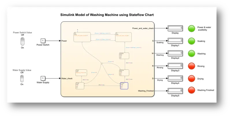
- Rinsing State:
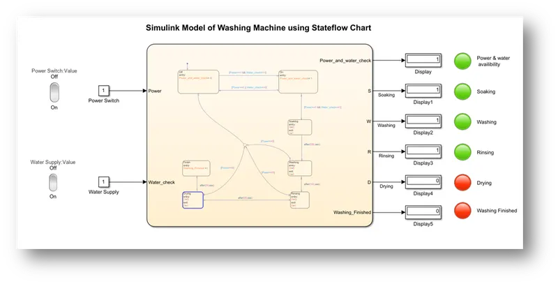
- Drying State:
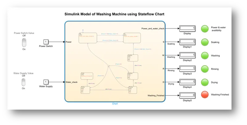
- Finally Washing Finished State:
Conclusion:
We simulate this model for 400sec, and observe that when Power and Water supply is ON condition, all the states of washing machine execute smoothly. At any point of time if power is cut during washing or any other state of washing machine the machine is going back to “OFF” state.
Q.2 Make a Simulink chart for the “Gear shift” logic as per below conditions:
Speed Range(kmph) Gear
0 to 15 1
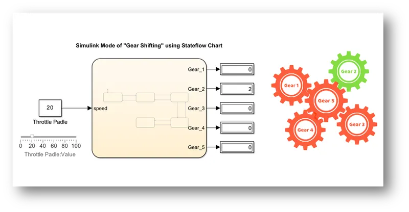
16 to 25 2
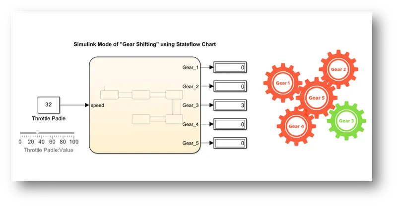
26 to 40 3
41 to 60 4
Above 61 5
Give speed input while the simulation is running & display the gear number.
Solution:
Aim:
Make a Simulink chart for the “Gear shift” logic as per conditions given in the problem.
Theory:
Gear shift refers to the mechanism used in a motor vehicle to change gears. It is the lever or control that is used to engage and disengage different gears in the transmission system of an automobile. This allows the driver to adjust the engine speed to the road speed, providing the appropriate amount of power and torque for driving conditions.
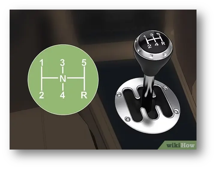
The gear shift can be found in both manual and automatic transmission vehicles, and the number of gears can vary depending on the make and model of the vehicle. In a manual transmission vehicle, the driver uses the gear shift to physically shift gears, while in an automatic transmission vehicle, the gear shift typically operates as a selector for different driving modes such as park, reverse, neutral, drive, and others.
Automatic Gear Transmission Mechanism:
In an automatic transmission vehicle, the gear shift mechanism operates as a selector for different driving modes, such as park, reverse, neutral, drive, and others. The gear shift mechanism typically consists of a lever or button, which is connected to the transmission control unit (TCU) by a series of mechanical linkages or electrical signals.
When the driver selects a driving mode, such as drive or reverse, the TCU sends a signal to the transmission to change gears. The TCU uses various inputs, such as engine speed, road speed, and accelerator pedal position, to determine the appropriate gear ratio for the driving conditions. The transmission then shifts gears as necessary to maintain the desired gear ratio.
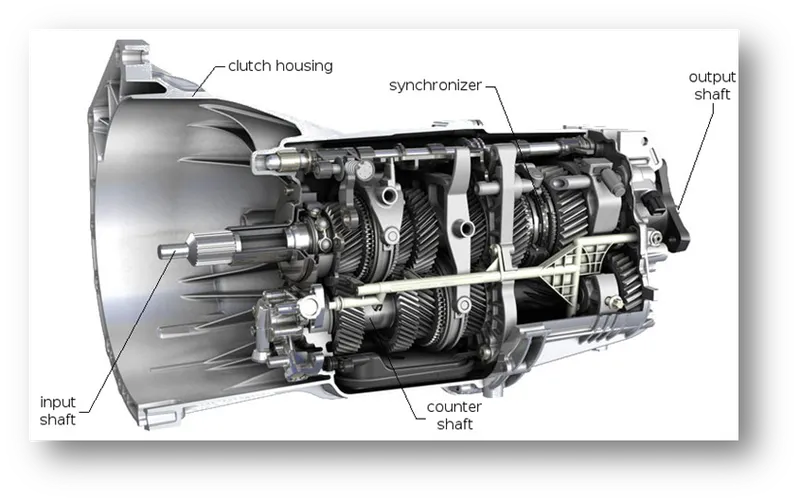
In some vehicles, the gear shift mechanism is integrated into the center console, while in others it is located on the steering column or on the dashboard. Some newer vehicles may even have a push-button gear shift mechanism, rather than a traditional lever or button. Regardless of the design, the gear shift mechanism in an automatic transmission vehicle allows the driver to select the driving mode, while the transmission and TCU handle the gear shifting.
These are the following block set required to simulate the model of “Gear Shifting”:
- Chart Block
- Slider Block
- Constant Block
- Display Block
- Lamp Block
Control Logic of “Gear Shifting”:
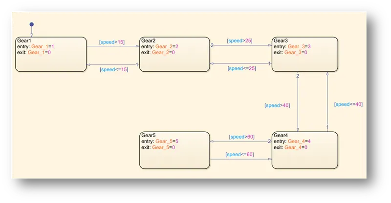
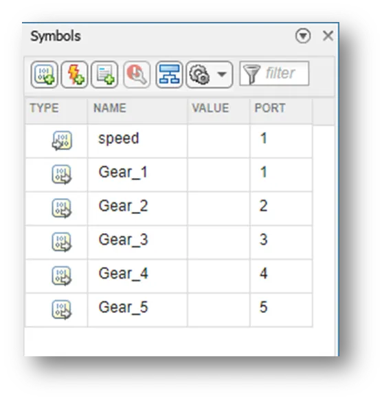
Symbols Pane:
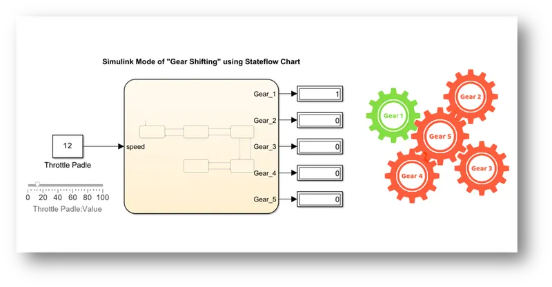
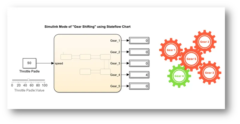
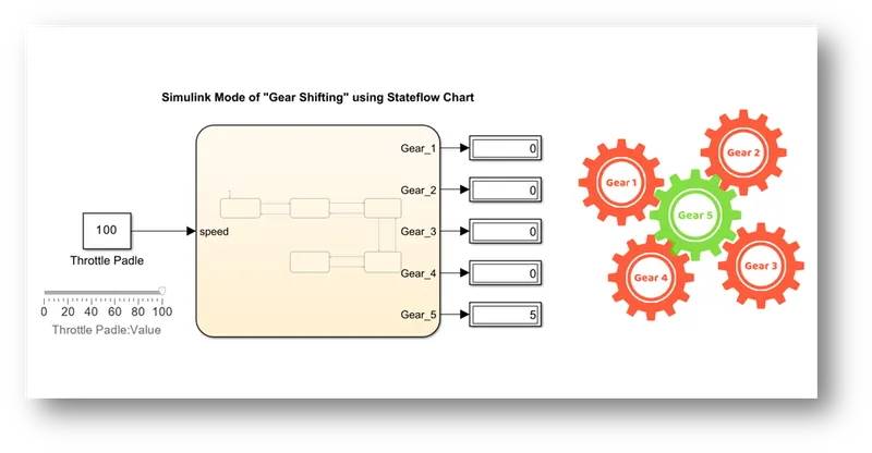
Simulink Model of Gear Shifting at variable Speed:
- When speed is 0-15kmph: “Gear 1” turns to Green.
- When speed is 16-25kmph: “Gear 2” turns to Green.
- When speed is 26-40kmph: “Gear 3” turns to Green.
- When speed is 41-60kmph: “Gear 4” turns to Green.
- When speed is above 60kmph: “Gear 5” turns to Green.
Result:
Hence, we see that for variable speed, Gear shifting is done according to their transition condition.
Asset link: