MBD Simulation on IC Engine Valve Train
Aim:
To perform MBD Simulation on IC Engine Valve Train.
Objective:
-
Model the parts and assemble them in SolidWorks.
-
Run the simulation using the below parameters
|
Sl. No |
CAM Lift (mm) |
Speed (RPM) |
Material |
|
1 |
3.5 |
1500 |
Cast Carbon Steel |
|
2 |
6 |
1500 |
Cast Carbon Steel |
Obtain the Plot of the following:
-
Valve Lift.
-
The contact force between
-
Cam and PushRod
-
Pushrod and Rocker Arm
-
Rocker Arm and Valve
Explain why the contact force between tkhe Rocker arm and valve varies while measuring with respect to the X direction and measuring with respect to magnitude.
Basic Definitions:
The valve train in an internal combustion (IC) engine is a crucial component responsible for controlling the opening and closing of the engine's intake and exhaust valves. It plays a key role in the overall performance and efficiency of the engine. The basic idea behind the valve train is to ensure precise timing and coordination of the valve movements with the engine's piston movements.
Here are the fundamental components and concepts associated with the valve train in an IC engine:
1.Valve Train
A valve train is a mechanical system that controls the operation of the intake and exhaust valves in an internal combustion engine.
The intake valves control the flow of air/fuel mixture (or air alone for direct-injected engines) into the combustion chamber, while the exhaust valves control the flow of spent exhaust gasses out of the combustion chamber once combustion is completed. Internal combustion engines typically have two types of valves – intake valves and exhaust valves. The intake valves allow the fresh air-fuel mixture to enter the combustion chamber, while the exhaust valves allow the combustion gasses to exit.
2.Camshaft
The camshaft is a rotating shaft with specially shaped lobes that act as cams. These lobes are designed to lift and lower the valves at specific intervals during the engine's four-stroke cycle (intake, compression, power, and exhaust). The camshaft is usually driven by the engine's crankshaft through a timing belt or chain.A camshaft is a rotating object— usually made of metal— that contains pointed cams, which converts rotational motion to reciprocal motion.
The timing and lift profile of the valve opening events are controlled by the camshaft, through use of a carefully shaped lobe on a rotating shaft. The camshaft is driven by the crankshaft and— in the case of a four-stroke engine— rotates at half the speed of the crankshaft. Motion is transferred from the crankshaft to the camshaft most commonly by a rubber timing belt, a metallic timing chain or a set of gears.
3.Cam Lobe
The cam lobes on the camshaft are responsible for pushing against the valve lifters, which in turn open the valves. The shape and size of the cam lobes determine the valve lift and duration – factors that influence the engine's performance
The cam lobe is the basis of valve opening and closing rates, amount of lift, and operating RPM ranges. The lobe profile can directly act on the valve, as in some over-head camshaft applications, or be amplified by rocker arms.
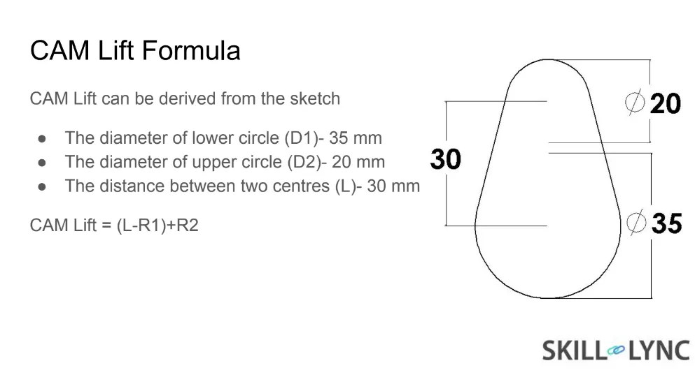
Radius of Lower/Base Circle = R1
Radius of Upper Circle = R2
Distance between the two centres = L
Cam Lift formula = (L-R1) + R2
4. Valve Lifters
Valve lifters, also known as tappets, are components that transmit the motion from the camshaft to the valves. They follow the contours of the cam lobes and transfer the upward and downward movements to the valves.
5.Pushrod
Pushrods are long, slender metal rods that are used in overhead valve engines to transfer motion from the camshaft (located in the engine block) to the valves (located in the cylinder head). The bottom end of a pushrod is fitted with a lifter, upon which the camshaft makes contact. The camshaft lobe moves the lifter upwards, which moves the pushrod. The top end of the lifter pushes on the rocker arm, which opens the valve.In some engine designs, especially older ones or those with specific configurations, pushrods are used to transmit the motion from the lifters to the rocker arms.
6. Rocker arm
A rocker arm is an oscillating lever that conveys radial movement from the cam lobe into linear movement at the poppet valve to open it. One end is raised and lowered by a rotating lobe of the camshaft (either directly or via a tappet (lifter) and pushrod) while the other end acts on the valve stem.Rocker arms are pivoting components that convert the linear motion from the pushrods or directly from the lifters into a rotational motion to open and close the valves.
7.Valve Spring
Valve springs take on the task of controlling the valvetrain. Spring pressure is the major factor that forces its components to stay in contact with the camshaft lobe. Other forces play a role, but without the proper spring pressure the valvetrain becomes uncontrollable.“The goal is to ‘control’ the valve and prevent ‘valve float,’ which robs the engine of power and can ultimately cause failures.”
Valve spring pressure must be enough to shut the valve and keep it from bouncing off of the valve seat. When valve bounce occurs, dynamic compression is lowered resulting in a loss of power. Bouncing the valve off the seat also can cause valve breakage or piston to valve contact. The result is catastrophic engine failure.
Valve float will occur when the valvetrain gear loses contact with the camshaft lobe. Lifters, pushrods, rocker arms, and valves may lose contact if the open pressure of the spring is not sufficient. Open pressures are critical because the spring force is opposing the inertia of the valvetrain. If inertia of the opening valve overcomes spring force, the spring has lost the ability to keep the valvetrain following the cam lobe profile.
Weak springs will allow the lifter/push rod to loft over the nose of the camshaft. What goes up must come down. The landing causes damage to the bearings and axle. This will eventually pound the axle out of the lifter body and cause catastrophic failure.”Valve springs are used to close the valves after they have been opened by the camshaft. They ensure that the valves seat properly and prevent any unwanted bouncing or floating of the valves.
8.Timing Belt/Chain
The timing belt or chain connects the crankshaft and the camshaft, ensuring that the valve events are synchronized with the piston movements. Proper timing is crucial for efficient combustion and engine performance.
The valve train, by controlling the opening and closing of valves, determines the amount of air-fuel mixture entering the combustion chamber and the timely expulsion of exhaust gases. Precise valve timing is essential for optimizing engine performance, fuel efficiency, and emissions. Modern engines often use overhead camshaft designs, where the camshaft is located above the cylinder head, for better control and efficiency.
The opening and closing rates and lift at the valve depends on:
-
The Cam Lobe
-
Rocker arm ratios
Higher rocker arm ratios will amplify the opening and closing rates and lift at the valve.
-
Valve Spring
Calculations:
In order to get desired Cam lift, the center distance between the upper and lower circle (L) in a cam can be varied.
-
Case 1: To obtain cam lift of 3.5mm.
R1 = 12.50mm
R2 = 5mm
Cam Lift = (L-R1) + R2
3.5 = (L-12.5) + 5
L = 11mm
-
Case 2: To obtain cam lift of 6mm.
R1 = 12.50mm
R2 = 5mm
Cam Lift = (L-R1) + R2
6 = (L-12.5) + 5
L = 13.50mm
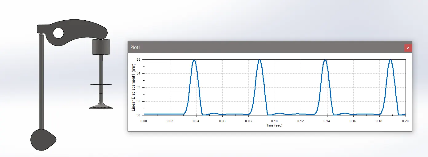
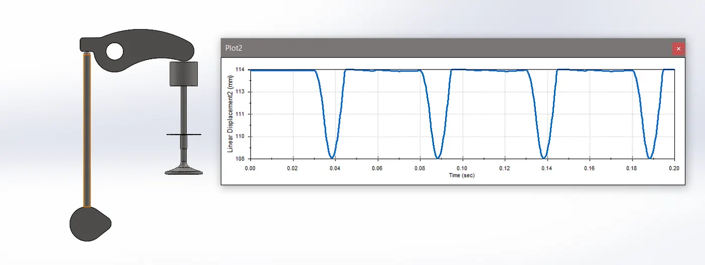
Case 1:
Displacement of Push Rod and Valve:
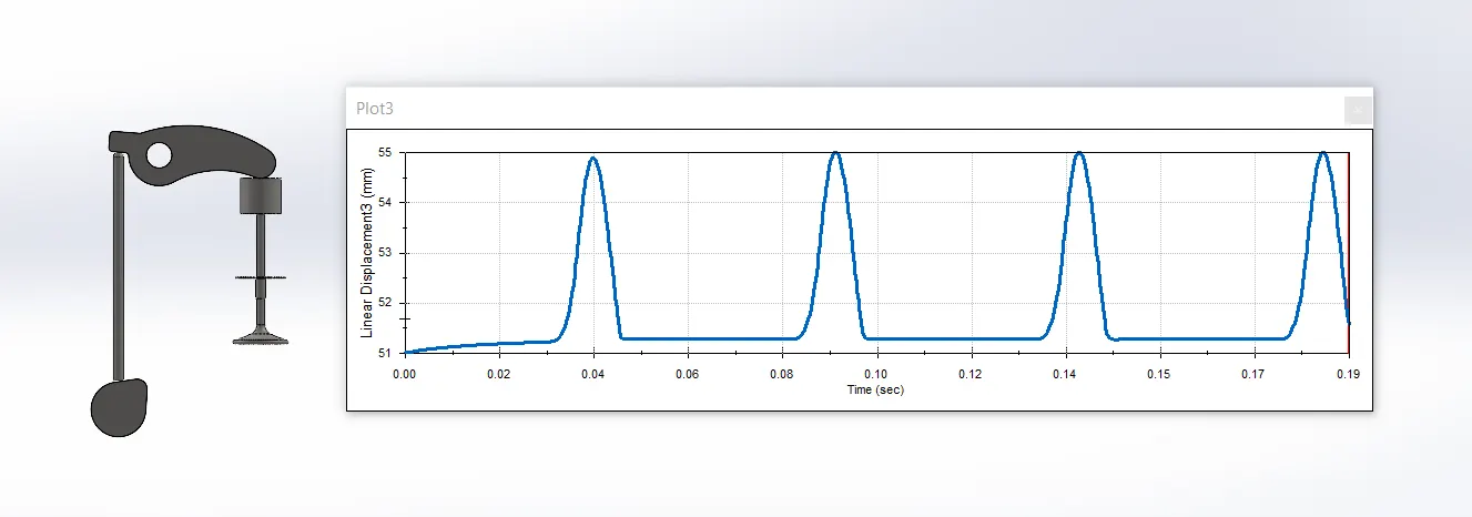
Case 2:
Displacement of Push Rod and Valve:
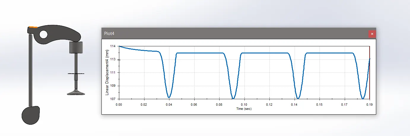
Conclution:
The valve train's components work together to ensure precise timing and coordination of the valve movements with the engine's piston movements, optimizing performance, fuel efficiency, and emissions. Proper maintenance and adjustment of these components are essential for the smooth operation and longevity of the engine.