MBD Simulation on IC Engine Valve Train
MBD Simulation on IC Engine Valve Train
Aim: To model and assemble the parts of IC Engine Valve Train and perform motion analysis simulation.
Introduction: A valvetrain is a component that is designed to open and close the intake and exhaust valves so that air/fuel mixture can enter and leave the combustion chamber as gases. It is consists of the following components-
- Cam
- Pushrod
- Rocker arm
- Valve
- Valve Stem
Problem Specification: Run the simulation using the below parameters
| Sl.No | CAM Lift (mm) | Speed (RPM) | Material |
| 1 | 3.5 | 1500 | Cast Carbon Steel |
| 2 | 6 | 1500 |
Cast Carbon Steel |
Obtain:
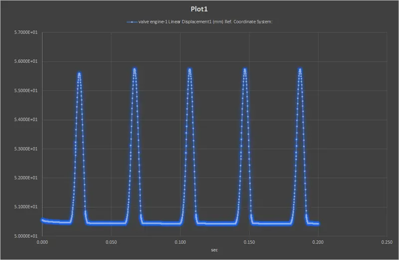
- Valve Lift.
- The contact force between
- Cam and Push Rod
- Pushrod and Rocker Arm
- Rocker Arm and Valve
Calculation:
Cam Lift formula- Cam Lift=L-R1+R2
where,
L =The distance between two centers.
R1=The Radius of the lower circle=12.5mm
R2=The radius of the upper circle=5mm
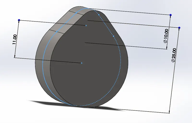
Case1- Cam lift =3.5 mm
Therefore L=3.5-5+12.5=11mm
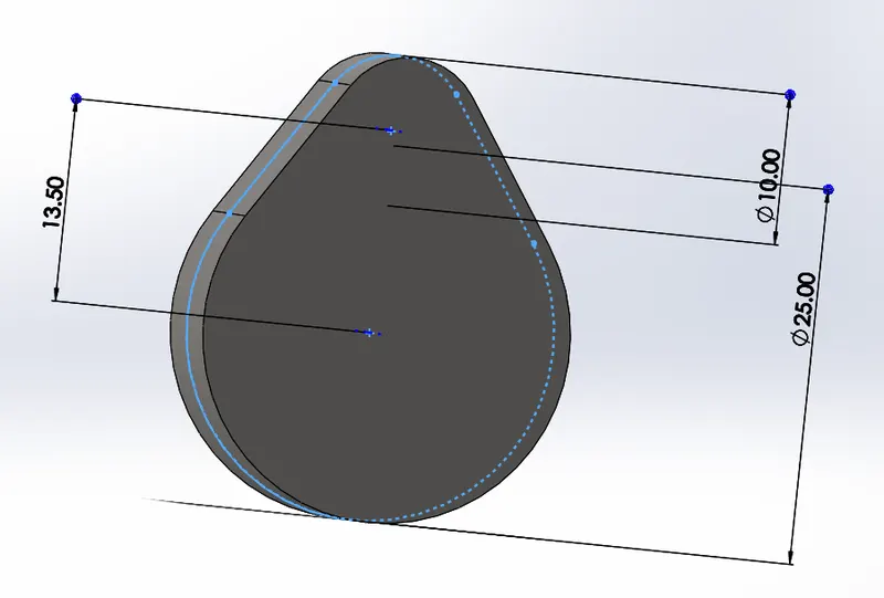
Case2- Cam lift =6 mm
Therefore L=6-5+12.5=13.5mm
Models:
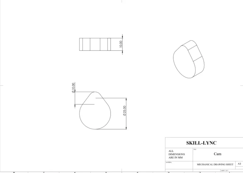
1 Cam:
Geometry:
MODELS:
STEPS TO CREATE MODELS
1) Draw the sketch as per geometry.
2) Provide Boss Extude about midplane 10mm.
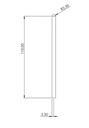
2 Pushrod:
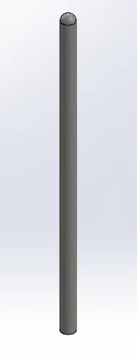
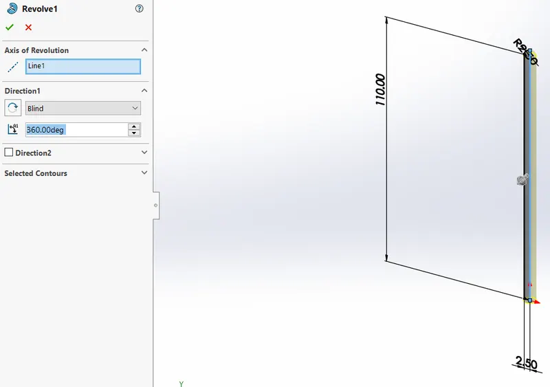
STEPS TO CREATE MODELS
1) Draw the sketch as per geometry.
2) Provide Revolve about the line as shown.
3 Rocker arm:
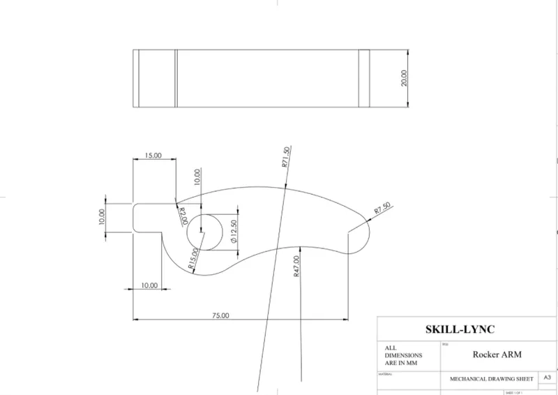
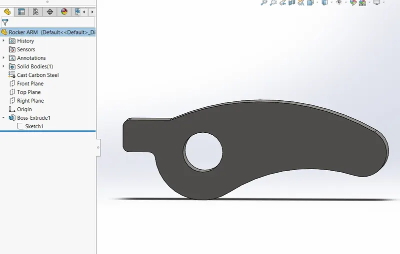
STEPS TO CREATE MODELS
1) Draw the sketch as per geometry.
2) Provide Boss Extude about midplane.
4 Valve:
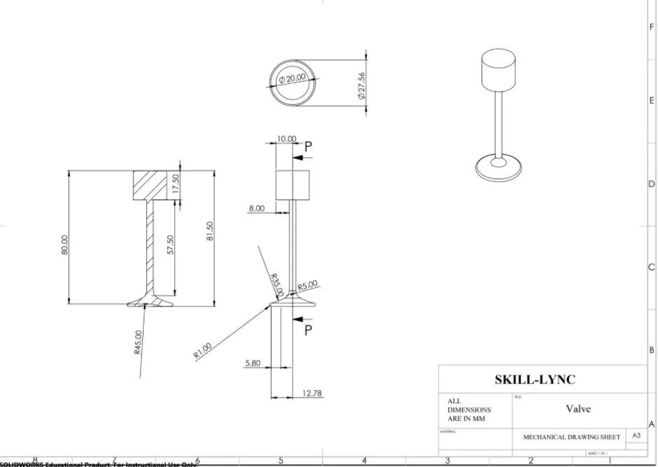
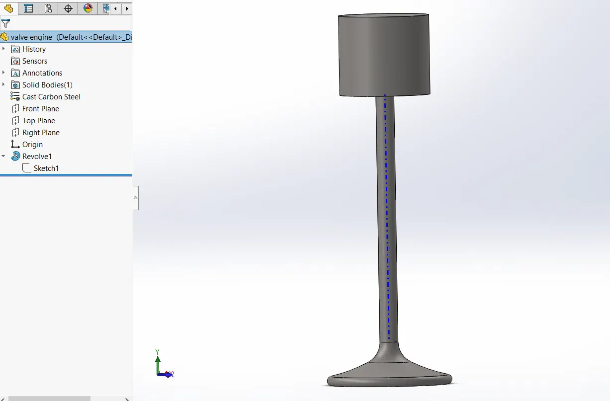
STEPS TO CREATE MODELS
1) Draw the sketch as per geometry.
2) Provide Revolve about the line as shown.
5 Valve mount:
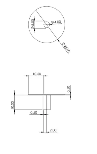
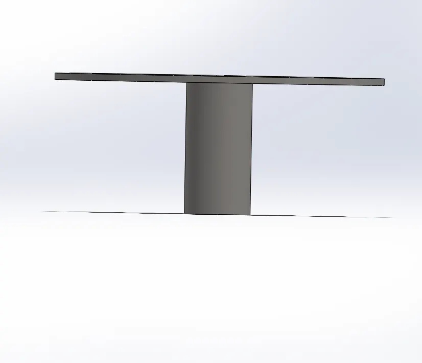
STEPS TO CREATE MODELS
1) Draw the sketch as per geometry.
2) Provide Revolve.
Assembly:
1)
2)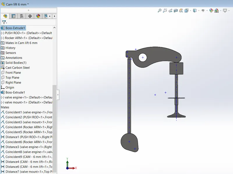
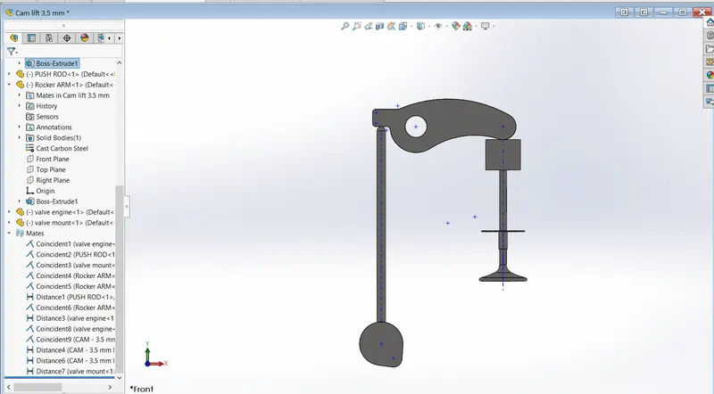
After making the models assembly is created using suitable mates as shown.
- Enabled Physical dynamics option.
- Provided the material cast carbon steel.
Motion Analysis Properties:
- Motor is provided at cam axis of 1500 RPM .
- Frames per second used=7200
- Precise contact enabled
- contact is solid body contact
- contact is solid body contact
- Simulation is run for 0.2 seconds
- spring stifness=10N/mm
- Pre tension in spring is of 10 mm
PLOTS:
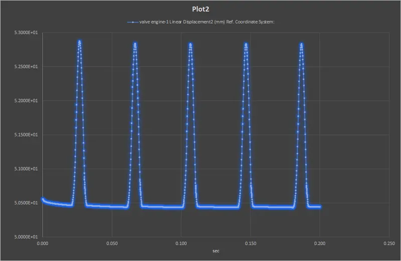
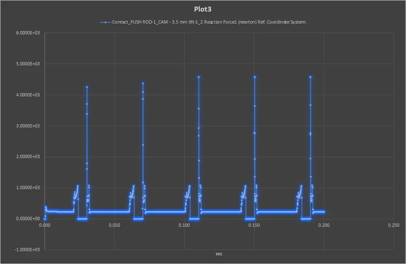
Case1) Cam Lift=3.5 mm
1) Valve Lift:
2)The contact force between
- Cam and Push Rod
- Pushrod and Rocker Arm
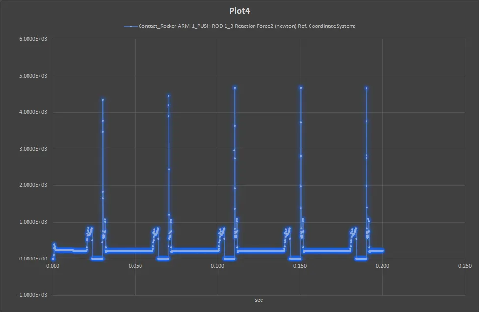
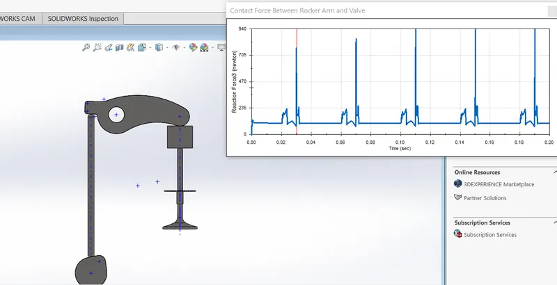
- Rocker Arm and Valve(Magnitude)
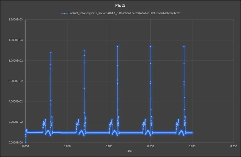
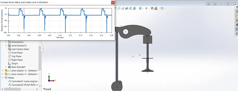
- Rocker Arm and Valve(x component)
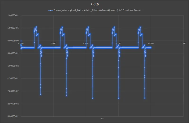
Case2) Cam Lift=6 mm
1) Valve Lift:
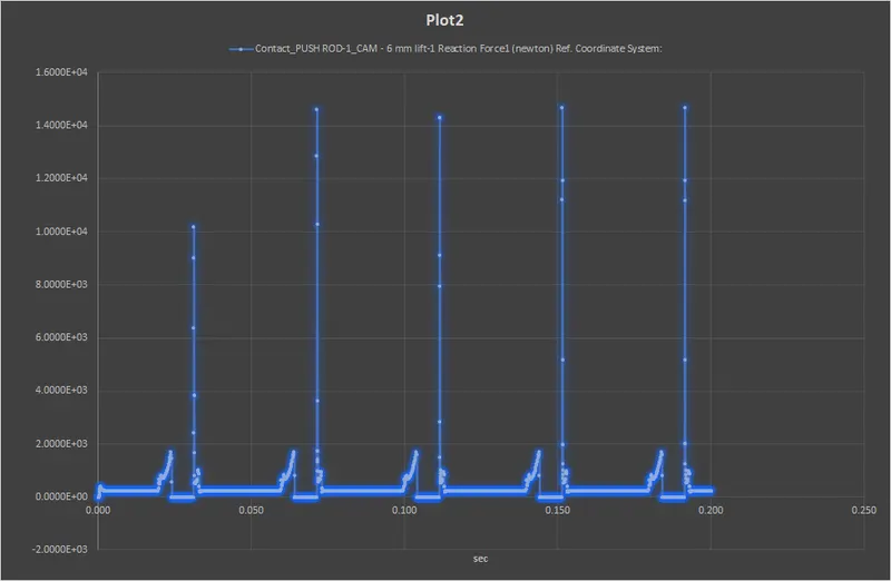
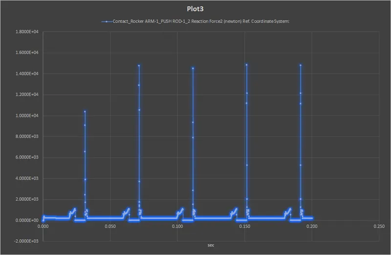
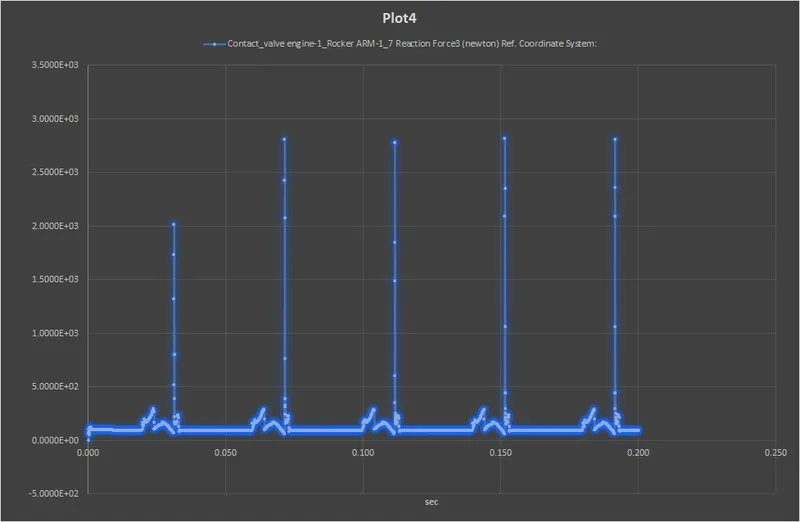
2)The contact force between
- Cam and Push Rod
- Pushrod and Rocker Arm
- Rocker Arm and Valve(Magnitude)
- Rocker Arm and Valve(x component)
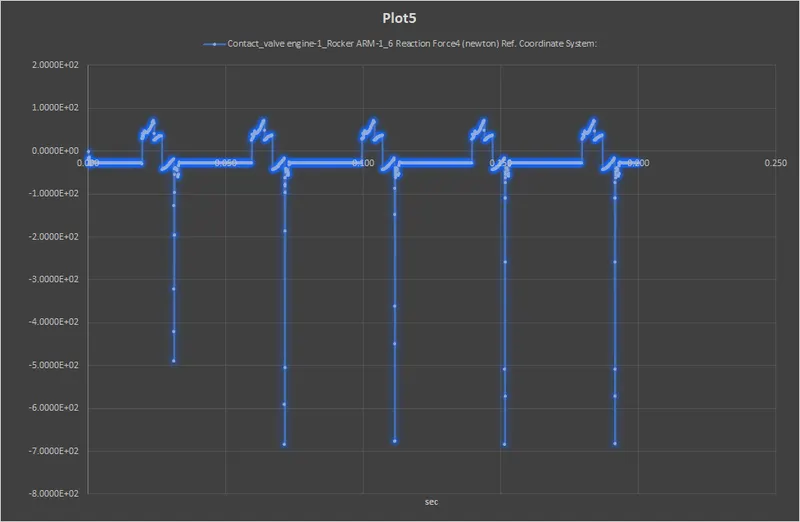
Result And Explanation:
The contact force magnitude between Rocker Arm and Valve varieses because of the movement of the cam when the cam lift is maximum contact force becomes maximum and varis accordingly for other positions.The spring also plays significant role in this.This is true for both the cases.
Animation:
1) https://drive.google.com/file/d/1B_yBAp2r2-M7coXRNygjz1Wpj9nRSyHJ/view?usp=sharing
2)https://drive.google.com/file/d/1JXvt5EmKekW-hfCODgmgJyjKA_Q06eF-/view?usp=sharing
FILES:
https://drive.google.com/drive/folders/15aU6eH15pOeJCI7NRYoPU5yWxLH9kdXV?usp=sharing