MBD Simulation on a Piston Assembly
PISTON ASSEMBLY SIMULATION
Aim: To model and assemble the parts of the piston assembly and run the motion analysis simulation.
Introduction: Piston assembly is used in engineering applications to convert rotatory motion to translatory motion or vice versa. It consists of the following parts-
- Piston
- Connecting Rod
- Crank
- End Cap
- Wrist Pin
Problem specification:
The motion analysis is going to be carried out in three different conditions,
| Sl.No |
Wrist Pin Offset ` |
Crank Speed (Rpm) |
| 1 | "0" mm | 2000 |
| 2 | 10 mm Positive | 2000 |
| 3 | 10 mm Negative | 2000 |
Models:
1) Piston:
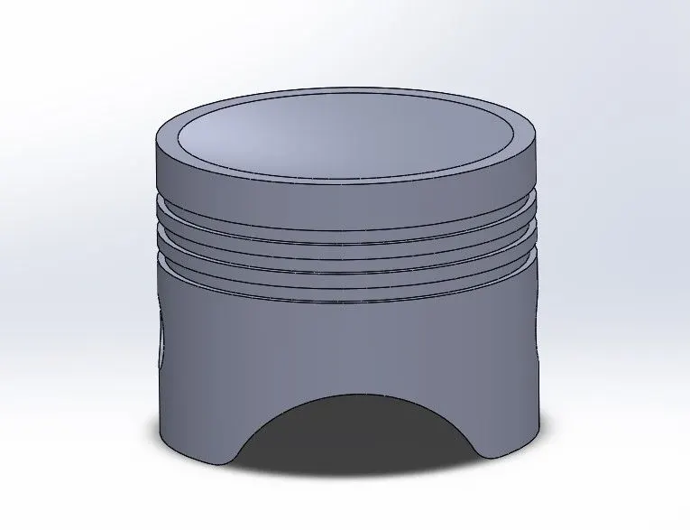
The piston is a component that slides back and forth due to the rotation of the crank. The model of the piston is created using the following geometry
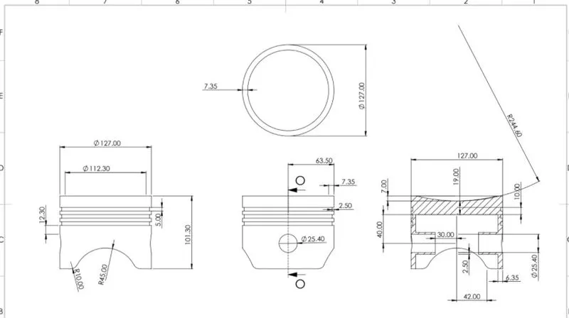
To create a 3D model of following steps have been taken
- Making the sketch on the plane.
- Adding the features like Revolve, Cut revolve, cut extrude, Boss extrude, Fillet.
2) Connecting Rod: A connecting rod also called a con rod, is the part of a piston engine that connects the piston to the crankshaft. Together with the crank, the connecting rod converts the reciprocating motion of the piston into the rotation of the crankshaft.
Geometry: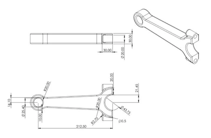
Model:
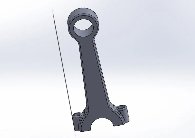
Using the given geometry the model has been created by making the sketch on the planes and then adding features like Boss extrude and Cut extrude. A suitable fillet is provided.
3) Crank: A crank is an arm attached at a right angle to a rotating shaft by which a circular motion is imparted to or received from the shaft. When combined with a connecting rod, it can be used to convert circular motion into reciprocating motion, or vice versa. The arm may be a bent portion of the shaft or a separate arm or disk attached to it. Attached to the end of the crank by a pivot is a rod, usually called a connecting rod.
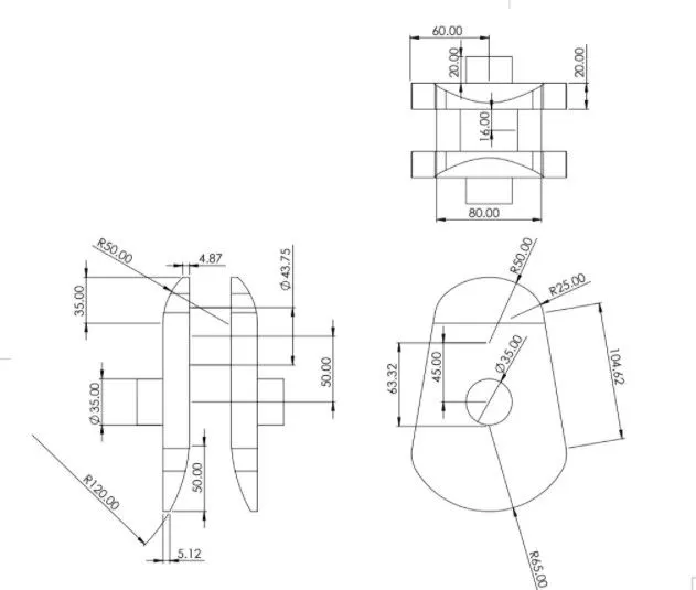
Model:
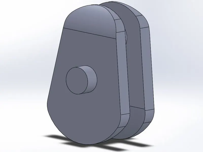
Using the given geometry the model has been created by making the sketch on the planes and then adding features like Boss extrude and Cut extrude and mirror. A suitable fillet is provided.
4) End Cap: It is used to close the connecting rod end.
Geometry:
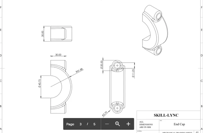
Model:
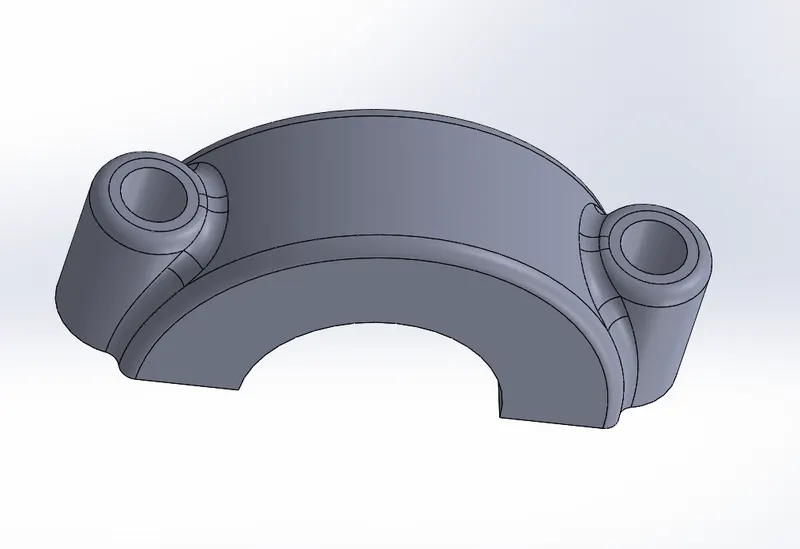
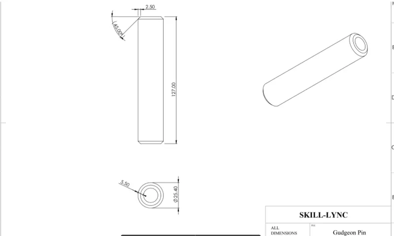
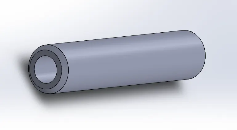
5)Wrist Pin: A wrist pin is a pin through the skirt of a piston in an internal-combustion engine, to which the little end of the connecting rod is attached.
Geometry:
Model:
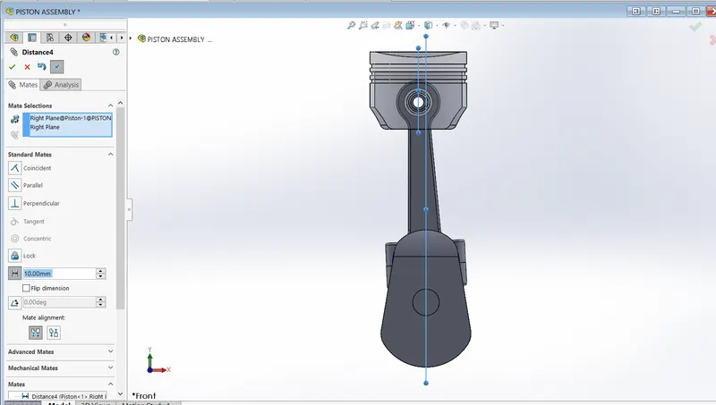
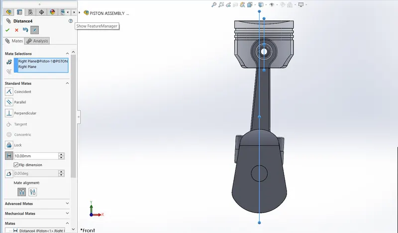
Assembly: After making the models assembly is created using suitable mates.
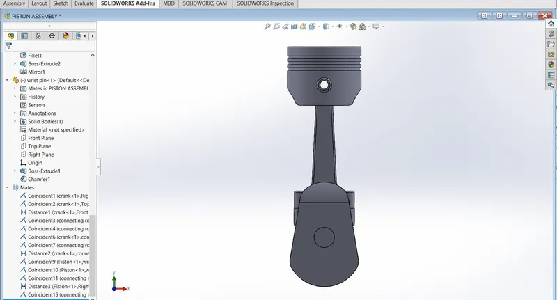
1 0 offset
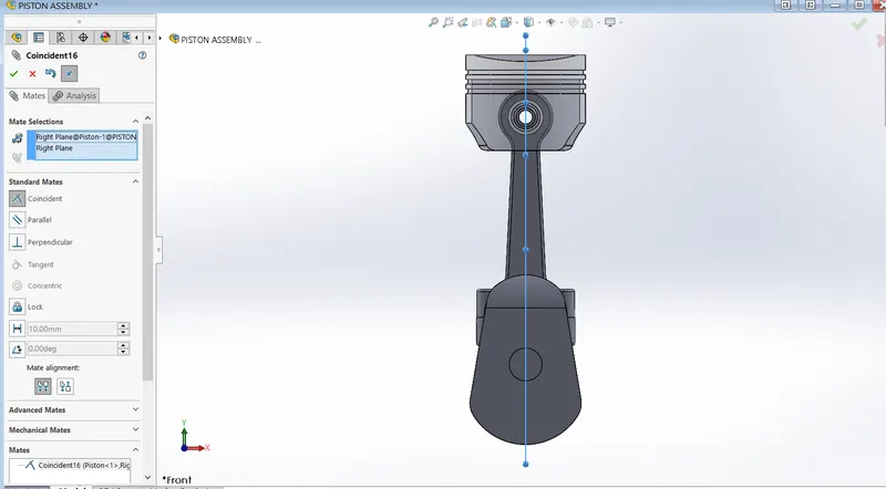
10 mm positive offset
10 mm negative offset
Motion Analysis Simulation:
- Provided motor into crank of 2000 RPM
- Contact is solid body contact between the surfaces and material is dry steel
- Gravity is in Y direction
- 8400 frames per second and precise contact is used.
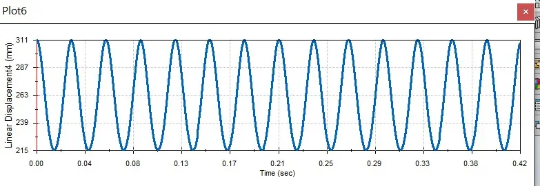
Result and plots: Linear displacement of piston is plotted in three different given comdition.
1) 0 mm offset
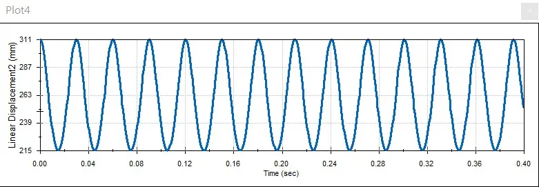
2) 10 mm positive offset
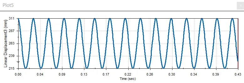
3) 10 mm negative offset
Conclusions:
- There is only a slight difference between the plots.
- Having an offset pin relieves the stress that is caused in the rod when it reaches the top or bottom dead center
- the plot is between linear displacement vs time.
- In all the plots 311 mm is the starting point.
Animations:
1 https://drive.google.com/file/d/1vEmHbl0S8MjAY57oL0VaHR9YbxaccXPK/view?usp=sharing
2 https://drive.google.com/file/d/1NhPKqNVQlQXC_LquhY9YTvuP_qaozZwM/view?usp=sharing
3 https://drive.google.com/file/d/1eElU5bA_sIamlsvT0KnO9AVTdHSxSHNM/view?usp=sharing
FILES:
https://drive.google.com/drive/folders/1rrJ4GhNW8rJgZNIT2f1cm04HjhvZ8uTw?usp=sharing