MBD Simulation on a Piston Assembly
Exercise:
Model all the parts and then assemble them in SolidWorks. The motion analysis is going to be carried out in three different conditions,
| Sl.No |
Wrist Pin Offset ` |
Crank Speed (Rpm) |
| 1 | "0" mm | 2000 |
| 2 | 10 mm Positive | 2000 |
| 3 | 10 mm Negative | 2000 |
Wrist Pin Offset - The position of the wrist pin is going to be varied as followed. But the center of the axis of the piston head and the crank are coincident to each other (i.e) They are on the same plane in all the three cases.
"0" mm Offset - Run a simulation as seen in the video.
10 mm Positive Offset - If the crank rotation is in the Clockwise direction
10 mm Negative Offset - If the crank rotation is in the Clockwise direction.
AIM
To model all the parts of piston assembly and then assemble them in solidworks and run motion analysis.
OBJECTIVES
-
To model all the components of piston assembly
-
To make assembly of the piston.
-
To do motion analysis for three different cases
-
To Obtain the Linear displacement of the Piston Head in all the three cases.
-
Then Export the data to excel and create the three plots and then Superimpose all the three graphs into a single graph.
CASE:
|
Sl.No |
Wrist Pin Offset |
Crank Speed (Rpm) |
|
1 |
"0" mm |
2000 |
|
2 |
10 mm Positive |
2000 |
|
3 |
10 mm Negative |
2000 |
- "0" mm offset - if the crank rotation is in the clockwise direction.
- "10" mm positive offset - If the crank rotation is in the clockwise direction
- "10" mm negative offset - If the crank rotation is in the clockwise direction.
THEORY
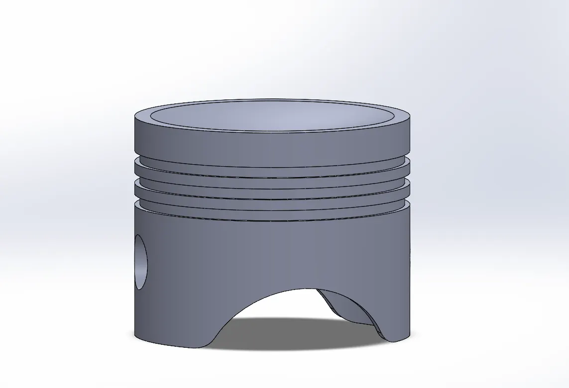
1. Piston
- A cylindrical element moving back and forth within the cylinder, harnessing energy from fuel combustion to set the crankshaft in motion.
- Features grooves near the top for an air-tight seal, preventing high-pressure combustion mixtures from entering the crankcase.
- Executes four strokes - two upward (compression and exhaust) and two downward (intake and power).
2. Connecting Rod:
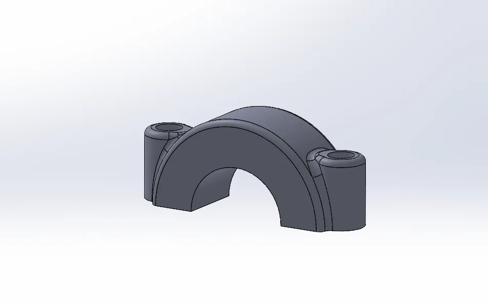
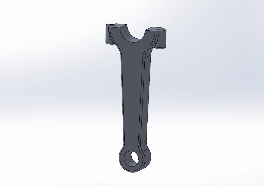
- Serves as the vital link between the piston and crankshaft.
- Upper end, connected to the piston through the wrist pin, has a hole.
- The lower end (big end) attaches to the crankshaft, while the small end allows swiveling within the piston.
- Crafted from materials like alloy steel, titanium, and occasionally aluminum.
- Designed to adapt to dynamic movements, avoiding rigidity at either end.
3. Crankshaft:
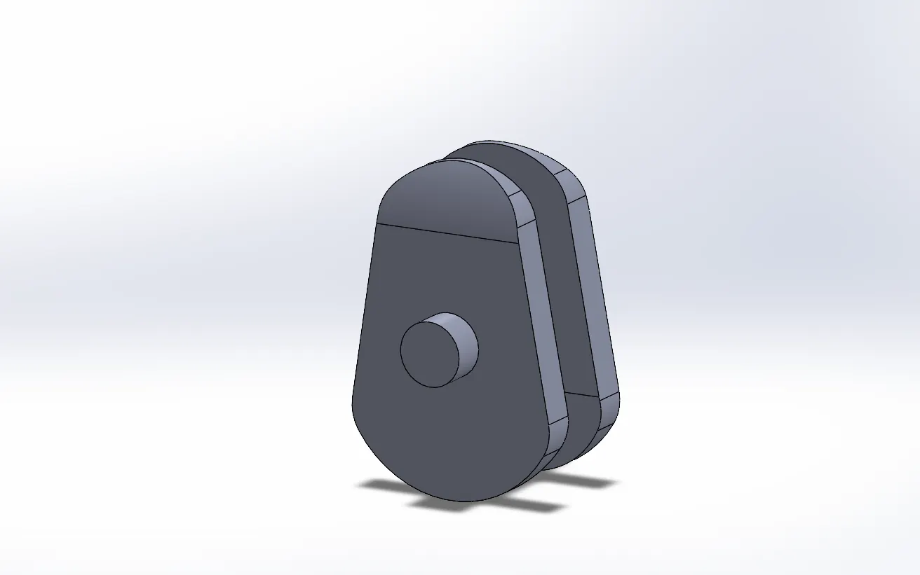
- Transforms the reciprocating motion of pistons into a rotational force for the wheels.
- Typically composed of alloy steel or cast iron.
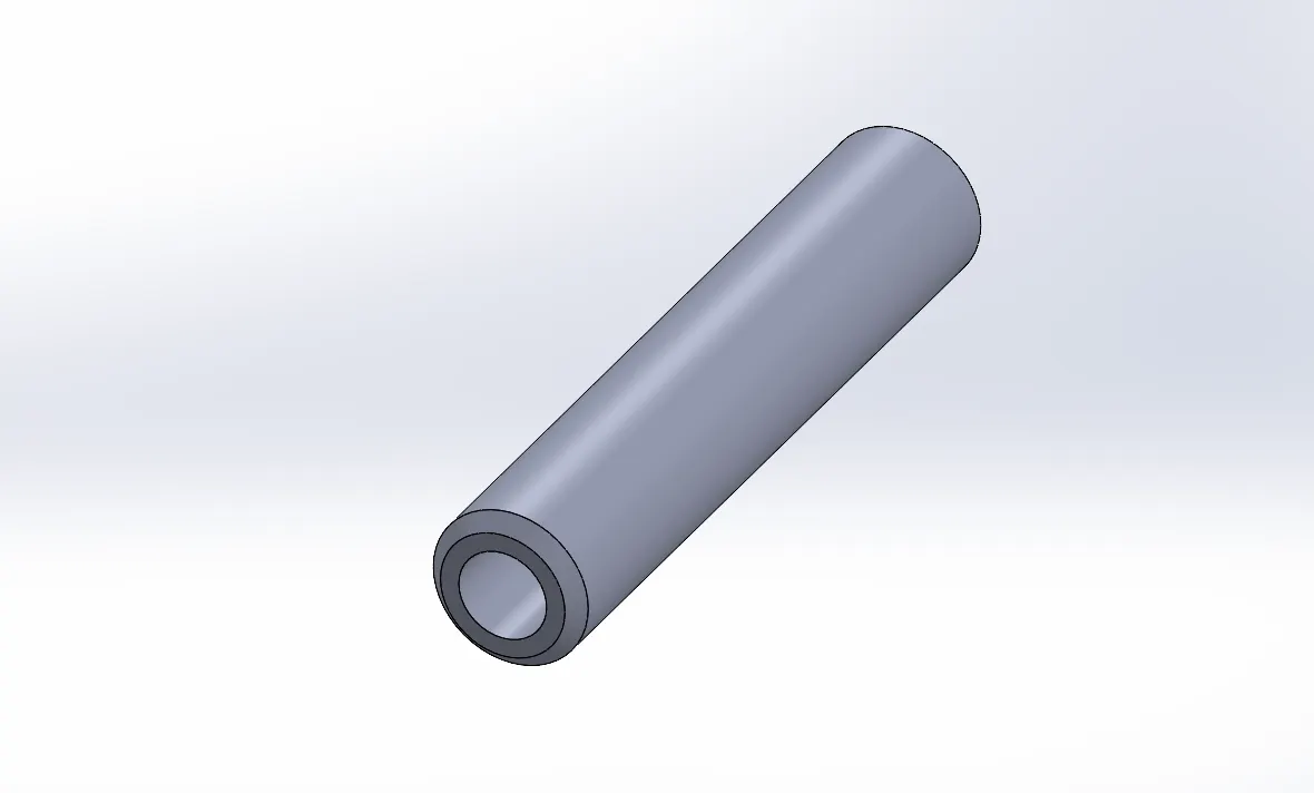
4. Gudgeon Pin:
- Links the piston to the connecting rod, ensuring a smooth pivot for the connecting rod as the piston moves.
- Plays a crucial role in maintaining the seamless motion of the piston.
Assembly:
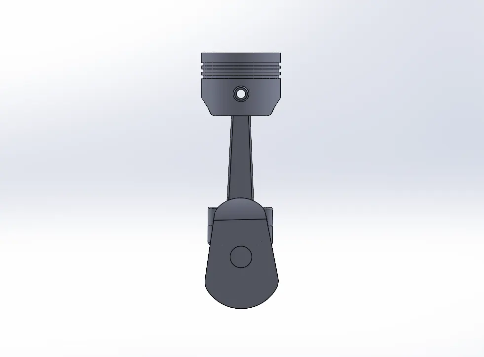
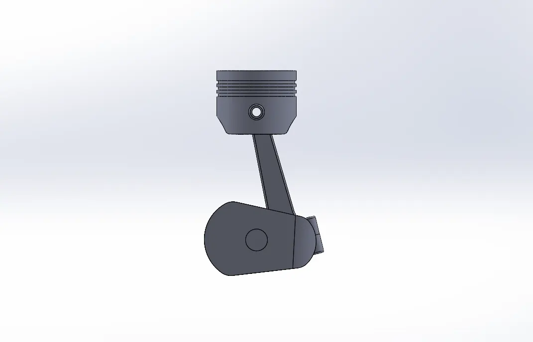
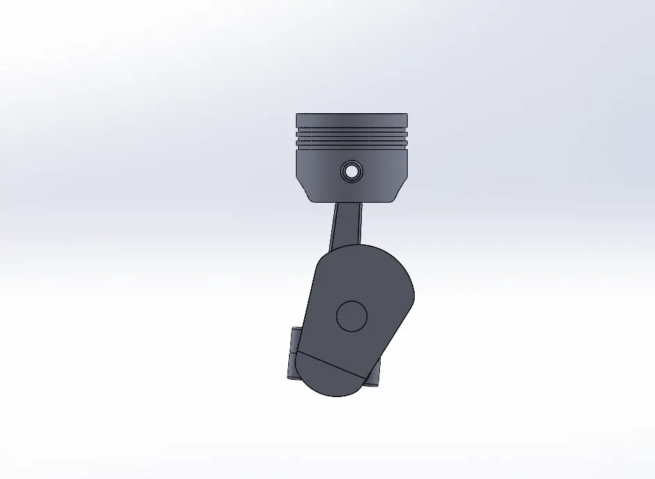
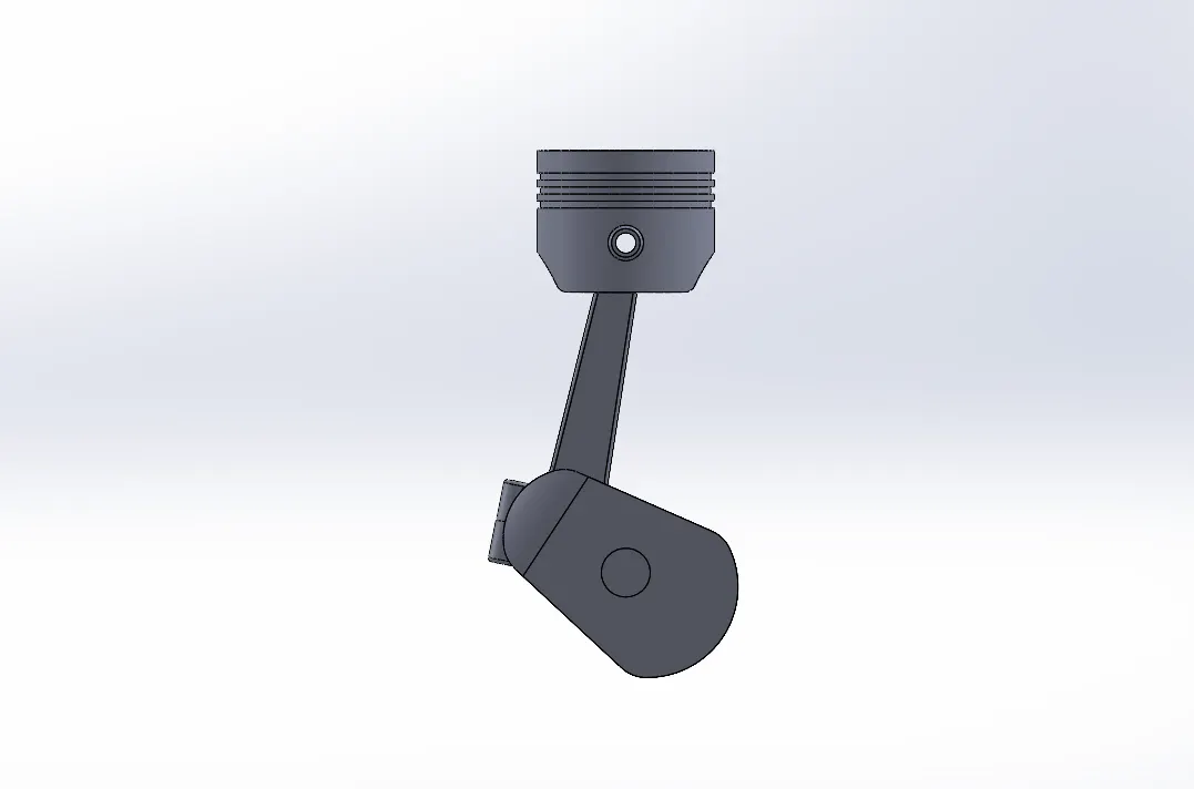
The assembly process commences with the integration of the modeled components. Initially, the crankshaft is inserted, with its axis aligned coincidentally to the top and right planes. The front plane of the crankshaft is then deliberately positioned at a specified distance from the assembly's front plane, allowing for subsequent adjustments.
Following this, the connecting rod and end cap are introduced into the assembly. The axes of these components are synchronized, and their faces are aligned to ensure synchronous movement. Notably, the crankshaft's axis is made coincident with that of the connecting rod.
To allow for clearance, a meticulous approach is taken. One side of the connecting rod is meticulously chosen, and its corresponding side on the crankshaft is made coincident, introducing a deliberate 1 mm distance mate to afford necessary space.
The assembly process continues with the insertion of the piston head and wrist pin. These components are meticulously aligned along their respective axes and planes. The axis of the wrist pin is made coincident with that of the connecting rod, and the front plane of the connecting rod is precisely aligned with the front plane of the piston head. Finally, the right plane of the piston is brought into coincidence with the assembly's right plane, completing the intricacies of the assembly process.
Motion Analysis:
Following the meticulous and accurate assembly process, we proceeded to conduct motion studies using SolidWorks add-ins, examining the scenarios outlined in the challenge statements.
- "0" mm offset - if the crank rotation is in the clockwise direction.
A torque/motor was applied to the crank axis, set at 2000 rpm in a clockwise direction. Solid body contacts were established for various components, specifying steel (Dry) as the material. Gravity was defined in the downward direction (Y-axis), and precise contact conditions, along with a velocity of 12000 fps, were input for accurate and smooth calculations.
The resultant plot displays the linear displacement of the piston as derived from the analysis.
2.)"10" mm positive offset - If the crank rotation is in the clockwise direction
A torque/motor was applied to the axis of the crank at 2000 rpm in a clockwise direction. Solid body contacts were established for various components, specifying steel (Dry) as the material. Gravity was defined in the downward direction (Y-axis), and a 10 mm offset was introduced for the hole position in the piston head. Precise contact conditions and a velocity of 12000 fps were set as input parameters to ensure smooth calculations.
The resulting plot illustrates the linear displacement of the piston obtained from the simulation results.
3.)"10" mm negative offset - If the crank rotation is in the clockwise direction.
A torque/motor was applied to the axis of the crank at 2000 rpm in a clockwise direction. Solid body contacts were established for various components, with steel (Dry) chosen as the material. Gravity acted in the downward direction (Y-axis), and a 10 mm offset was introduced for the hole position in the piston head. Precise contact conditions and a velocity of 12000 fps were specified as inputs to ensure smooth calculations.
The resulting plot illustrates the linear displacement of the piston obtained from the simulation results.
Conclusion:
Successfully modeling the piston components and assembling them is a commendable achievement. The linear displacement graphs for the three different cases provide valuable insights into the motion of the piston from Top Dead Center (TDC) to Bottom Dead Center (BDC).In scenarios where the piston pin aligns with the center of the piston, encountering TDC or BDC places a significant load on the rod. The crank must rotate past TDC or BDC to restart piston movement, resulting in a substantial power and RPM loss for the engine.However, employing an offset pin configuration mitigates these challenges. The offset piston wrist pin ensures that the rod is not vertically aligned when the piston is at TDC or BDC. This minimizes resistance during crank rotation, translating to increased engine power and speed.The offset pin configuration proves advantageous by alleviating stress on the rod during TDC or BDC, eliminating the need for the rod to forcefully propel the piston upwards and downwards. Instead, the rod follows a more arced trajectory, contributing to smoother engine operation and enhanced performance.
Refer:
Chatgpt
skill-lync.com