MBD Simulation on a Piston Assembly
MBD Simulation on a Piston Assembly
AIM:-
- Create the parts and assembly of the piston and motion analysis of piston assembly.
OBJECTIVES
- To create the 3d model of the parts and assemble the parts to make a mechanism.
- To motion analysis of the piston assembly.
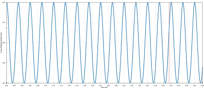
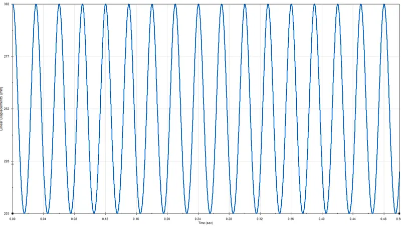
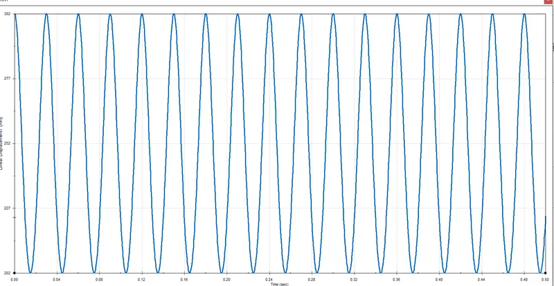
- To plot the Linear Displacement of the piston head.
- To plot the graphs for 0mm offset, 10mm positive offset and 10mm negative offset.
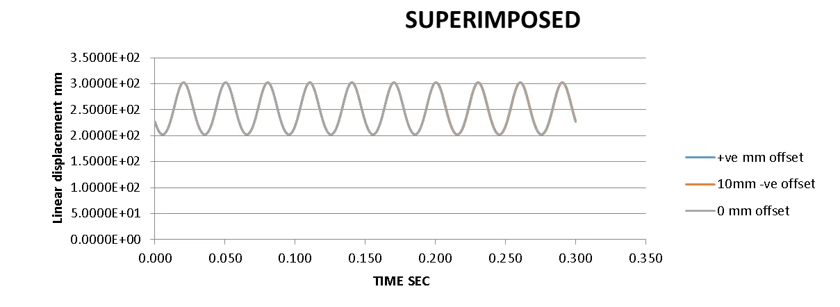
- To superimpose all three graphs into one graph.
THEORY
A piston is a component of reciprocating engines, reciprocating pumps, gas compressors and pneumatic cylinders, among other similar mechanisms. It is the moving component that is contained by a cylinder and is made gas-tight by piston rings. In an engine, its purpose is to transfer force from expanding gas in the cylinder to the crankshaft via a piston rod and/or connecting rod. In a pump, the function is reversed and force is transferred from the crankshaft to the piston for the purpose of compressing or ejecting the fluid in the cylinder. In some engines, the piston also acts as a valve by covering and uncovering ports in the cylinder.
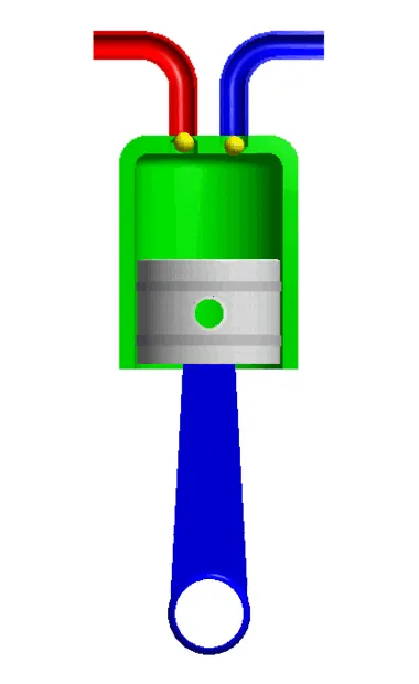
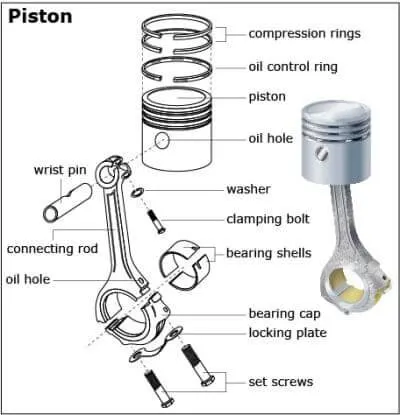
PISTON ASSEMBLY
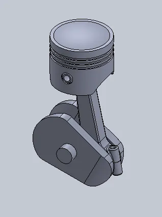
- Piston assembly consists of a piston, piston rings and piston pin known as gudgeon pin. Functions of piston assembly are given below:
- It transmits gas force generated during combustion to the connecting rod and crankshaft.
- As piston is connected to small end of the connecting rod with the help of gudgeon pin. It guides the connecting rod when gas force is transmitted.
- Air/fuel mixture is compressed by piston.
- Piston rings restrict the flow of hot gases into the crankcase. This is also referred as blow by control.
- Piston rings lubricate the cylinder wall.
- Piston rings restrict the amount of oil from crankcase into the gap between piston and cylinder head.
- Heat is transferred to the cylinder wall from piston by piston rings.
piston construction
The construction of a piston. Piston top is the part of combustion chamber. Top portion can be a flat or bowl is provided as per the combustion requirement. Grooves are provided in the ring belt area to accommodate piston rings. The heat flows from crown, out of the ring belt. Heat is transferred to the cylinder walls through piston rings and then small portion is transferred to the skirt. Some amount of heat is also taken by the lubricant.
Piston rings
There are two types of piston rings: compression and oil control ring. Piston rings are generally made up of rectangular section. To prevent sticking of ring into the groove, their inner and outer edges are chamfered. Compression rings are subjected directly to gas pressure.
Gudgeon Pin or piston pin
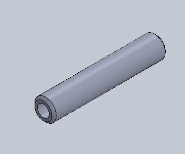
Gudgeon pin is the main load carrying part in piston assembly. Small end of the connecting rod is connected to piston with the help of gudgeon pin as shown in fig 2.2.It consists of aluminum pads are placed at the ends; these will not damage the cylinder. In order to maintain a correct fit between piston and connection rod, external surfaces of gudgeon pins are finished to a high degree of accuracy.
CONNECTING ROD
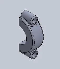
The main function of a connecting rod is to form a link between a piston and crankshaft. A small end of the connecting rod is connected to the piston with gudgeon pin and big end is separated into two parts for ease of assembly with crankpin. The two parts of the big end are bearing cap and big end housing. Both are being bolted together. This is done for ease of assembly of connecting rod with crankpin. To supply oil to the big end, the oil hole is drilled from big end. A typical arrangement of connecting rod is given below:
CRANKSHAFT
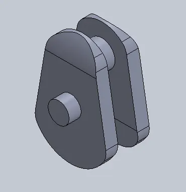
Crankshaft is the final link in the slider crank mechanism. The linear motion of a piston is converted into rotary motion of a crankshaft. The energy is generated into the combustion chamber by transforming the reciprocating motion of a piston into rotary motion of a crankshaft. Crankshaft consists of two main bearings at the other side of the it, made up in to two half liners. Crankshaft, crankshaft oil seals, main bearings, pulley and vibration damper are parts of crankshaft assembly.
The motion analysis is carried out on three different conditions
| Sl.No |
Wrist Pin Offset |
Crank Speed (Rpm) |
| 1 | "0" mm | 2000 |
| 2 | 10 mm Positive | 2000 |
| 3 | 10 mm Negative |
2000 |
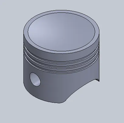
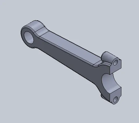
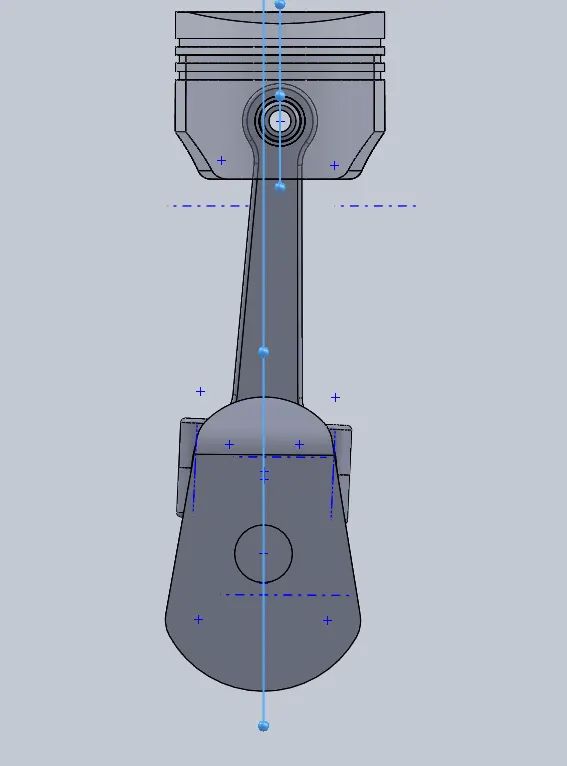
The different parts involved in our assembly are as follows
Piston
Connecting Rod:
END CAP :
Gudgeon Pin:
Crank:
THE ASSEMBLY PART:
Motion Study Analysis
The motion study: In the Motion study the following steps are performed.
- Motor is given to crank with the speed 2000 RPM in clockwise direction.
- Frames per second are given as 7200 with precise contact.
- Contact is given between endpin and crank, crank and connecting rod, connecting rod and wrist pin and wrist pin and piston.
- The material selected for each case is steel (Dry).
- Gravity in the Y direction(Downward).
The graph obtained on performing the Motion analysis of this assembly:
0mm Offset
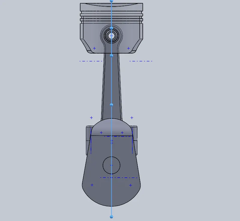
10 mm Positive Offset
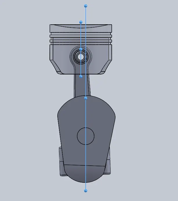
10 mm Negative Offset
Conclusion and observation:
- As observed form the above graphs the linear displacement remains almost same in all the three cases.
- we can see the difference in the linear displacement, so we can say that by offsetting the piston pin, we can avoid the over traveling of the piston.
- From the plots obtained, we can see that Linear Displacement increases as we move from negative wrist pin offset to positive wrist pin offset i.e. the magnitude of the Linear displacement increases.
- Also from the graph obtained after superimposing it we can see that for a given time frequency of rotation of piston with wrist pin offset negative is higher comparatively to one with zero offset and pin with zero offset has higher frequency than one with a positive offset.