Mathematical Model of a Battery
OBJECTIVE:
To run a MATLAB script for the mathematical model of lead acid battery and draw some conclusions based on simulation results.
SOLUTION TO THE OBJECTIVE:
Brief Information about the Lead-Acid Battery
A Lead-Acid Battery (PbA) is a type of an electrochemical Battery which can be repeatedly charged and discharged. This Battery can be used in Automotive Powertrain applications.
This Battery generally has an anode plate made of Lead (Pb) and a cathode plate covered with Lead Dioxide (PbO2) and an electrolyte comprising of a solution of Sulphuric Acid (H2SO4) and water. During Charging/discharging of the Battery, electrochemical reactions or more specifically redox reactions take place where a Voltage of approximately 2 Volts is generated per Lead-Acid Cell.
As electricity gets generated, a process called ‘sulphation’ takes place which causes Lead Sulphate (PbSO4) to coat the electrode plates. As Battery is discharged, the Voltage of the Battery/cell drops due to the sulphation process. On recharging the Battery, Lead Sulphate again gets converted back to Lead (Pb) and sulphuric acid (H2SO4).
|
Battery Chemistry |
State of Battery |
Electrode |
Reaction Type |
Equation |
Voltage(V) |
|
Lead-Acid (PbA) |
Charging |
Cathode |
Oxidation |
PbSO4 + 2H2O -> PbO2 + H2SO4 + 2H+ + 2e- |
1.69 |
|
Lead-Acid (PbA) |
Charging |
Anode |
Reduction |
PbSO4 + 2H+ + 2e– -> Pb + H2SO4 |
-0.36 |
|
Lead-Acid (PbA) |
Charging |
Cell |
2PbSO4 + 2H2O -> Pb + PbO2 + 2H2SO4 |
2.05 |
|
|
Lead-Acid (PbA) |
Discharging |
Cathode |
Reduction |
PbO2 + H2SO4 + 2H+ + 2e– -> PbSO4 + 2H2O |
1.69 |
|
Lead-Acid (PbA) |
Discharging |
Anode |
Oxidation |
Pb + H2SO4 -> PbSO4 + 2H+ +2e– |
-0.36 |
|
Lead-Acid (PbA) |
Discharging |
Cell |
Pb + PbO2 + 2H2SO4 -> 2PbSO4 + 2H2O |
2.05 |
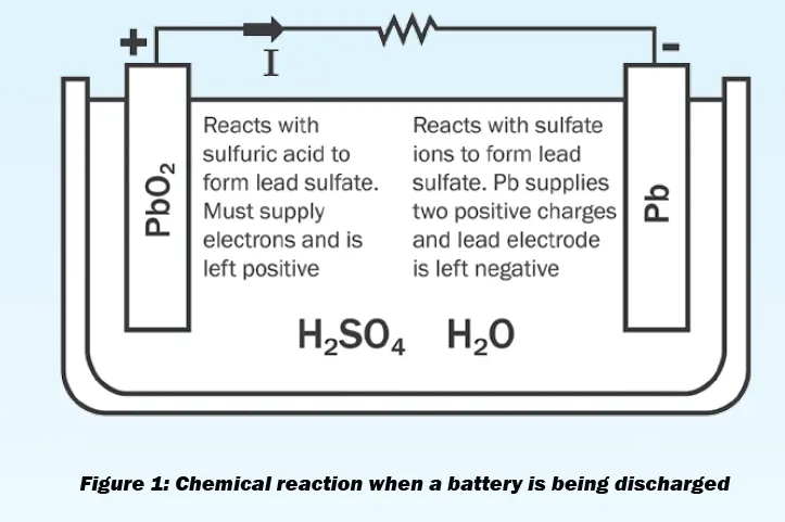
Lead Acid Battery mechanism during Discharging state
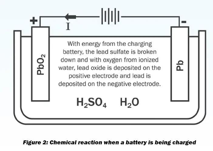
Lead Acid Battery mechanism during charging state
In general, Lead-acid Batteries are a good choice for starter Batteries for conventional vehicles due to its low internal resistance, high cranking current, low costs and recyclability.
Battery Modelling:
The battery model used for this objective is an empirical model. Empirical models are used to analyse and describe the performance of the battery using arbitrary mathematical relationships which somewhat matches with experimental or theoretical data obtained after conducting lab tests with the battery. The empirical models, though having many drawbacks, can be very useful for quick estimation of range of an electric vehicle for a particular type of battery pack.
Assumptions for the Battery Model for this Objective:
- The Battery is discharged at a constant current.
- The Battery is discharged at a constant temperature.
- The battery is discharged up to the cut-off voltage limit.
- Aging of the Battery is not considered.
- The internal Resistance of the battery/cell is constant.
- The model doesn't provide the terminal I-V characteristics of the Battery/Cell which is necessary in Circuit simulation and Analysis for Hybrid and Electric Vehicles.
- This model doesn't take into consideration other factors affecting the Voltage of the Battery like the self-discharge rate of the Battery.
The analysis & behaviour of the battery model under consideration will be done using Peukert’s model of Battery Behaviour. The Peukert’s model, although not very accurate at low currents, can predict the behaviour of a battery model operating at high levels of current quite effectively. The Peukert’s equation can be mathematically defined as follows:
Cp = Ikt ____________________________________ (a)
Where Cp -> Capacity of the cell/battery when it is discharged at the rate of 1 Amperes. Unit -> Ampere Hours (Ah)
I -> Current discharged from the Battery. Unit-> Amperes (A)
t -> Time required to discharge the Battery. Unit-> Hours
k -> Peukert’s Coefficient. Unit-> Dimensionless.
I have used a real-life Battery Model to compare it’s parameters & characteristics to the model established using Peukert’s equation and its’ related parameters.
The Datasheet used as reference is attached in the following link:
https://drive.google.com/file/d/1DIu_dfy4QL9616QNQKLjtRqPvXB4wrhn/view?usp=sharing
In general, in the data sheet of a Battery, there are at least 2 rated capacities of the Battery mentioned. In the model under consideration for this objective, the Battery capacities (in Amp-hours) are mentioned for 10 hour discharge rate and for 3 hour discharge rate.
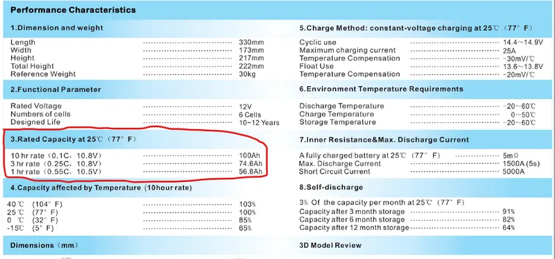
Using any 2 of these rated Battery Capacities, the ‘Cp’ and ‘k’ of the Peukert’s equation can be found out.
‘k’ or the Puekert’s coefficient is greater than 1 and by how much it is greater than 1 gives an indication about the extra current that needs to flow in the circuit due to the internal resistance of the battery.
Under the Rated Capacity, the Battery Capacity is mentioned as 100 Ah when discharged at 10 hour Discharge Rate. Therefore the total current that the 100 Ah rated battery can deliver over 10 hours:
I1 = Q1(rated)/t1
I1 = 100/10 = 10 Amperes
Where I1 -> Total current delivered by the Battery over the entire discharge period.
Q1(rated) -> Rated Battery Capacity for a given discharge rate.
t1 -> Total Time taken for the Battery to discharge upto the cut-off Voltage Limit.
Similarly, under the Rated Capacity specification, another Battery Capacity is mentioned as 74.6 Ah when discharged at 3 hour Discharge Rate. Therefore the total current that the 74.6 Ah rated battery can deliver over 3 hours:
I2 = Q2(rated)/t2
I2 = 74.6/3 = 24.866 Amperes
Where I2 -> Total current delivered by the Battery over the entire discharge period.
Q2(rated) -> Rated Battery Capacity for a given discharge rate.
t2 -> Total Time taken for the Battery to discharge upto the cut-off Voltage Limit.
Now, the Peukert’s Coefficient can be calculated using the following relation:
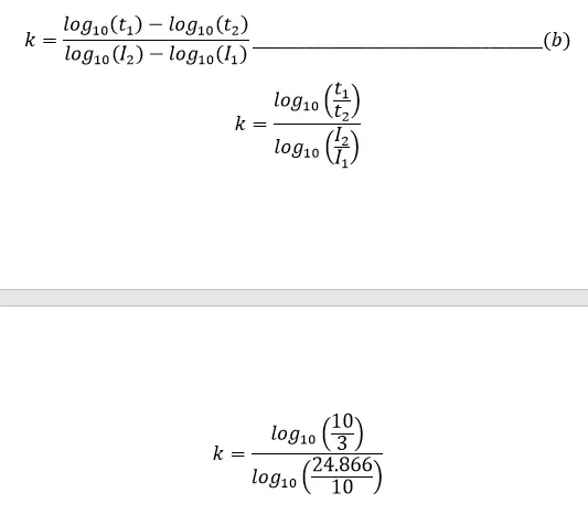
k = 1.3217
Therefore, the Peukert’s coefficient (k) = 1.3217.
Now, the Peukert’s Capacity (Cp) can be found out:
Cp = I1k t1 = 10(1.3217) X 10 = 209.74 Ah
Or
Cp = I2k t2 = 24.866(1.3217) X 3 = 209.74 Ah
Therefore, the Peukert’s Capacity has been found out to be equal to 209.74 Ah.
For this battery model, the equivalent circuit in which the battery is operating is considered as follows:
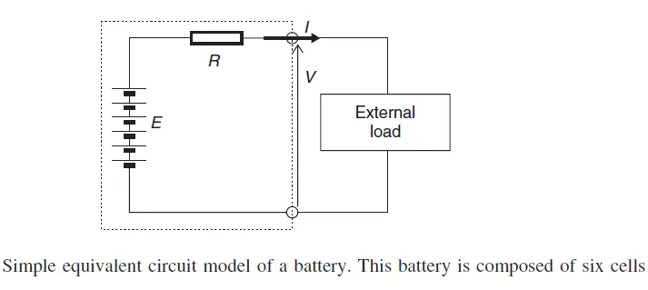
For this model, the internal resistance of the battery is also considered. For this, another empirical formula for calculating the internal resistance of the Battery (specifically applicable for Lead-Acid Batteries) is applied:
Rin = n X [0.022/Q (at 10 hour rate)]____________________________________ (c)
where n-> Number of cells in the Battery
Rin -> Internal Resistance of the Battery
Q(10 hr. rate) -> Amp-hour Capacity of the Battery at 10 hour rate
For this particular model, the internal resistance for the battery, considering the battery to be discharged fully (to cut-off Voltage Limit) at 3 hours.
Rin = 6 X [0.022/100]
Rin = 0.00132 Ω = 1.32 mΩ
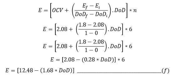
For finding out and plotting the actual Discharge Open Discharge Voltage Characteristics (Open Discharge Voltage vs DoD/SoC curve), another empirical formula (specifically applicable for Lead-Acid Batteries) is used:

where n -> Number of Cells used in Battery
OCV -> Open Circuit Voltage of the CELL at fully Charged Condition (DoD = 0)
E -> Battery Terminal Voltage at no load condition.
Ef & Ei -> Terminal Voltage of the CELL at final state and initial state respectively (both at no load condition)
DoD -> Depth of Discharge of the CELL
DoDf & DoDi -> Depth of Discharge of the CELL at final state and initial state respectively.
The above equation represents a straight line of the form y=mx + c. In general, experimental data for sealed Lead-Acid Batteries have shown Open Circuit Voltage (OCV) varies proportionally with State of Charge (SoC) for sealed Lead Acid Batteries to quite a good approximation if factors like temperature and those other factors affecting SoC (other than the Battery terminal Voltage) is neglected.
Now, the Voltage across the Terminals of the Battery can be equated using the following relation as per the Equivalent Circuit of the Model:
V = E – I.Ri ____________________________________________________ (e)
where V -> Voltage across the terminals of the Battery
E -> Open Circuit Voltage of the Battery
I -> Current flowing out from the Battery
Ri -> Internal Resistance of the Battery
Now, for the Battery taken into consideration for modelling, there are 6 number of cells connected in series. The discharge termination Voltage has been mentioned as 10.8 Volts for the given rated capacity of the Battery (74.6 Ah when fully discharged for 3 hours) which equates to (10.8/6)=1.8 Volts per cell. Therefore the Discharge Termination Voltage for each cell is 1.8 Volts. Since at termination of Discharge Voltage to the load, the battery is no more supplying current, therefore the Discharge Termination Voltage can be considered to be the Voltage at no-load condition at the end of Discharge(DoD=1).
But there has been no mention of the Open Circuit Voltage of the Battery or Cell at fully charged condition in the datasheet. However as per the norms, for a Lead-Acid Battery (comprising of 6 cells) with a nominal Voltage of 12 Volts (specified in the Datasheet), the Open Circuit Voltage (OCV) of the Battery at fully loaded condition generally lies in the range of 12.2 to 12.8 Volts. For my Battery model, let’s assume that the Open Circuit Voltage of the Battery at fully charged condition is 12.5 Volts. Therefore the Open Circuit Voltage (OCV) at fully charged condition for each cell is [12.5/6] = 2.08 Volts.
Now as per the data available (OCV at fully charged state and fully discharged state), the empirical formula for Open Circuit Voltage-DoD Characteristics can be revised as follows:
Also according to Peukert Equation, the loss of charge from the Battery plates is given by:
Charge Lost = (Ik X Δt)/3600
where I -> Current flowing from the battery
k -> Peukert’s coefficient
Ik -> From the point of view of Peukert’s Battery capacity (Cp), this is the amount of current that ‘appears’ to come out of the Battery. It is generally greater than the actual current coming out of the Battery as k is generally greater than 1. The unit of Ik is A.s(Ampere-seconds).
From the point of view of implementing the Loss of Charge Equation in MATLAB, the loss of charge equation can be revised as:
CR(t=t1) = CR(t=t0) + [Ik X (t1-t0)]/3600 _________________________________(g)
where CR(t=t0) -> Charge removed at time t=t0. In MATLAB, it can correspond to the charge removed at the nth step of the simulation.
CR(t=t1) -> Charge removed at time t=t1 which happens to be very next time unit after t0. In MATLAB, it can correspond to the charge removed at the (n+1)th step of the simulation.
Ik -> From the point of view of Peukert’s Battery capacity (Cp), this is the amount of current that ‘appears’ to come out of the Battery. It is generally greater than the actual current coming out of the Battery as k is generally greater than 1. The unit of Ik is A.s (Ampere-seconds).
t1 and t0 -> Time units at (n+1)th and nth step of simulation respectively.
Similarly, the charge supplied to the battery during charging is given by the formula:
CS(t=t1) = CS(t=t0) + [Ik X (t1-t0)]/3600 _________________________________ (h)
where CS(t=t0) -> Charge supplied at time t=t0. In MATLAB, it can correspond to the charge removed at the nth step of the simulation.
CS(t=t1) -> Charge supplied at time t=t1 which happens to be very next time unit after t0. In MATLAB, it can correspond to the charge removed at the (n+1)th step of the simulation.
Ik -> From the point of view of Peukert’s Battery capacity (Cp), this is the amount of current that ‘appears’ to come out of the Battery. It iss generally greater than the actual current coming out of the Battery as ‘k’ is generally greater than 1. The unit of Ik is A.s (Ampere-seconds).
t1 and t0 -> Time units at (n+1)th and nth step of simulation respectively.
Now, the Depth of Discharge of the Battery at a given time in accordance to the Peukert’s Battery Capacity is given by:
DoDt = [CRt/Cp] _____________________________________________(i)
where DoDt -> Depth of Discharge of Battery at time ‘t’. The time ‘t’ can correspond to the nth step simulation during MATLAB simulation.
CRt -> Charge removed from the Battery at time ‘t’. The time ‘t’ can correspond to the nth step simulation during MATLAB simulation.
Cp -> Capacity of the cell/battery when it is discharged at the rate of 1 Amperes. Unit -> Ampere Hours (Ah). Also known as Peukert’s Battery Capacity.
Using this values of DoD (Depth of Discharge), it can be substituted in the derived Open Circuit Voltage (OCV)-Depth of Discharge (DoD) relation eq. (f) to get the Open Circuit Voltage values for various DoD Values and using these OCV values, it can be substituted in eq. (e) to get the actual terminal voltage of the battery.
Now, implementing the model in the form of MATLAB Script:
clear
close all
clc

T=(0:50:500000);         %Simulation time set from 0 to 5,00,000 time units where difference between any 2 consecutive time units will be 50 time units.
EBattFull=input('Enter the Open Circuit Voltage of the Battery at fully Charged State: ');                  %Taking input of the Open Circuit Voltage of the Battery at Fully Charged State
EBattZero=input('Enter the Open Circuit Voltage of the Battery at Discharge Termination State: ');          %Taking input of the Open Circuit Voltage of the Battery at the End of Discharge
NoCells=input('Enter the number of cells in the Battery: ');                                                %Taking Input of Number of Cells in the Battery
ECellZero=EBattZero/NoCells;                                        %Calculating the Open Circuit Voltage for each Cell at the End of Discharge State
ECellFull=EBattFull/NoCells;                                        %Calculating the Open Circuit Voltage for each Cell at Fully Charged State
DoDStart=0;                                                         %Assigning the Depth of Discharge(DoD) at Fully Charged State of the Battery as 0
DoDEnd=1;                                                           %Assigning the Depth of Discharge(DoD) at Discharge Termination State of the Battery as 1
Capacity1=input('Enter the 1st Rated Capacity of the Battery mentioned(in Ah): ');                                  %Taking input of one of the Rated Capacity of the Battery as mentioned in the Datasheet
Time1=input('Enter the time for the 1st Rated Capacity for the Battery to be fully disacharged(in hours): ');       %Taking the input of the Total Discharge Time of the Battery for the above Rated Capacity of thr Battery as mentioned in the Datasheet
Capacity2=input('Enter the 2nd Rated Capacity of the Battery mentioned(in Ah): ');                                  %Taking input of another Rated Capacity of the Battery as mentioned in the Datasheet
Time2=input('Enter the time for the 2nd Rated Capacity for the Battery to be fully disacharged(in hours): ');       %Taking the input of the Total Discharge Time of the Battery for the above Rated Capacity of thr Battery as mentioned in the Datasheet
Curr1=Capacity1/Time1;                                                                                              %Current flowing out of the Battery when operated at the Rated capacity(taken as the first input) for its corresponding Discharge Time
Curr2=Capacity2/Time2;                                                                                              %Current flowing out of the Battery when operated at the Rated capacity(taken as the second input) for its corresponding Discharge Time
k=((log10(Time2)-log10(Time1))/(log10(Curr1)-log10(Curr2)));                %Calculating the Peukert's Coefficient based on the Current Values and the Discharge Times for the 2 Rated Capacities of the Battery
PeuCap=((Curr2)^k)*Time2;                                                   %Calculating the Peukert's Battery Capacity using any one of the 2 Discharge Currents,its corresponding Discharge Time and the Peukert's coefficient
C10=input('Enter the Battery Capacity(in Ah) at 10 hour rate: ');           %Taking input for the Battery Capacity when Battery is discharged at 10 hour Rate
Rin=NoCells*(0.022/C10);                                                    %Calculating the Internal resistance of the PbA Battery using the Battery Capacity Value which is Discharged at 10 Hour Rate

%Applying these condition below to find out which Discharge Current emanating from the 2 Rated Battery Capacities and their corresponding Discharge times is maximum.
%Higher the Current Value, more will be the accuracy of the Peukert's law for the Battery Model
if Curr2>Curr1
    I=[(Curr2/20) ((Curr2/10)*2) (Curr2) ((Curr2/3)*10) ((Curr2/3)*50)];            %Defining a vector of Current Values where the Current from the Battery at Rated Capacity is in the middle.
elseif Curr1>Curr2
    I=[(Curr1/20) ((Curr1/10)*2) (Curr1) ((Curr1/3)*10) ((Curr1/3)*50)];            %Defining a vector of Current Values where the Current from the Battery at Rated Capacity is in the middle.
end

for i=1:numel(I)            %Defined a for loop where the Number of Iterations Corresponds to the Number of Discharge Current Values
    for j=1:numel(T)        %Defined a nested for loop where the Number of Iterations Corresponds to the Number of Time Values(T Vector)
        if j==1             %Condition defining for the initial state of the Battery (Initial Value of Time 'T'=0)
            CR(i,j)=0;      %At Initial State of the Battery, Charge Removed from Battery=0
            CS(i,j)=0;      %At Initial State of the Battery, Charge Supplied to the Battery=0
            DoD(i,j)=0;     %At Initial State of the Battery, Depth of Discharge(DoD)=0
            SoC(i,j)=1;                 %At Initial State of the Battery, State of Charge(SoC)=1
            EBatt(i,j)=EBattFull;               %At Initial State of the Battery,the OCV of the Battery = Input taken from the User for OCV of Battery at Fully Charged State
            ECell(i,j)=EBatt(i,j)/NoCells;      %Calculating the OCV of the 'Cell' at Initial State
            VBatt(i,j)=EBatt(i,j);              %At Initial State of the Battery, There is no Current flowing in the Circuit, therefore Voltage at the terminals of the Battery=OCV of the Battery at Fully Charged State
            VCell(i,j)=ECell(i,j);              %At Initial State of the Cell, There is no Current flowing in the Circuit, therefore Voltage at the terminals of the Cell=OCV of the Cell at Fully Charged State
        elseif j~=1                             %Applying set of conditions when Battery/Cell is not at its Initial State(Time 'T'=0) anymore
        CR(i,j)=CR(i,j-1)+(I(i).*((T(j)-T(j-1))))/3600;         %Applying the formula for Charge Removed from Battery for every iteration
        DoD(i,j)=CR(i,j)/PeuCap;                                %Calculating the Depth of Discharge
        if DoD(i,j)>1                                           %The maximum limit of Depth of Discharge = 1
            DoD(i,j)=1;
        end
        ECell(i,j)=(ECellFull+((ECellZero-ECellFull)/(DoDEnd-DoDStart))*DoD(i,j));      %Implementing the Empirical Equation to calculate the OCV(Open Circuit Voltage) of the 'Cell' at various DoD(Depth of Discharge)
        EBatt(i,j)=NoCells*ECell(i,j);                                                  %Calculating OCV(Open Circuit Voltage) of the 'Battery'
        VBatt(i,j)=EBatt(i,j)-(I(i)*Rin);                                               %Implementing the equation to calculate the Battery Voltage between the ends of its Terminals

        %The Battery is assumed to be 'Dead' if its DoD exceeds 99%
        if DoD(i,j)>0.99
            EBatt(i,j)=0;
            VBatt(i,j)=0;
        end

        %Now Calculating the Actual Battery Capacity (Ah) which uses the actual Current from the Battery, Not the Peukart Corrected Current
        if VBatt(i,j)<=0
            CS(i,j)=CS(i,j-1);
        else
            CS(i,j)=CS(i,j-1)+(I(i).*((T(j)-T(j-1))))/3600;         %Applying the formula for Charge Supplied to the Battery for every iteration
        end

        SoC(i,j)=1-DoD(i,j);

        end
    end

    %Plotting the Battery Voltage vs Depth of Discharge Characteristics
    figure(1)
    hold on
    plot(DoD(i,:),VBatt(i,:),'Linewidth',2)
    hold on
    xlabel('Depth of Discharge (DoD)')
    ylabel('Battery Voltage (in V)')
    legendInfo{i} = ['Current = ' num2str(I(i)) ' A'];
    legend(legendInfo)
    title('Battery Voltage vs Depth of Discharge Plot')
    grid on

    %Plotting the Battery Voltage vs Time Characteristics
    figure(2)
    hold on
    plot(T,VBatt(i,:),'Linewidth',2)
    hold on
    xlabel('Time(in seconds)')
    ylabel('Battery Voltage (in V)')
    legendInfo{i} = ['Current = ' num2str(I(i)) ' A'];
    legend(legendInfo)
    title('Battery Voltage vs Time Plot')
    grid on

    %Plotting the Charge Removed vs Battery Voltage Characteristics:
    figure(3)
    hold on
    plot(CR(i,:),VBatt(i,:),'Linewidth',2)
    xlabel('Charge Removed (in Ah)')
    ylabel('Battery Voltage (in V)')
    legendInfo{i} = ['Current = ' num2str(I(i)) ' A'];
    legend(legendInfo)
    title('Battery Voltage vs Charge Removed Plot')
    grid on

    %Plotting the Charge Supplied vs Battery Voltage Characteristics:
    figure(4)
    hold on
    plot(CS(i,:),VBatt(i,:),'Linewidth',2)
    xlabel('Charge Supplied (in Ah)')
    ylabel('Battery Voltage (in V)')
    legendInfo{i} = ['Current = ' num2str(I(i)) ' A'];
    legend(legendInfo)
    title('Discharge Voltage vs Charge Supplied Plot')
    grid on

end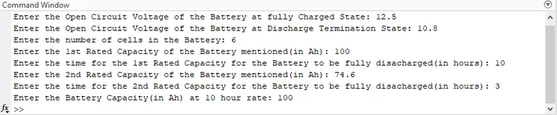
Inputs given to the MATLAB Script File based on the specification data in the Datasheet of the Yangtze Solar’s 6-GFM(G)-100 Ah Gel Battery
Results on running the MATLAB Script:
Observation(s) & Conclusion(s) pertaining to Battery Voltage-Depth of Discharge (DoD) Plot:
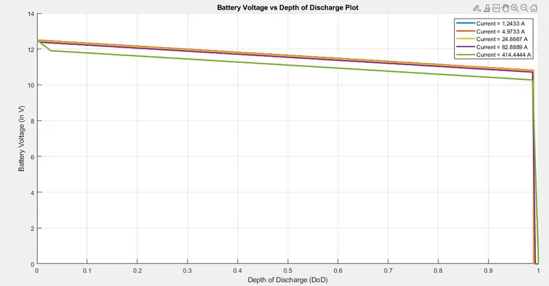
Battery Voltage vs Depth of Discharge(DoD) Plot [Normal View]
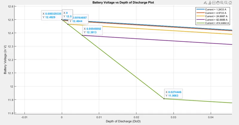
Battery Voltage vs Depth of Discharge(DoD) Plot [Zoomed View]
- On observation of the plot obtained, it can be concluded that for all currents, the battery voltage starts decreasing with a high rate and after some time, the rate at which Battery Voltage decreases lowers down significantly before again suddenly decreasing at a very high rate as it approaches a DoD (Depth of Discharge) of 99%.
- As the Discharge current increases, the DoD for which the Battery Voltage experiences an initial steep decrease (from OCV at full charged state) also increases before the slope of the Battery Voltage curve again lowers down w.r.t to the DoD. For example, for discharge current of 414.4444 Amperes, the Battery Voltage Steeply decreases from 12.5 Volts to 11.9063 Volts from DoD=0 to DoD=0.027444 before the slope again lowers down. And for discharge current of 24.8667 Amperes, the Battery Voltage steeply decreases from 12.5 Volts to 12.4644 Volts from DoD=0 to DoD=0.0016 before the slope of the curve again lowers down.
- As the Discharge current increases, the Battery Voltage-DoD characteristics shift downwards.
Observation(s) & Conclusion(s) pertaining to Battery Voltage-Time Plot:
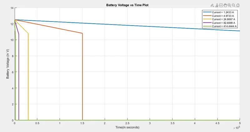
Battery Voltage vs Time Plot
- As per the plot obtained, as the discharge current increases, the time taken to discharge the Battery reduces.
- This is evident as the negative slope of the Battery Voltage w.r.t. time is steeper for higher value of current compared to lower values of current until the Depth of Discharge reaches about 99% and then there is free fall of Battery Voltage to 0.
- As per the data sheet details about the rated capacity of the battery and it’s discharge time, the discharge time for a 74.6 Ah rated Battery is 3 hours or 3 X 3600 seconds = 10,800 seconds. But according to the plot obtained, the 74.6 Ah battery (corresponding to the discharge current of 24.8667 Amperes), the discharge time obtained is roughly about 29300-30100 seconds.
- Since the mathematical Battery Model implemented is based on Empirical model comprising of Empirical formulas (Peukert’s Equation,OCV-DoD Equation,etc) and is compared with a Practical Lead-Acid Battery parameters & specifications, there are many assumptions & things not taken into consideration while implementing the empirical model which are applicable for a practical Battery. For example, the temperature effects on the Battery has not been considered for the Empirical Model, the internal resistance remains constant in the Empirical Model which is not true for a practical model, Float Voltage has not been considered in the empirical model while the effect of Float Voltage has been taken into consideration in the practical model, etc.
- Due to many assumptions for this empirical model and many parameters and their effects on the Battery not taken into consideration, there is significant difference seen in the Discharge time of the Practical Battery and Discharge Time of the Empirical Model of the Battery for the same Rated Capacity, Discharge Start Voltage and Discharge Termination Voltage.
Observation(s) & Conclusion(s) pertaining to Battery Voltage-Charge Removed (CR) Plot:
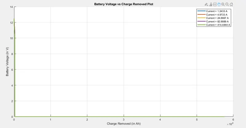
Battery Voltage vs Charge Removed(CR) Plot [Normal View]
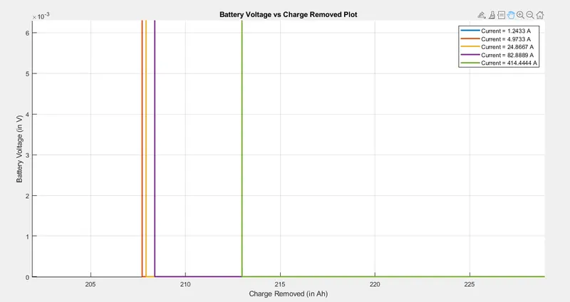
Battery Voltage vs Charge Removed(CR) Plot [Zoomed View]
- As expected, the higher the current for discharging the Battery, more the charge removed from the battery or more the capacity of the Battery decreases.
Observation(s) & Conclusion(s) pertaining to Battery Voltage-Charge Supplied (CS) Plot:
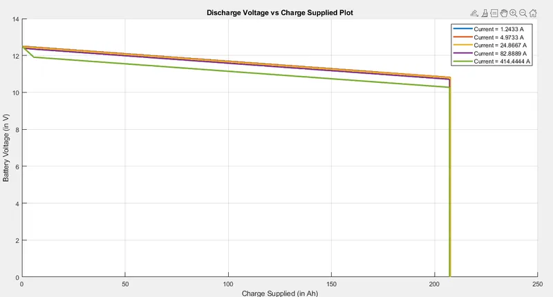
Battery Voltage vs Charge Supplied Plot [Normal View]
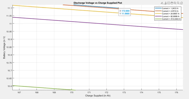
Battery Voltage vs Charge Supplied Plot [Zoom View 1]
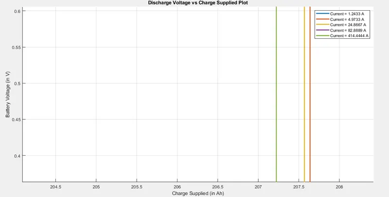
Battery Voltage vs Charge Supplied Plot [Zoom View 2]
- The Characteristics of this plot is similar to the Battery Voltage-DoD Curve. As seen from the plot, the least charge is supplied to the Battery operating at higher current.
- At termination state, higher the current at which Battery is operating, lesser the charge supplied to the Battery at that current.
- The Battery operating with the least amount of current for this objective (I=1.2433 Amperes) terminates supplying charge at a Voltage Level of 11.0988 Volts while the Battery operating at other current values terminates operating a Battery Voltage of 0 Volts.
On basis of the the plots obtained, it can be conculded that, as the discharge rate increases, the available capacity of the Battery decreases and hence lower the delivered capacity.
REFERENCES:
- https://www.victronenergy.com/media/pg/SmartShunt/en/battery-capacity-and-peukert-exponent.html
- Electrical Vehicle Technology Explained, 2nd Edition by James Larminie & John Lowry
- https://www.mdpi.com/2313-0105/5/3/58/htm
- https://www.sciencedirect.com/topics/engineering/peukert-equation