Making a washing machine model and a gear transmission model in Simulink using control logic.
AIM:
To apply the state control logic for making the simulation for washing machine and gear shifting login.
OBJECTIVES:
- To set a control logic system of a washing machine for the set time sequence and process.
- The speed is variable for the gear shifting logic and to make a control logic for the shifting of the gear according to the speed.
GENERATING A SIMULINK MODEL FOR A WASHING MACHINE FOR DIFFERENT STAGES.
The washing machine is a device that is basically used for cleaning clothes. There are various operations that the machine needs to perform for cleaning the clothes. All these operations are actually time-dependent, and for each operation, there is a set time for the start and the finish.
Operation performed
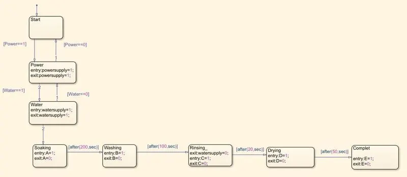
- Soaking - 200 sec (0-200sec)
- Washing - 100 sec (200-300sec)
- Rinsing - 20 sec (300-320sec)
- Drying - 50 (320 -370 sec)
- complete (>370 sec)
Blocks Used:
- Constant - Power and water supply.
- Toggle switch - determining whether the power and water supply ON or OFF.
- Lamp - Indicator of the opt[ut signal
- state flow - Control logic
- Display- To display the output of the operations.
SIMULINK MODEL
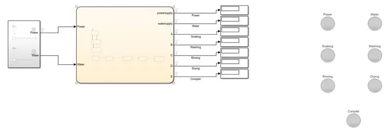
Main System
Subsystem
Stateflow Model
Explanation
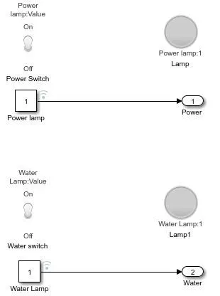
- The power and the water supply for the system are given from the subsystem unit which has the coordination of 1 and 0 for the ON and off conditions.
- The toggle switch is used to control the output and the lamp is used to indicate the required out for the system.
- These signals are given the Stateflow model, as the signal is 1 and 0 the system will run only if both the inputs are 1 if any of the inputs is 0 the system won't run.
- The power and the water are going to start the system the first stage will be soaking for 200 seconds, the power and the water will be ON.
- As this process ends the next process will be washing which will last for 100 seconds that will last for a total of 300 seconds.
- The next process will be rinsing which is a small process of 20 seconds, here the water will stop as we don't need the water flow henceforth the total time will be 320 seconds.
- The final step in the process will be drying this will last for 50 seconds and after the time stops the process will be completed, the final stage will be >370 seconds.
- As the process goes on the lamp will be indicating the Stateflow inside the system.
CONDITION I Both the water and power are ON
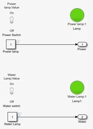
Both the water and the power are ON after the washing machine logic is activated.
SOAKING
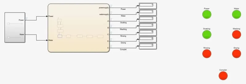
The water and the power will be turned ON and the system will start, the first process of soaking will be initiated. The process is for 200 seconds, the power water and the soaking lamp will be ON throughout the process.
WASHING
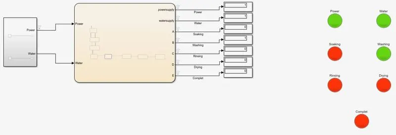
The second stage in the process is washing which is a 100 seconds long process. During this process, the water and power will be ON. The soaking lamp will be OFF and the washing Lamp will be turned ON. The total process up till now will be of 300 seconds.
RINSING
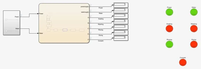
The rinsing process will be initiated after 300 seconds and will last for the next 20 seconds. The Power water and the rinsing lamp will be On for the total process. The total cycle timing till now is 320 seconds.
DRYING
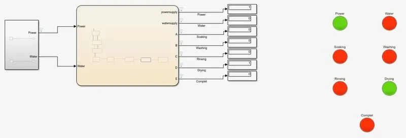
After 320 seconds the drying process will start and then it will continue till 370 seconds. During the drying process, the water will be OFF as we don't need water for drying.
COMPLETED
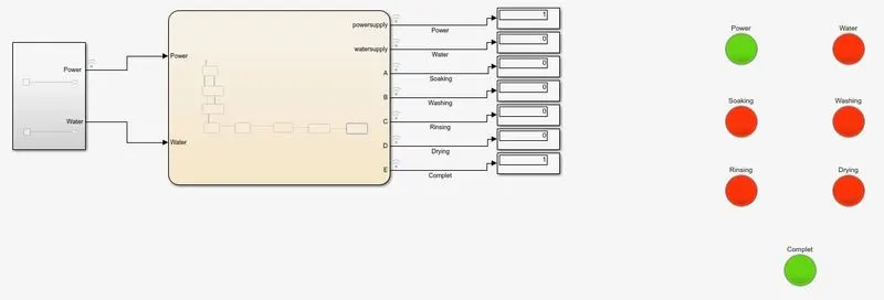
The final process will end after the time cross 370 seconds. After all the process are completed the machine will no longer take water and power unsell and until the user unloads the machine and set up a new load.
CONDITION II Water supply for the system is OFF
Here we will be turning the water supply for the system OFF.
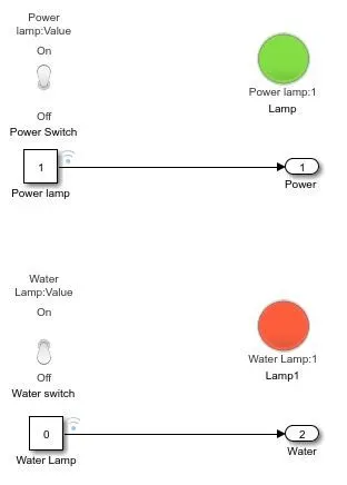
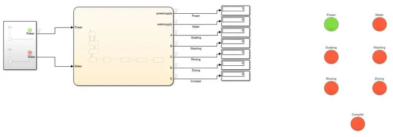
As we can see when the water is turned OFF the system doesn't run further and stops turning the power ON. All the further processes hence further won't get executed because all the process needs water for their working that is not getting supply.
CONDITION III When power and water both are OFF
In this condition, we will be turning the main supply and water both OFF.
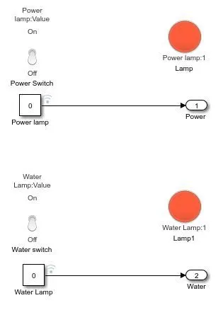
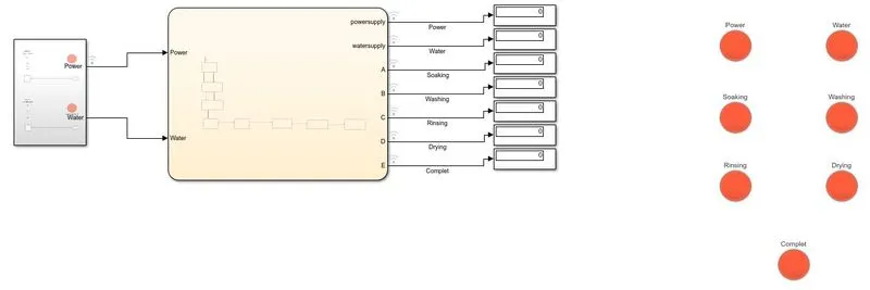
As expected the complete machine is turned OFF. No process gives any output for the system as the two basic supply inputs are not being provided.
RESULT
The washing machine ran successfully and all the operations were completed in the proper sequence and the set time by the user.
GENERATING A SIMULINK MODEL FOR GEAR SHIFTING MECHANISM ACCORDING TO SPEED INPUT
The simulation that we are trying to run here is an automatic gear transmission system that shifted gear according to the changes in the speed of the vehicle. This system uses a completely different mechanism for the shifting of the gears.
Speed control for different gears
- 1st gear (0-15 kmph)
- 2nd gear (16-25 kmph)
- 3rd gear (26-40 kmph)
- 4th gear (41-60 kmph)
- 5th gear(>60 kmph)
Block Used for the simulation
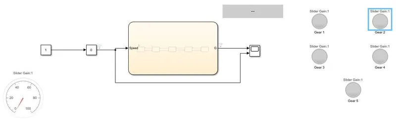
- constant block - Input for the slider gain
- Slider gain - to vary the speed
- State flow - Control logic
- Scope - to record the output
- lamp - gear indication.
- Display - to show gear number.
- Gauge - To show the speed value.
SIMULINK MODEL
Main model
Chart
EXPLANATION:
- At the beginning the slider will be at zero position, there will be no indication in any of the sensors.
- Once we increase the speed of the vehicle, the output will be given to the slider-gain and from there to the control logic system. Based on the speed input the gear will be shifted accordingly.
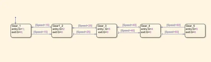
- When the speed is between 0-15 kmph the 1st gear will be executed.
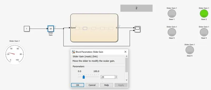
- When the speed is between 16-25 kmph the 2nd gear will be executed.
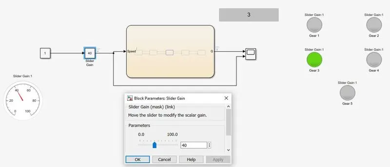
- When the speed is between 25-40 kmph the 3rd gear will be executed.
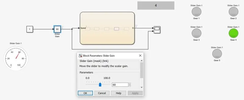
- When the speed is between 41-60 kmph the 4th gear will be executed.
- When the speed is between 60-100 kmph the 5th gear will be executed.
- The variation of the speed can be seen in the speedometer set in the system.
RESULTS
1st gear (0-15 kmph)
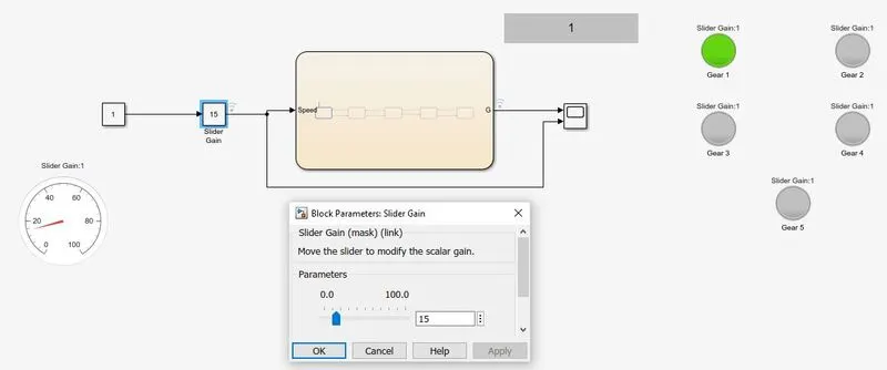
2nd gear (16-25 kmph)
3rd gear (25-40 kmph)
4th gear (40 - 60 kmph)
5th gear (> 60 kmph)
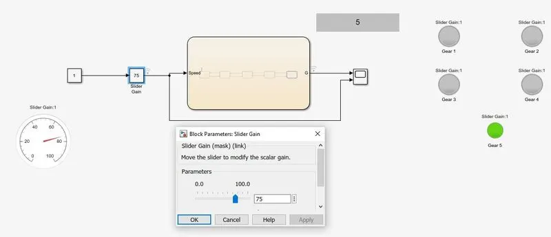
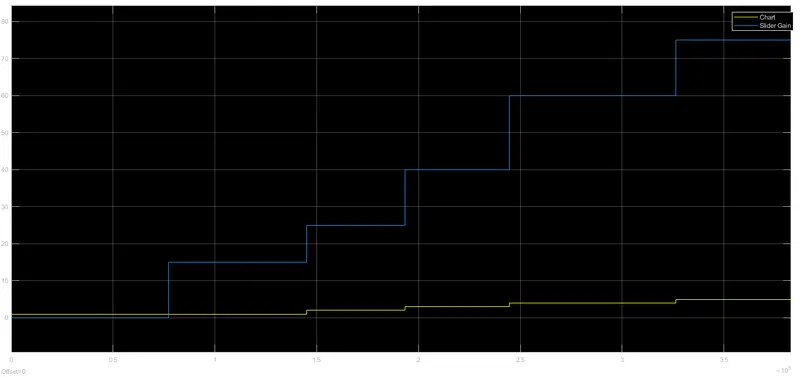
As we can see all the gear were activated according to the throttle speed and all the conditions for the speed control are satisfied.
The output for the scope of the system is shown below this plot is for the speed VS gear shift
CONCLUSION
Both the simulations for the washing machine and gear transmission are made properly and were executed accordiding to the given input and conditions.