Introduction to REVIT concepts
1) From the file menu, create a new project (Structural / Architectural / Construction template ) and name the project appropriately
AIM:
TO create a New Revit Project.
INTRO: Creating the new Revit project by using the file menu and creating the various templates for working on different disciplines like Architectural, Structural, Construction, Mechanical.
PROCEDURE:
Open the Revit software on the desktop,
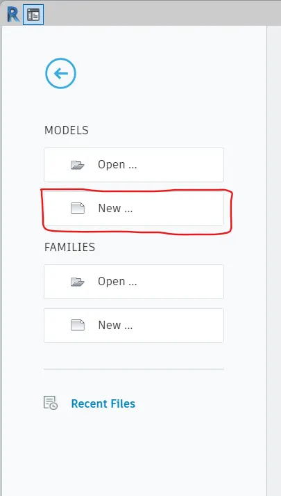
After opening the Revit choose the New option on the Home tab for creating the New Revit project.
Creating the New Project Templates:
Click the Browse option for Browsing the different Templates and select the required template.
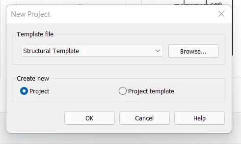
Structural Template:
The structural template is used for creating the structure of the building like Beams, Columns, Slabs, Loads, etc., of the project, and its analysis loads of the structure.
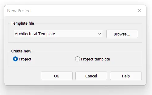
Architectural Template:
An architectural template is used for creating the Architectural elements of the project like Plan, Elevation, and sectional views, and other overviews of the building or structure.
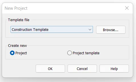
Construction Template:
Construction templates combine all the other disciplines and put forward a template that lets us present our project with a focus more upon construction rather than the design aspects of it.
In the construction template, a schedule sheet will be automatically created by Revit in Construction Template.
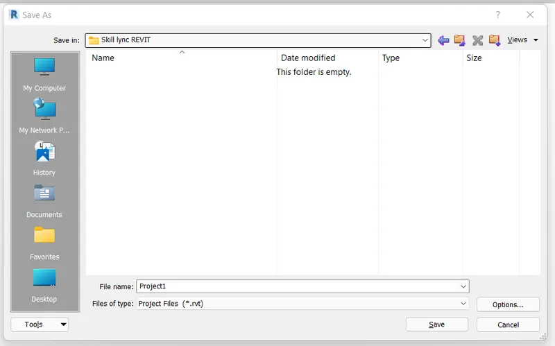
Select any one template from that for working on the project, and SAVE the project and name the project.
like as shown given below.
RESULT:
Created the New project file with different templates for working on the project and saved it.
2) Save the new project file. Close and open using icons from the file toolbar
AIM:
Save the new project file. Close and open using icons from the file toolbar
PROCEDURE:
Creating the New project with Architectural Template then saved the project.
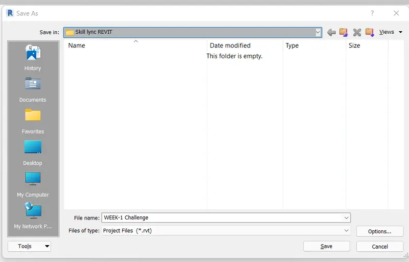
Save the new project file by selecting the File tab
Choose the save option
choose the storage path
Named the project with an appropriate name
Click the save option.
Closing the project:
For closing the software click the "x" mark on the top right corner
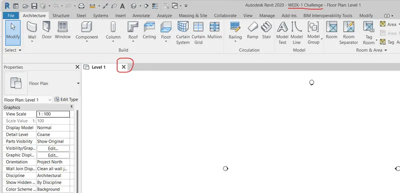
For closing the Project the click the "X" mark on the top of the Revit working area.
Opening the project.
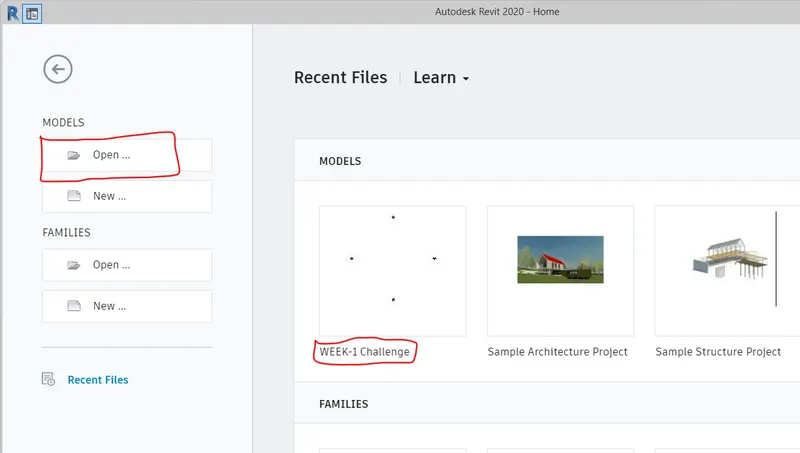
After closing the project file, reopen the file by clicking the OPEN option in the Home tab and choosing the appropriate project file to open, then click the open option.
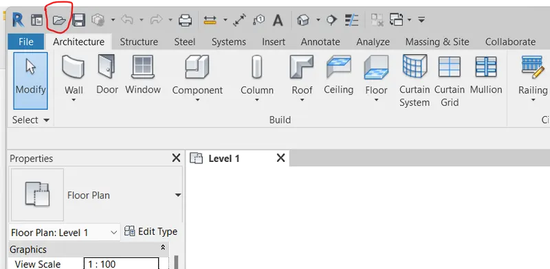
Opening, the project by clicking the Icon as I marked at the top of the ribbon, and choosing the respective project file to open, then click the Open option.
RESULT:
Saved the Created file by using the file tabs, then close the project then Re-open the project by choosing the Icons in the File tab.
3) From the architecture/ structure toolbar familiarize yourself with options to draw a wall. Create a rectangular layout of walls of about 40’-0” X 35’-0”
AIM:
To create a rectangular layout of walls of about 40’-0” X 35’-0”
INTRO: Creating the layout by using the wall tool invoking from the Architectural/Structural toolbars and taking the given dimension of the layout.
PROCEDURE:
Select the Level to start the layout
Level-1 is defined as the Datum or Reference line.
Level-2 is defined as Additional levels.
Select Level-1 to start the layout from the datum line.
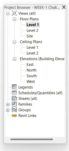
After selecting the Levels
Click on the Architecture Tool tab
Click on the wall tool.
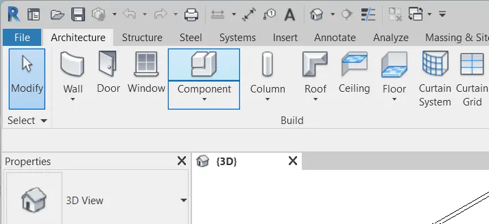
select the line tool option in the draw tab then
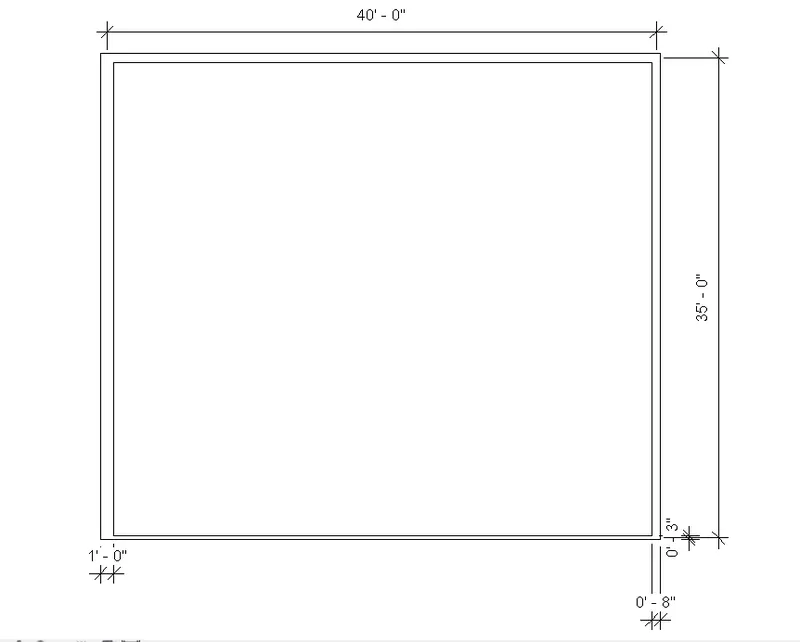
Draw the layout as per given dimensions 40' in horizontal and 35' in vertical,
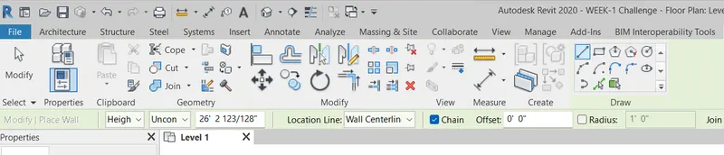
RESULT:
Sketch out the layout as per the given dimensions.
4) From the Annotate toolbar use the aligned option to add dimensions to the layout
AIM:
Dimensioning the layout by using the Annotate Toolbar.
PROCEDURE:
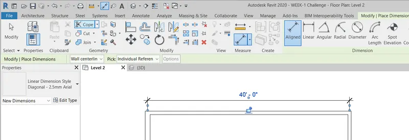
Select the Annotate File Tab for dimensioning the layout
select the Aligned or Linear option to plot the dimensions

Select at the center of the wall
select at another end of the wall
as shown below figure.
RESULT:
Dimension the layout by using Annotate tool tab.
5) Use the properties browser to switch to different wall types
AIM:
Use the properties browser to switch to different wall types
INTRO:
Properties Browser helps to Edit the Structure or Object like Walls types, location, levels, structural elements, Dimensions, etc.,
PROCEDURE:
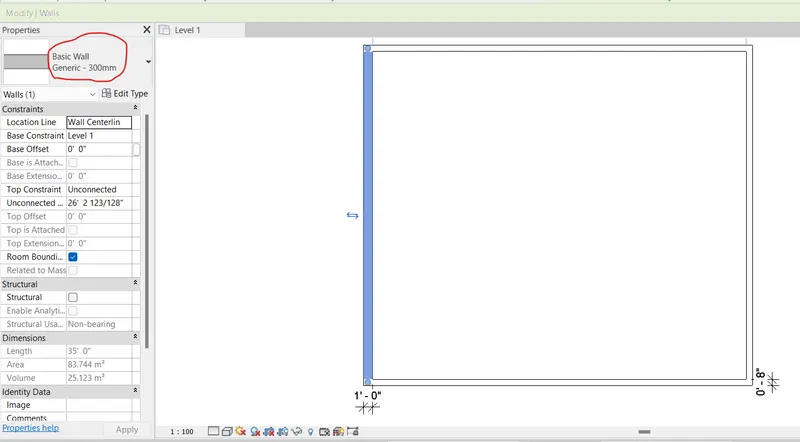
select the wall to change properties
Select basic wall option
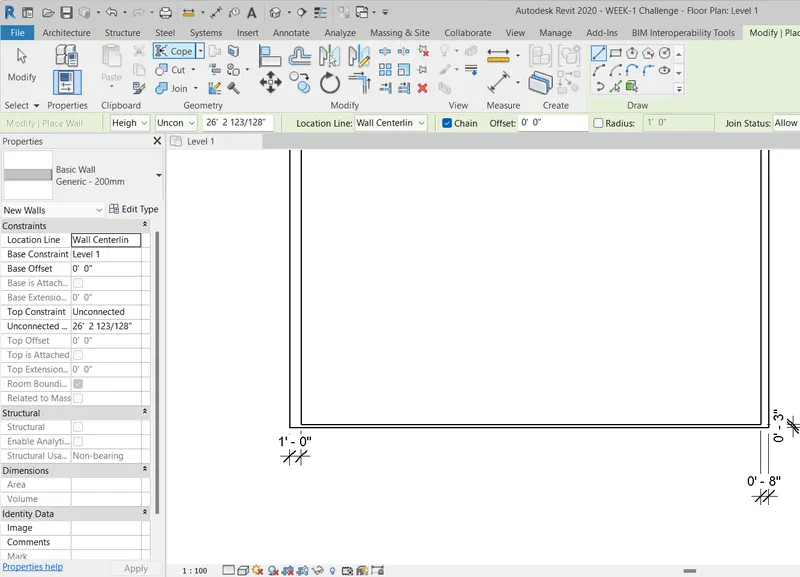
choose the wall type as per requirements dimension and wall type.
similarly to other required walls for changing.
RESULT:
Wall type changed by invoking the Properties.
6) Create a 3D view from the view toolbar and save the view with the appropriate name
AIM:
Create a 3D view of the layout and save it with the Appropriate name.
PROCEDURE:
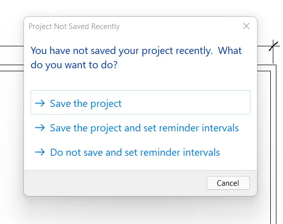
creating the 3D view select the view file Tab
select 3D view in tools and
select default 3D view
select Save the project option>

RESULT:
Created 3D view by using the various tools.
7) Navigate through the 3D model using the view cube. Orbit/pan through the model layout created
AIM:
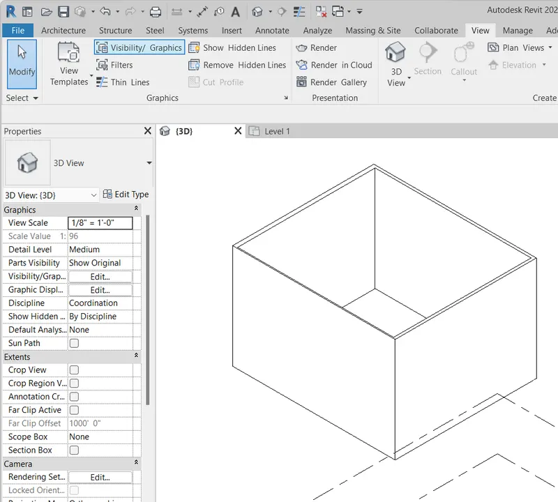
Navigate through the 3D model using the view cube. Orbit/pan through the model layout created
INTRO:
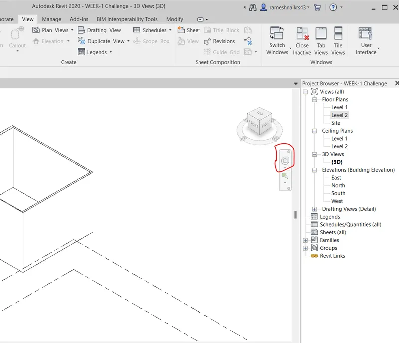
The navigation wheel provides access to general & specialized 3D navigation tools.
PROCEDURE:
Click a wedge,
hold & drag to platform a specific navigation action.
Release the mouse button to restore the steering wheel.
ORBIT: It is used to orbit or move the object in all directions.
ZOOM: increasing the object size by zooming in and decreasing the object size by zooming out.
PAN: It is used for moving the views.
REWIND: It revises all navigation modes have we done previously.
WALK: Moving the object in and out
UP & DOWN: Moving up& down
CENTER: Set the zooming/orbit at the center of the object.
LOCK: Lock the current position of the object. move by using the arrow keys
RESULT:
Navigate the object by using the Navigation wheel.
8) Use the visibility settings option below to switch model to shaded, realistic, hidden lines options
AIM:
Use the visibility settings option below to switch models to shaded, realistic, hidden lines options
PROCEDURE:
Changing the visibility style
Select the Visibility style Icon
Visibility Options are displayed
select the required visibility options
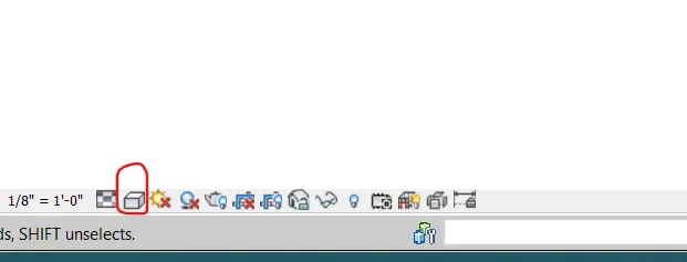
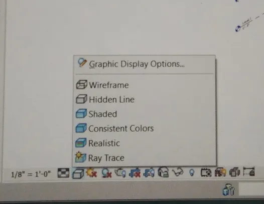
Visual style Icon Visual style options
Select the Realistic option for showing the object in Realistics mode
Similar to other visual styles.
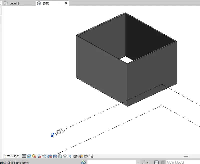
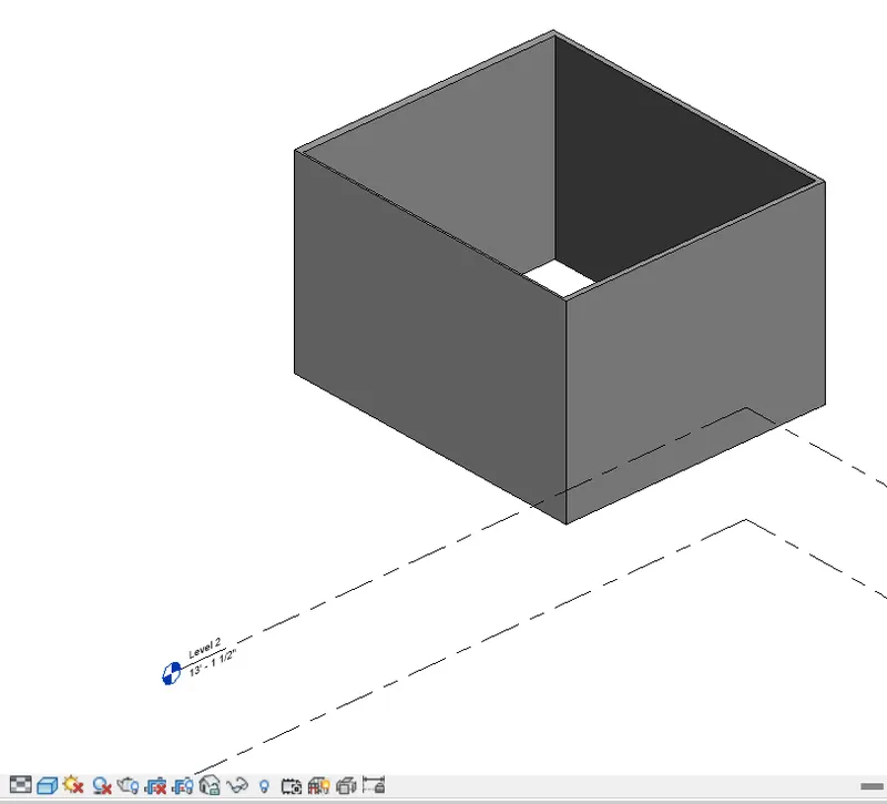
REALISTIC VIEW SHADED VIEW
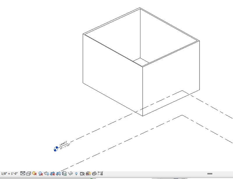
HIDDEN LINES VIEW
RESULT:
Created the Visual style by using the Visibility style Icon.
9) Turn the sun path on and off to view shadings in the layout created
AIM:
Turn the sun path on and off to view shadings in the layout created
PROCEDURE:
Sun path is used for knowing the geological features of the building like sunrise and sunset, and it shows the visual representation of the sun's range of movement across the sky.
Invoking the Sun path on/off
Click the sun icon at bottom of the ribbon in Revit
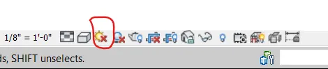
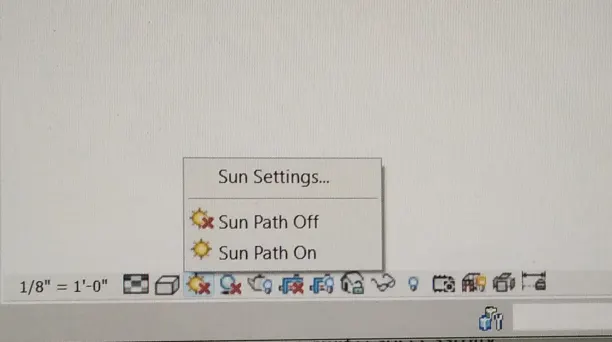
Sun path Icon Sun path On/Off options
Select the sun path On option
sun path will create like as shown below figures.
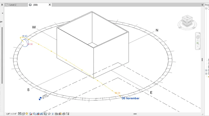
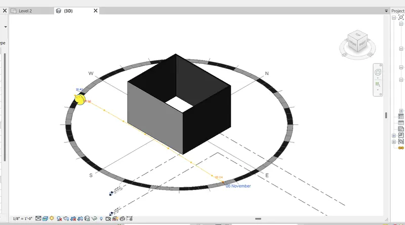
SUN PATH ON IN HIDDEN VIEW SUN PATH ON IN REALISTIC VIEW
RESULT:
Turn-ON/OFF the sun path by using the Sun path Icon.
10) Use the Manage toolbar to enter project settings, project name, and project issue date (choose according to your convenience).
AIM:
Use the Manage toolbar to enter project settings, project name, and project issue date
INTRO:
The project settings help the project customization, including project information, project name, address, Stauss, line style, Identity data, Organization name, description.
PROCEDURE:
Invoking the Project information tool
Select the Manage File tab
select the project information in the Project setting

Specific basic information about the project, including the project status, and clint information.
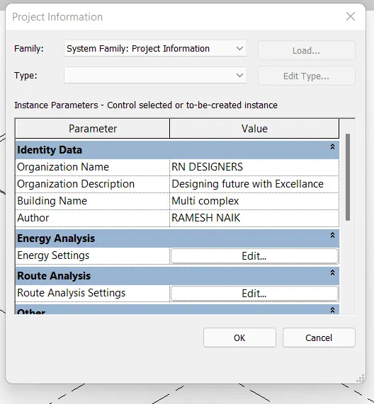
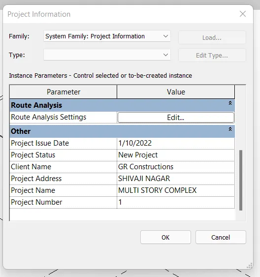
Identity Data Project Data

Project Address
RESULT:
Specify the project information by invoking the project setting in the MANAG tool tab.
11) What is the Analyze toolbar used in Revit? How it is beneficial for design and modeling
It helps in creating Revit models, these toolbars consist of many other options which help in load combination, boundary conditions, load, and support system are one among the tool under this Analyze toolbar wherein we get to adjust the model and add additional support to the present model. It also verifies the analytical & physical model for consistency.
space separation, space naming space tagging is also the option available assigning the names and numbers the architectural rooms.
12) What are the links that Revit supports to be linked to the model?
LINK REVIT: Link one Revit model to the other or the current Revit project
LINK CAD: Link CAD file to the present Revit project
LINK IFC: Link an IFC file to the current project for the information that is required for additional design work
LINC TOPOGRAPHY: It links the existing Topography to the present Revit model
LINK IMAGE: It allows us to link an image for the progressing Revit model
MANAGE LINKS: It manages the links such as CAD, markup the DWF files & all the BIM works that are related to the present file.
LINK PDF: It allows us to link an image for the progressing Revit model
COORDINATION MODEL: It links up an NWD or NWC file to extract content for the Revit model.
DWF MARKUP: It links the marks up DWF files into the present Revit project so that we can see markups in the corresponding sheets.
POINT CLOUD: It links a point could file to the current Revit project.
13) Why do you need the Collaborate tab in Revit? How it supports modeling and its efficiency
Revit need to collaborate with other disciplines because
- It keeps all parties updated with the current project
- It allows key design features to be communicated effectively via visual templates and color fills.
- It allows users to divide the model into work sets, which can be made editable or not editable by the current user to avoid confusion and lessen computing load.
- It allows users to define parameters as the design progresses, to make model-wide changes quick and easy.