Introduction to REVIT concepts
- Revit is a 3D parametric modeling software package for building information modeling (BIM).
- Revit is a building information modeling software used across many profession such has architects, structural engineers, designers, and contractors.
- Concept of autodesk about revit is combination of coordination and computation.
- Coordination means operation between multiple display.for example, a architecurtal resdiential building can be used or linked for operation for electrical,plumbing,structursl etc.,
- Computataion means a new concept of energy calculation,material or quantity schedules,load analysis etc.,
- Working with revir has more benifit compared to 2D CAD tool.
- Real time modeling-main advantage of revit.
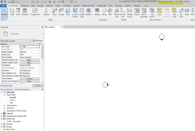
1)AIM: Creating a new architecural project from file menu and name the project with residential building.
INTRODUCTION: File menu is the panel here a file can created,opened,saved,print or export/import.
It holds of different category of project such as architecural project/project template,strcutural project,construction project,mechanical project,electrical project and plumbing project.
PROCEDURE:
- Open revit 2022 file from start window.
- left side of the screen,display open,new project.
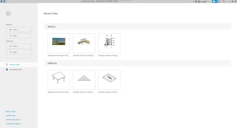
- click on the new,oprtion browser option.
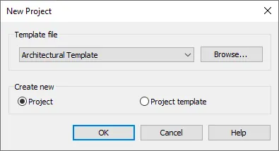
- select architecural from template file.
- click on OK.
- in order to name the file,once the architecural template open.
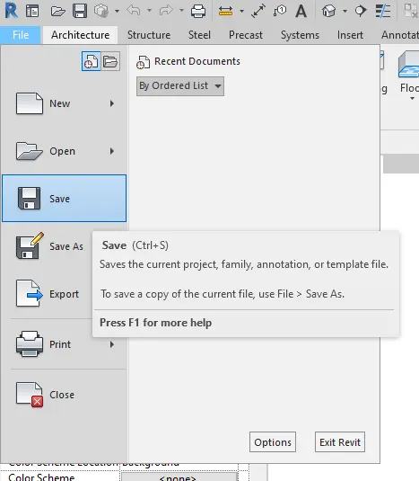
- click on file menu,click on save option.
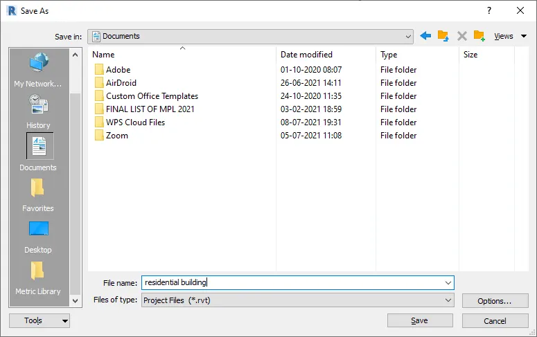
- save the file with name residential building.
RESULT:
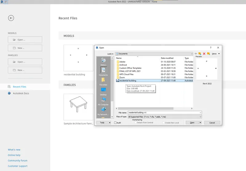
2)AIM: Save the new architecural project file and open the file from file again.
INTRODUCTION: File menu is the panel here a file can created,opened,saved,print or export/import.
It holds of different category of project such as architecural project/project template,strcutural project,construction project,mechanical project,electrical project and plumbing project.
PROCEDURE:
-
- click on file menu,click on save option.
- save the file with name residential building.
- Close the revit app,reopen.
- select open oprtion from left side of the screen.
- search residential building(saved file),click open.
RESULT:
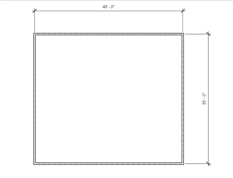
3) AIM: To draw a layout of wall dimension 40'x 35' using architecural toolbar.
INTRDOCTION: walls are instances of predefined system family types, which represent standard varieties of wall function, composition, and thickness. It is with two option architecural wall and strcutural wall.
PROCEDURE:
- open the revit file.
- from previous saved archeticural building named file.
- for architecural to be in impherical units.
- go to file menu-select option.
- click on the file location.
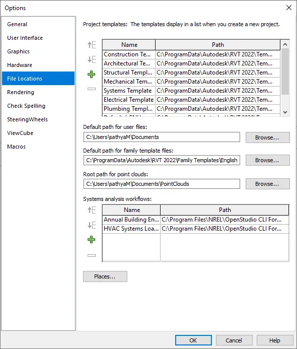
- click on + symbol to add the template.
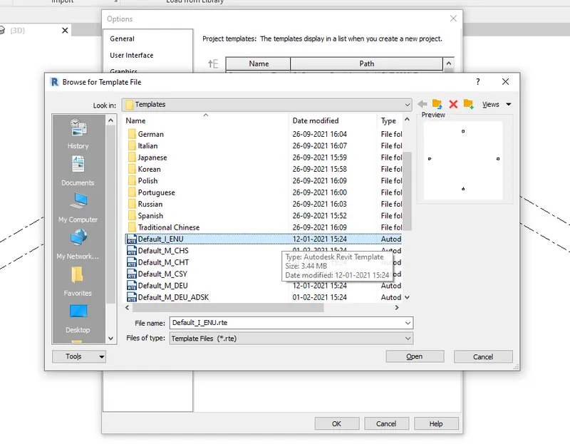
- once it is clicked,computer file menu opens-select window c.
- then RVT 2022-select template.
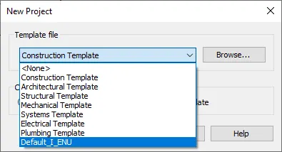
- from template option displyed-select DEFAULT_I_ENG.
- again go back to file menu,select new and select default_i_eng.
- select architecural wall.
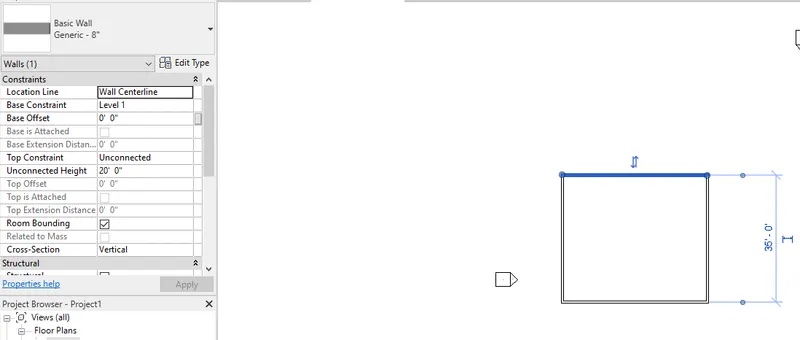
- select basic concrete 8" width type wall.
- select line command,enter first value as 40' towards right.
- 35' towards down and 40' towards right and connect the first point.
RESULT:
4) AIM: Measuring the above created layout using aligned option from annotate tollabar.
INTRODUCTION: annotation means adding notes(text/measure)giving a explanation.
In revit annotate toolbar consist mainly of :
- dimension measure such as alinged,linear,diamter,angle etc.
- text command
- tag command-room,ovreall or for defined unit.
PROCEDURE:
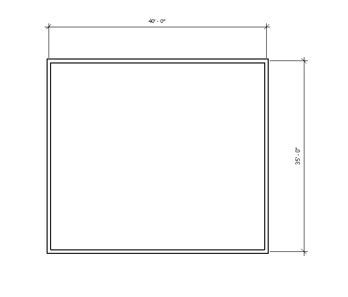
- for previous rectangular wall layout,go yo annotate tollbar.
- select aligned from annotate toolbar.

- place cursor on one end of wall and click on another end of wall.
- repeat the same for another side of the layout also.
RESULT:
5) AIM: using properties browser to switch from concrete 8" to concrete 6" wall of recatngular layout.
INTRDOCTION: properties browser is displayed on left top corner on the screen or can be set from maneger toolbar. It display the property of the selected unit,for example if we select wall,it display its type and thickness.
PROCEDURE:
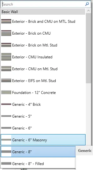
- select one side wall from rectangular layout.
- once u select,properties bar display type of wall.
- click on properties and changle the wall to concrete 6" from family of walls.
RESULT:
6) AIM: creating 3d view from view toolbar and save the 3d view using view maneger.
INTRDOCUTION: view toolbar is mainly used for setting visibility graphics,show 3dview elevation view and also to make duplictae/tile view.
PROCEDURE:
- after drafting the layout.
- click on view toolbar.
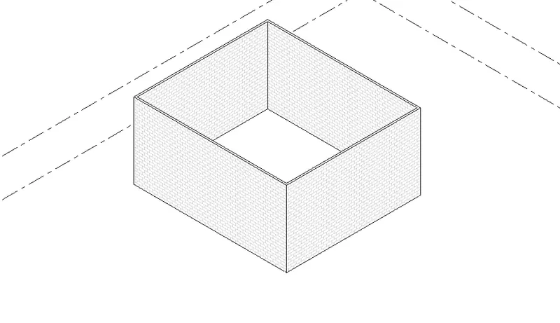
- click on 3D view icon,display the 3d view of the layout.
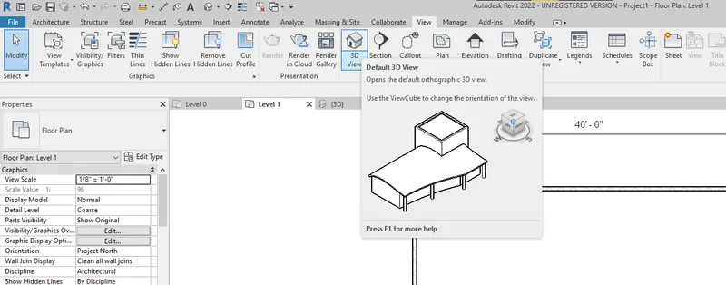
- once the view is set,rename the current view as 3d-wall.
RESULT:
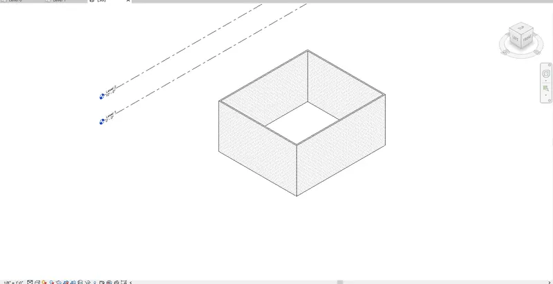
7) AIM: Navigate through the 3D model using the view cube. Orbit/pan through the model layout created
INTRDOCUTION: view cube is used for navigating the wall in all dierction inclusing 2d view and 3d view. Pan is used to drag the view or set the view as per requirement.
PROCEDURE:
- for previoys layout,go to view toolbar.
- select 3d view/select saved view from left project browser option.
- use the view cube to set SW isometric view .
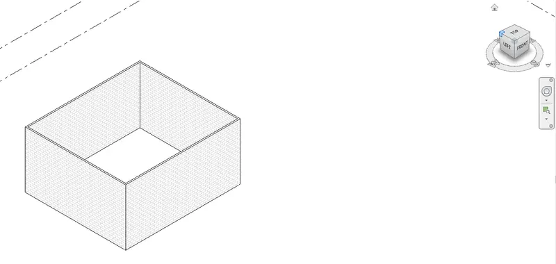
- from navigation toolbar,select pan and set the model to the center.
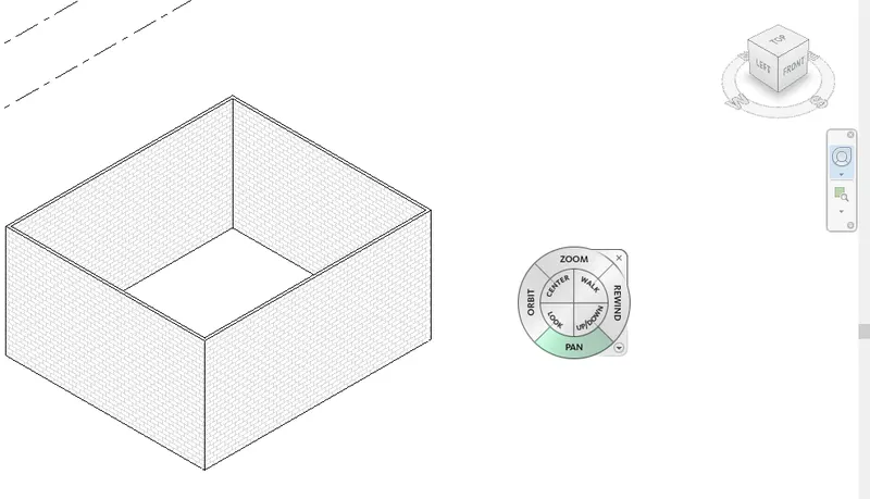
- save the view as 3d-wall 2.
RESULT:
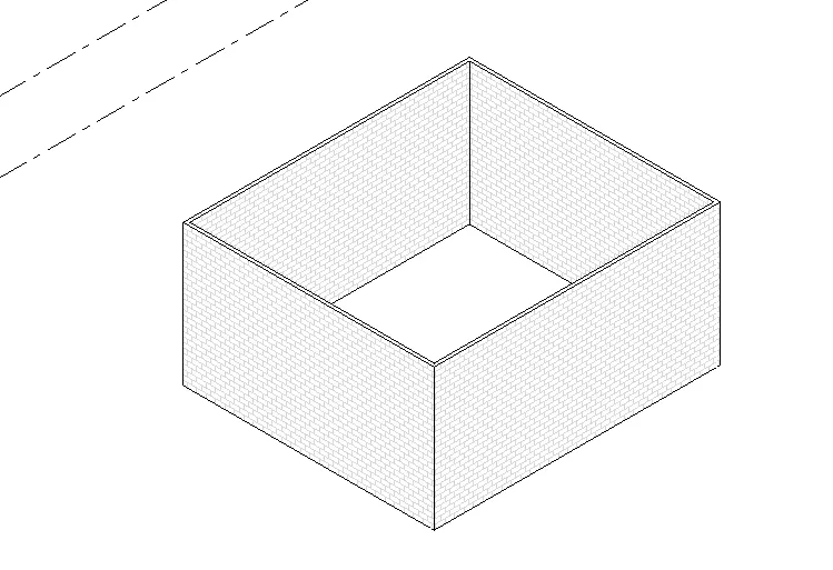
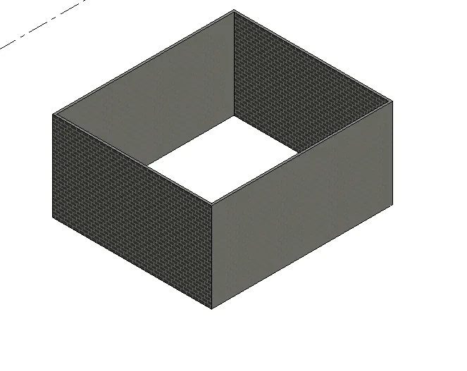
8) AIM: Using the visibility settings option below to switch model from wireframe to shaded, realistic and hidden lines options.
INTRODUCTION: visibilty setting can be done using visual style icon present in bottom of revit screen. It disply the graphic option such as hidden,shaded.realistic etc. By deafult the modeling is done in wireframe option.
PROCEDURE:
- present layout option is in wireframe.
- go to view toolbar and click on 3d view.
- got o visule style icon present in the bottom,click on the icon.
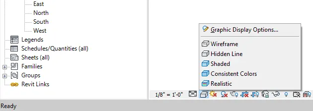
- its disply various graphic option,select shaded option and it display the alyout in that graphic.
- simiallry for hidden and realistic.realistic gives a clear view/differnce from other after applying the material to the wall.
RESULT:
realistic view
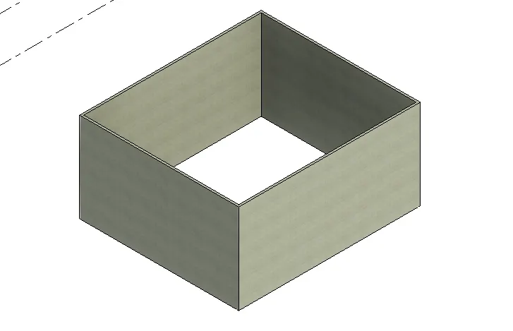
hidden view
shaded view
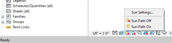
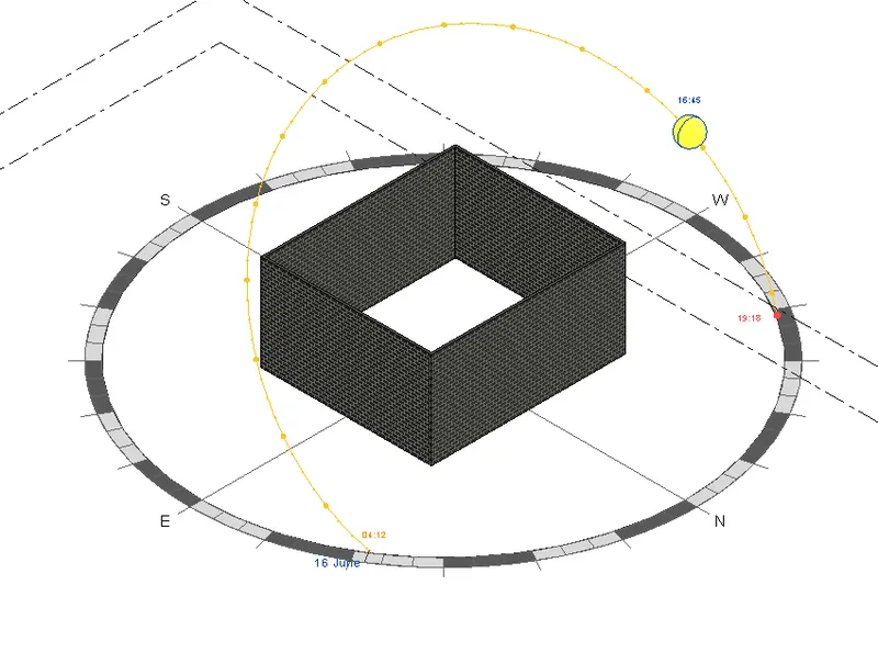
9)AIM: Turn the sun path on and off to view shadings in the layout created.
INTRODUCTION: The sun path is a visual representation of the sun's range of movement across the sky at the geographic location specified for the project.It displays in the context of the project and allows you to position the sun at any point within its range of movement, between sunrise and sunset, throughout the year.
PROCEDURE:
- once the layout is created.
- click on the sun path icon next to visule style.
- select sun path on to display the effect of it.
RESULT:
with specified setting:
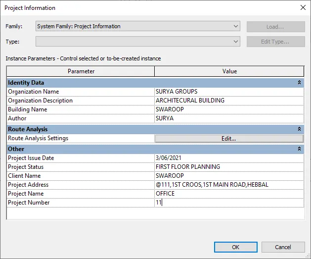
10)AIM: Using the Manage toolbar to enter project settings, project name, and project issue date.
INTRODUCTION: Project information give brief idea about details of construction company,site adress,issued date etc.,
PROCEDURE:
- go to manage toolbar.
- click on project information.
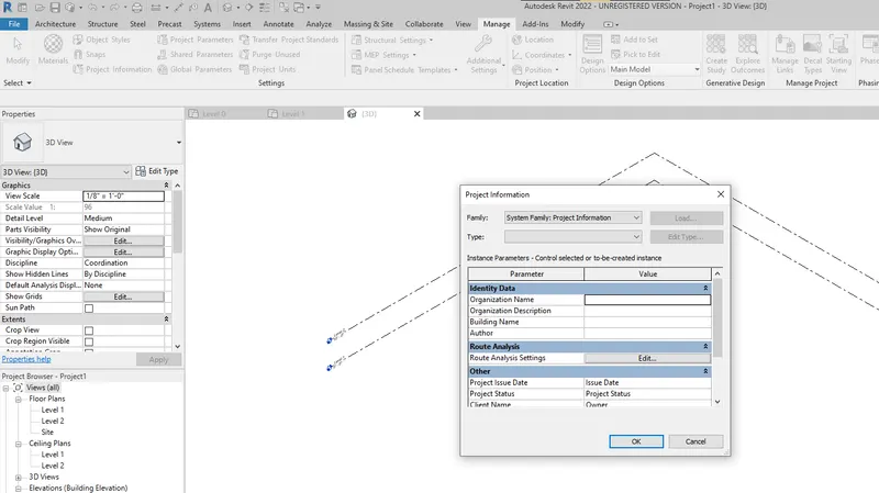
- enter the details asked in the display.
- click ok.
RESULT:
11) AIM: To know what is analyze toolbar used in revit and its benefical for design and modelling.

Analyze toolbar is used to perform annalysis mainly for structural building and also for MEP.
- It mainly consist of load condition,cases and its combination.
- Also we can define boundary condition for loading.
- Space seperator are mainly used for making space fro fiiting coller/heater equipments,
- Report ans schedules can be made from analyses such as sceduling the quantity to be used or panel schedule etc.,
- For plumbing construction,checking duct lines,pipes and system can be done.
- Main advantage of this analyze toolbar is we can create energy model of the building and analyze them,also prescribe the loaction for easy way of energy analyzes.
- Also energy modeling can be optimized with the help of graph.
12) AIM: list of the links that Revit supports to be linked to the model.

- for link,go to insert toolbar.
- LINK REVIT- it is used to link another revit model to the current revir model. for ex-if the architecural revit needed for reference to strcutural planning,model can be linked using this.
- LINK IFC-allows to link IFC(Industry Foundation Classes) to the current project for reference of its information to addtitonal design.
- LINK CAD-to link CAD file to current project.It is similar way of linking using XREf like in autocad.for example- link of a first floor plan for modeling in revit.
- LINK TOPOGRAPHY- to link current topography to the existing model. If the civil engineer has done topography detailing in other software such has civil 3D can be linked for rveit.
13) AIM:need the Collaborate tab in Revit and How it supports modeling and its efficiency.

- The main disadvenatge in autocad is ,one person has to wait to start his set for modeling untill other person completes.
- This feature is used to help all set of group to work on a single model simultaneously.
- for example- if strcutural engineer needs the architect planning for column adjustment/vice versa,can link the ongoing model.
- It allows to edit and sync a model in local area or in wide area network.
- worksharing monitor helps us to review the information about acess to the file,editing request etc.,
- when collabration needs to be done with user of not same geography or area, it can be done using revit cloud work-sharing.
- when it comes to efficiemcy- will be more than autocad as the completion of each set of modeling will be done faster way and with minimal error.