Introduction to REVIT concepts
1) From the file menu, create a new project (Structural / Architectural / Construction template ) and name the project appropriately
AIM: To create a new project and name the project appropriately.
Tools used: New project tool.
Procedure:
- open the Revit Software and Select New option.
- Further Select Which ever template Required.
- I have Selected Architexture Template.
- Save the project as Challange 1.
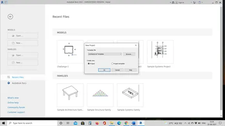
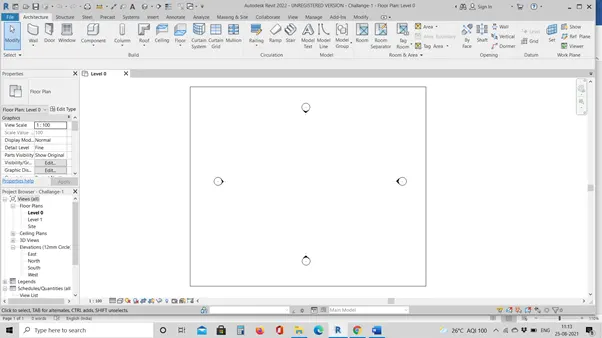
Result: The Project is Now Created and Ready for Work.
2) Save the new project file. Close and open using icons from file toolbar.
Aim: To Save new project file. Close and open using icons from file toolbar.
Tools used: Save, open and Close Tool in file menu.
Procedure:
- Click on the file menu.
- Click on the save option from the file menu and click on the option where you can save your file.
RESULT : The new project file saved.
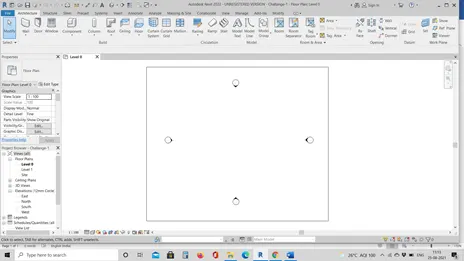
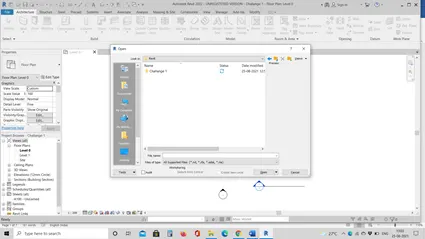
Result: The Project is Now Saved with a name Challange 1.
3) From the architecture/ structure toolbar familiarize with options to draw a wall. Create a rectangular layout of walls of about 40’-0” X 35’-0”
Aim: To Create Rectangular Wall of Size 40'x35'.
Tools used: Create wall option in Architecture menu.
Procedure:
- Create a new project and then select the template as architectural.
- Click on the wall option and specify the first point.
- Type 40’ in X direction and enter type in y direction and press enter button.
- Similarly, type in x direction to foem a rectangle layout.
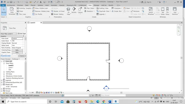
Result: The Rectangular Wall of Size 40'x35' is Created.
4) From the Annotate toolbar use the aligned option to add dimensions to the layout
Aim: To put aligned option to add dimensions to the layout.
Tools used: Alined option in annotate toolbar.
Procedure:
- select the annotate tab.
- Click on the aligned option from the annotate tab.
- Place the cursor on one end of the line and move it to other end of the line to get the dimension.
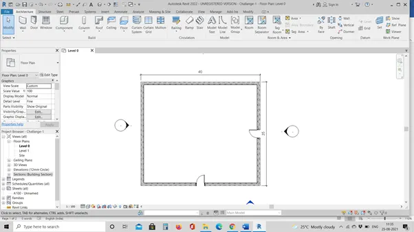
Result: The Dimension is given to the wall or layout.
5) Use the properties browser to switch to different wall types
Aim: To put the properties browser to switch to different wall types.
Tools used: Properties panel.
Procedure:
- Change the wall from 2D view to 3D view and select the wall.
- Select the desire wall from the properties which appear on the left.
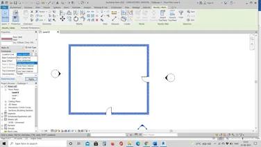
Result: The Different types of wall are discussed.
6) Create a 3D view from the view toolbar and save the view with the appropriate name
Aim: To Create a 3D view from the view toolbar.
Tools used: Default 3d view in view toobar.
Procedure:
- select the 3D view.
- By right clicking there is a option to save view
- Rename the view.
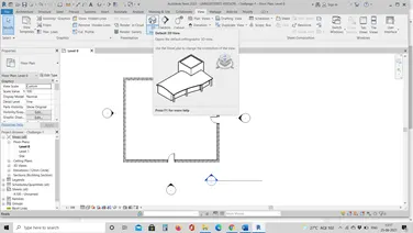
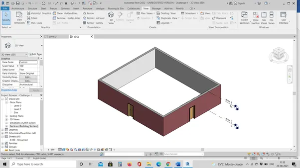
Result: The 3d view is shown and Saved.
7) Navigate through the 3D model using the view cube. Orbit/pan through the model layout created
Aim: To Navigate through the 3D model using the view cube.
Tools used: Navigate tool present at top right.
Procedure:
- select the 3D view and click on the navigation wheel which is present on the extreme right
- select the view to look in the desired direction
- move the object in any direction tosee the object in 360’ view.
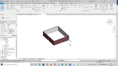
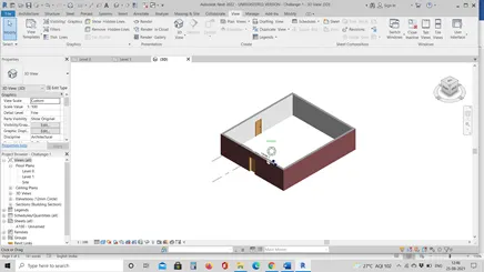
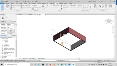
Result: The 3d model is checked in all direction using orbit tool.
8) Use the visibility settings option below to switch model to shaded, realistic, hidden lines options
Aim: To switch model to shaded, realistic, hidden lines options .
Tools used: Visual style tool at bottom left.
Procedure:
- select the 3D view
- at the extreme bottom there is an icon which is visible style click on that to get the required shade.
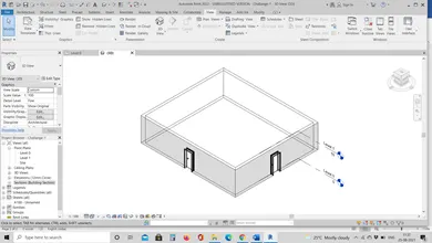
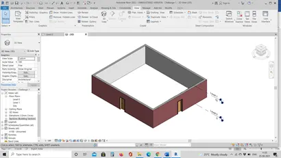
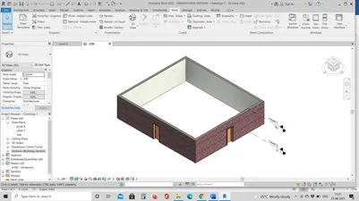
Result: The 3d model is Switched in Different models like hidden, shadded and realistic as shown above.
9) Turn the sun path on and off to view shadings in the layout created
Aim: To Turn the sun path on and off to view shadings in the layout created .
Tools used: sun path tool at bottom left.
Procedure:
- Select the manage option and select the additional settings
- Select the solar study option from the additional settings
- On the the sunpath and click ok
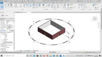
Result: The Sun path tool is used and turned off and on.
10) Use the Manage toolbar to enter project settings, project name, and project issue date (choose according to your convenience).
Aim: To Use the Manage toolbar to enter project settings, project name, and project issue date.
Tools used: Project information option in manage toolbar.
Procedure:
- click on the manage tool bar and go to the project information.
- Write the details of the project such as name and issue date etc..
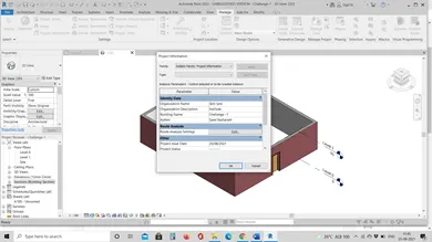
Result: The project name, date and author and place all details is saved in template.
11) What is the Analyze toolbar used in Revit? How it is beneficial for design and modeling
ANS: Analyze tool bar helps in creating revit models, this tool bar consists of many other options which help in load combinations, boundary conditions, load and cases adjustment and support systems are one amoung the tool under this analyze tool bar where in we get to adjust the model and add aditional support to the model.
Use this Quick Start workflow to perform an energy analysis based on an entire building model that is comprised of Revit building elements such as walls, roofs, and doors.
Custom zones allow you to refine the energy simulation to more closely reflect the design intent. To create a custom zone, modify the mass model, create a form to describe the desired zone, and use the Cut Geometry tool to incorporate that form into the mass model.

12) What are the links that Revit supports to be linked to the model?
ANS: Linking models is primarily intended for linking separate buildings, such as those that compose a campus. When you link a model into a project, Revit opens the linked model and keeps it in memory. The more links a project contains, the longer it can take to open.
Linked models are listed in the Revit Links branch of the Project Browser.
A Link contains the list of properties and the Sort and Filter rules. This topic references all the Ideate BIMLink tools that relates to managing Links.
Saving Link: Saving and loading Links definitions.
Loading Link: Saving and loading Links to disk.
Duplicating Link: Duplicating an existing Link.
Convert Link: Create a new Link based on an existing Link and change from Instance to Type or vice versa.
Rename Link: Renaming an existing Link.
13) Why do you need the Collaborate tab in Revit? How it supports modeling and its efficiency
ANS:
Revit provides several different ways to collaborate with team members who are also using the software. You can link multiple Revit models together, allowing team members to work in context. Through work sharing, users on the same local area network (LAN) can work together in the same Revit model
Revit provides several different ways to collaborate with team members who are also using the software.
- You can link multiple Revitmodels together, allowing team members to work in context.
- Through work sharing, users on the same local area network (LAN) can work together in the same Revit
- When collaboration needs to occur among users who are not in the same geographic location, use Revit Server or Revit Cloud Work sharing.
- Revit Server connects offices who share a network but are not in the same geographic location.
- Revit Cloud Work sharingis a cloud-based service that allows any Revit users inside or outside a network to collaborate on a Revit model.
---------------------------------------------END-----------------------------------------------