Introduction to REVIT concepts
Week 1 Challenge
1.
Aim: To create a new project (Structural / Architectural / Construction template ) and name the project appropriately
Procedure:
- Open the Revit Software
- Now select the File toolbar, from that, select New option
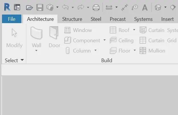
- Select the project and select New Project
- Now the Template file tab will appear, select the construction template and click ok

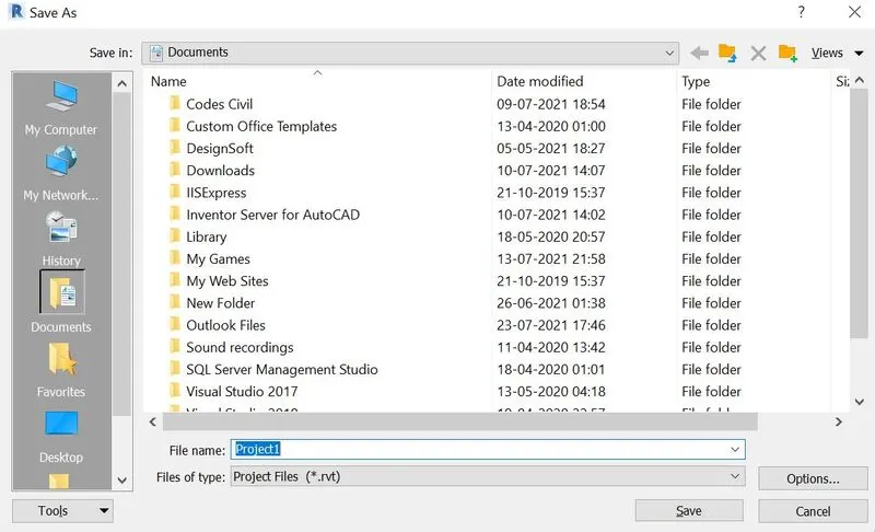
- Now open the File toolbar and click the Save as option, then select project.
- New tab will appear now, here, we can give the appropreate name for the project, lets say, "Project1" and the saving location can be chage at the top most portion of the tab appeared.
- Now if we check the title of the currect project , we can see the project name we gave on the top.

Result
A new project from the file menu is created and saved with the project name Project1.rvt
2.
Aim: Save the new project file
Procedure:
- Open the Revit software
- Now click on the Save option, now a new tab will appear
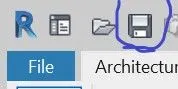
- Type the File name and Save in the desired location
- Upon checking we can see the change in file name

- Now close the software
- Again Open the Revit software
- Click on the Modify and then click Open
- Select the previously created saved file now.
- Now click the Close option from the File tool bar to close the project
Result
A new project file has been created, saved. We opened and closed the newly created file using icons from the toolbar
3.
Aim: To create a rectangular layout of walls of about 40’-0” X 35’-0”
Procedure:
- Open the Revit Software
- Now select the File toolbar, from that, select New option
- Select the project and select New Project
- Now the Template file tab will appear, select the construction template and click ok
- Now click the Architectural toolbar to create wall
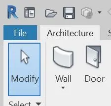
- Now select the Architecture, and select the Wall option
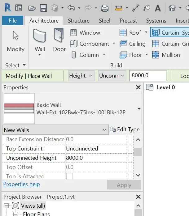
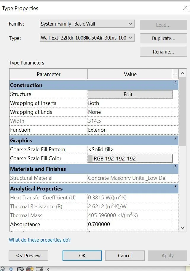
- Now upon selecting the Edit Type, a new Screen appears asking for the edit requirements.
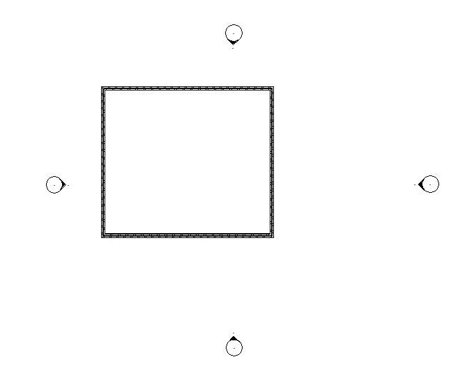
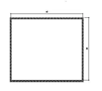
- Using the selected Wall, draw the rectangle layout of 40'0" * 35'0"
Result
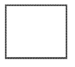
A rectangular shaped wall of 40' *35' is created
4.
Aim: To use the aligned option to add dimensions to the layout
Procedure:
- Open the Revit Software
- Now select the File toolbar, from that, select New option
- Select the project and select New Project
- Now the Template file tab will appear, select the construction template and click ok
- Now click the Architectural toolbar to create wall
- Now select the Architecture, and select the Wall option
- Now upon selecting the Edit Type, a new Screen appears asking for the edit requirements.
- Using the selected Wall, draw the rectangle layout of 40'0" * 35'0"
- Now Select the Anotate menu, and select linear dimension
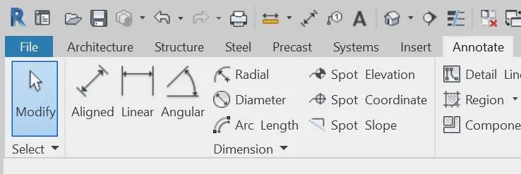
- Now using the cursor, select the starting point and ending point, to be dimensioned
Result
5.
Aim: To use the properties browser to switch to different wall types
Procedure:
- Open the Revit Software
- Now select the File toolbar, from that, select New option
- Select the project and select New Project
- Now the Template file tab will appear, select the construction template and click ok
- Now click the Architectural toolbar to create wall
- Now select the Architecture, and select the Wall option
- Now upon selecting the Edit Type, a new Screen appears asking for the edit requirements.
- Using the selected Wall, draw the rectangle layout of 40'0" * 35'0"
- Now Select the Anotate menu, and select linear dimension
- Select the default 3D view option to view in the 3D view
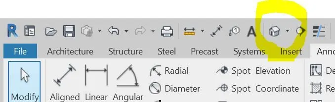
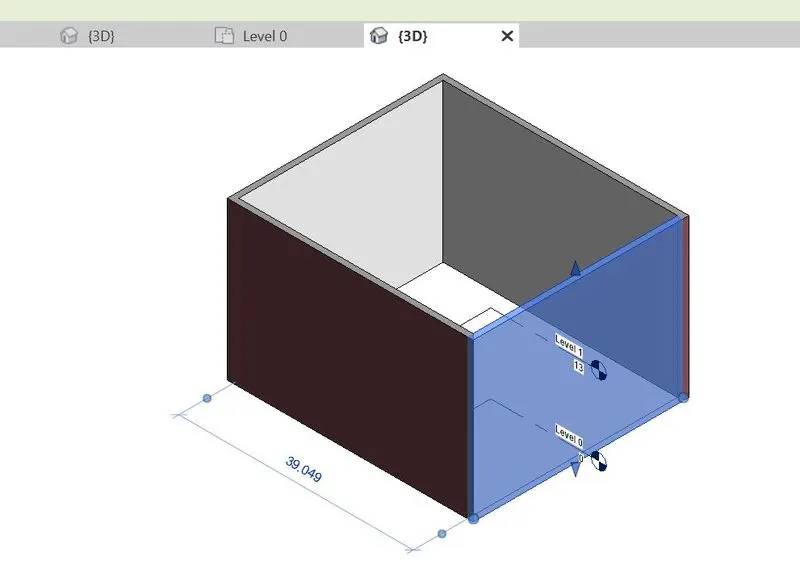
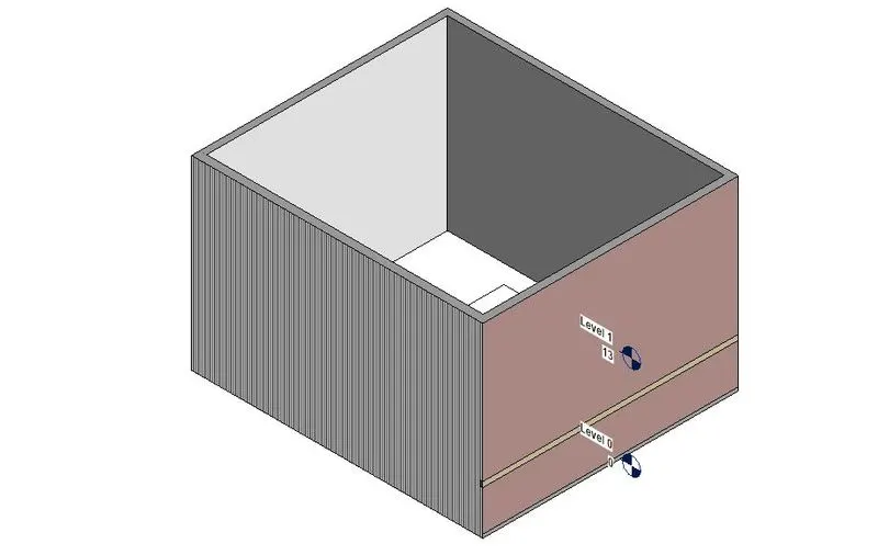
- Now select walls from the rectangular layout and change the different wall types
Result
A rectangular wall with different types of wall types are used, using the properties browser
6.
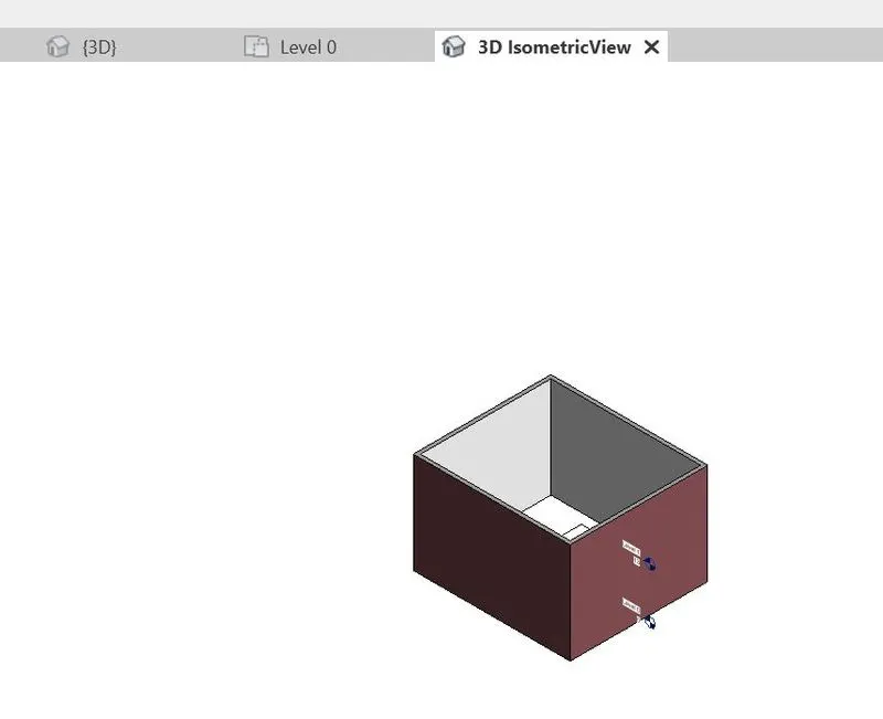
Aim: To create a 3D view from the view toolbar and to save the view with the appropriate name
Procedure:
- Open the Revit Software
- Now select the File toolbar, from that, select New option
- Select the project and select New Project
- Now the Template file tab will appear, select the construction template and click ok
- Now click the Architectural toolbar to create wall
- Now select the Architecture, and select the Wall option
- Now upon selecting the Edit Type, a new Screen appears asking for the edit requirements.
- Using the selected Wall, draw the rectangle layout of 40'0" * 35'0"
- Now Select the Anotate menu, and select linear dimension
- Select the default 3D view option to view in the 3D view
- Now point the curser on the view cub and the right click, a new tab appears and select Save View option
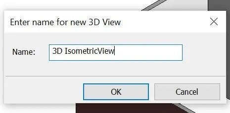
- Now enter the name of the 3D view in the new tab and click ok
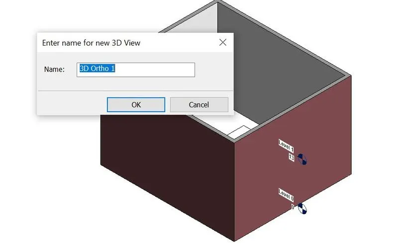
- Edit the name and save
Result
7.
Aim: To navigate through the 3D model using the view cube and orbit/pan through the model layout created
Procedure:
- Open the Revit Software
- Now select the File toolbar, from that, select New option
- Select the project and select New Project
- Now the Template file tab will appear, select the construction template and click ok
- Now click the Architectural toolbar to create wall
- Now select the Architecture, and select the Wall option
- Now upon selecting the Edit Type, a new Screen appears asking for the edit requirements.
- Using the selected Wall, draw the rectangle layout of 40'0" * 35'0"
- Now Select the Anotate menu, and select linear dimension
- Select the default 3D view option to view in the 3D view
- Move the cursor to the view cube and and can rotate to the required view position
- Now open the wheel shaped icon at the right side of the screen, and select the PAN / ORBIT option, hold and move the 3d model to view different positions

RESULT
The 3D model is nagivated using View cube, ORBIT and PAN.
8.
Aim: To use the visibility settings option below to switch model to shaded, realistic, hidden lines options
Procedure:
- Open the Revit Software
- Now select the File toolbar, from that, select New option
- Select the project and select New Project
- Now the Template file tab will appear, select the construction template and click ok
- Now click the Architectural toolbar to create wall
- Now select the Architecture, and select the Wall option
- Now upon selecting the Edit Type, a new Screen appears asking for the edit requirements.
- Using the selected Wall, draw the rectangle layout of 40'0" * 35'0"
- Now Select the Anotate menu, and select linear dimension
- Select the default 3D view option to view in the 3D view
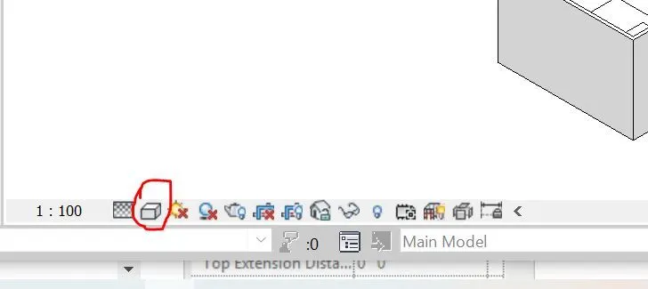
- Now from the graphic display setting option, select the Realistic option
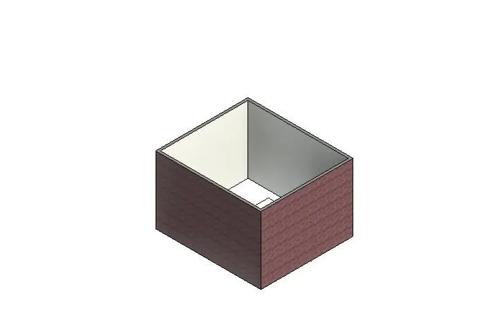
- Now again change the visibility of the 3D model to Shaded option
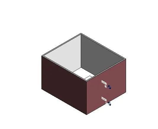
- Now again lets change the visibility to Hidden line
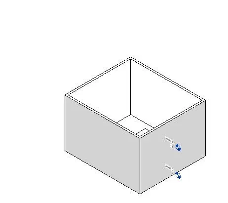
RESULT:
Switched the visibility of the 3D model to Realistic, then to shaded and then to hidden
9.
Aim: To Turn the sun path on and off to view shadings in the layout created
Procedure:
- Open the Revit Software
- Now select the File toolbar, from that, select New option
- Select the project and select New Project
- Now the Template file tab will appear, select the construction template and click ok
- Now click the Architectural toolbar to create wall
- Now select the Architecture, and select the Wall option
- Now upon selecting the Edit Type, a new Screen appears asking for the edit requirements.
- Using the selected Wall, draw the rectangle layout of 40'0" * 35'0"
- Now Select the Anotate menu, and select linear dimension
- Select the default 3D view option to view in the 3D view
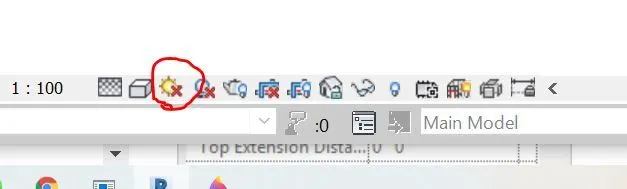
- Now click on the Sun Path icon at the bottom to open the Sun Path menu and select Sun Path ON
- Now, position of the sun, with time, month etc.
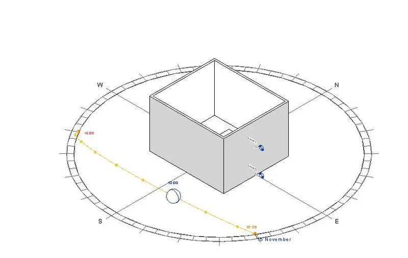
- Now again select
- the Sun Path icon at the bottom to open the Sun Path menu and select Sun Path OFF
RESULT
Turned the sun path on and off to view shadings in the layout created
10.
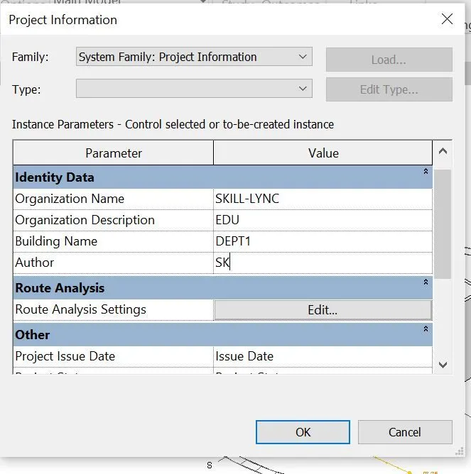
Aim: To use the Manage toolbar to enter project settings, project name, and project issue date
Procedure:
- From the Manage tool bar, select Project information
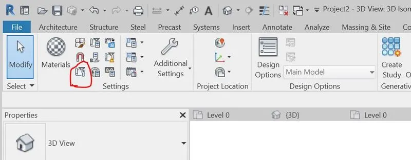
- A new tab opens
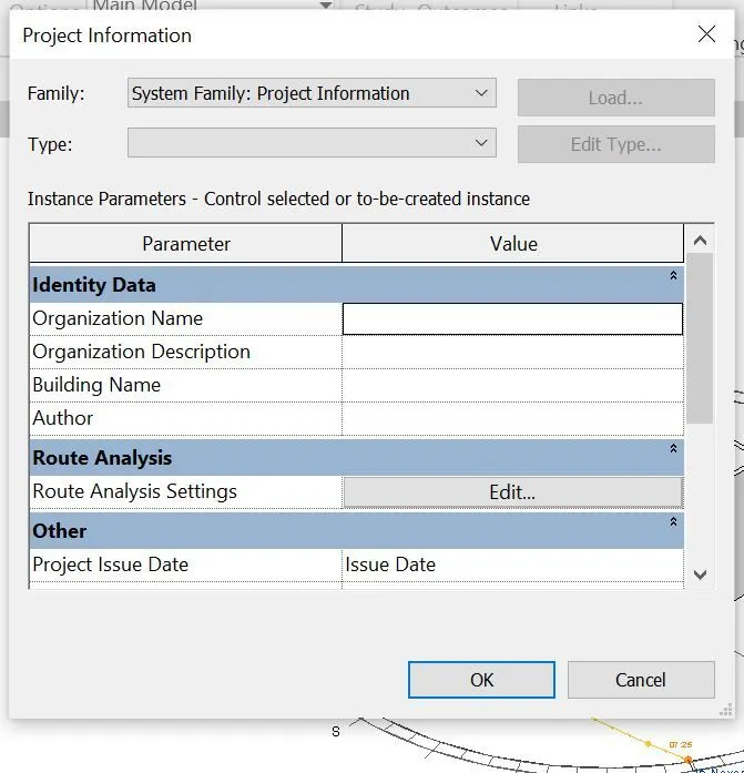
- Enter the required data of the projects in the appropreate coloumn
RESULT
The data given will be entered in the project information
11. Analyze toolbar helps us to analyse the structural building. The boundary conditions enables us to define point line, boundary conditions etc. in an analytical mode. This will verify the boundary coondition family types, that are loaded and assigned in the parametric features of the structural model. We can apply point load to a model as well, to evaluate the performance of the building, we can add, edit and combine different loads as well.
Benefits for Design and Modeling
- It helps to add, edit and even combine different load as well as different combinations of loads,
- This helps to evaluate the sustainability of the building created.
- Based on the conceptual masses, we can create an energy analytical model from the features.
- The quantity analysis can be done
- The materials used, building elements, etc used in the project can be evaluated
12. The links that Revit supports to be linked to the model are:
- LINK IMAGE : This allows us to link an image for the Revit model
- LINK PDF : This allows us to link the PDF file to the Revit model.
- DWG MARKUP : This links the markedup DWF files into the present Revit project so that we can see the markups in thhe corresponding sheet.
- LINK REVIT :This allows us to link another Revit model to the current model, so as to avoid repeated drawing, thereby increasing the easiness and convinience of the user.
- LINK CAD : A 2D Cad file can be linked to the Revit to produce a 3D model of the same using the Revit tools
- LINK IFC : This allows to link an IFC file to current project for the rinformation that is required for additional design works.
- POINT CLOUD : This links a point cloud file to the current Revit project
- MANAGE LINKS : This manages the links like CAD, DWF drawing files, and other BIM works
13. Collaborate tab enables collaboration, so team mebers can work on a model simultaneously. There are several ways to share project work or information with other team members, like through worksharing.
This enables the work more easy and to get a complete aspect, that people from different team can also work, and can make suggestions on the model and users can also work on same local network in the same Revit project. And multilple projects can be worked on Revit, together, giving a better understanding between the team members itself. This improves the efficiency of modeling.