Introduction to REVIT concepts
1.INTRODUCTION OF REVIT
- REVIT is an engineering configuration and documentation programming application.
- It is a building information modeling software for architects, landscape architects, structural engineering, mechanical, electrical, and plumbing engineering, designers, and contractors.
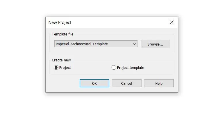
Step by step procedure for creating new projects
- Choose the option of file from a home page.
- Click, NEW’ as follows to have some criteria for open the different way of a project.
- Continuously to choose the templates of whatever we need to like structural or architectural or construction.
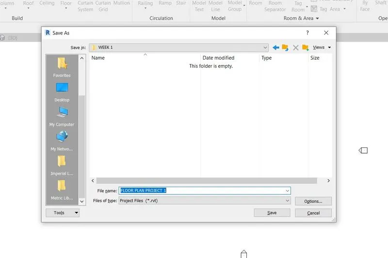
- And then to give the name for the same file in our storage.
- For file name is FLOOR PLAN PROJECT 1.

2.Close and Open icons
- Creating a new project .
- Given the name of the file.
- For here, using the Open icons for open the already existing file from different options like projects, family, revit file, building components, IFC options.
- For same from file browser, using the Close icons to totally save and exit from the current drawing.
3.AIM
To create a Rectangular wall with architectural toolbar by using the various commands in R EVIT.
INTRODUCTION OF WALL
- It’s a common basic important elements in diagram.
- Add one or more instances of a special type of architectural wall to the building model.
- Instances of predefined system of standard varieties of wall function, composition and thickness.
- It’s a inherent the material of other elements to which they are joined.
PROCEDURE
- To create a new projects and saved the file name.
- Take ,, wall’ from the tool bar, to draw the required wall of the given dimensions of buildigs.
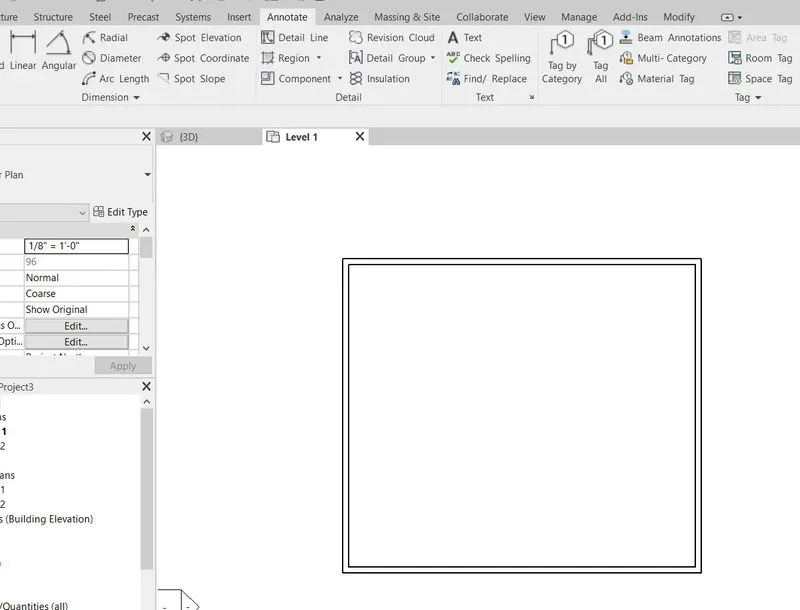
- Create a rectangle layout of wall at dimensions of 40’0” X 35’0”.
- For architectural wall is non load bearing wall and structural wall is load bearing.
RESULTS
The diagram of the rectangular wall is drawn by using the software of REVIT.
4.Dimensions to the layout
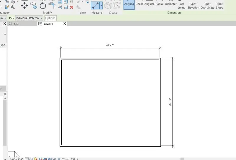
- To create the rectangular layout of the given dimension of 40’0” x 35’0”.
- After that to follow the option of ANNOTATIVE from main tool bar.
- Here we choose the Aligned dimensions options to measure the distance between the parallel lines.
- For we select the aligned tool, then to move the crusher over the drawing parallel lines for that way to select the required point of area.
5.Properties browser to switch different wall types
- After creating the wall with a given dimension at anywhere
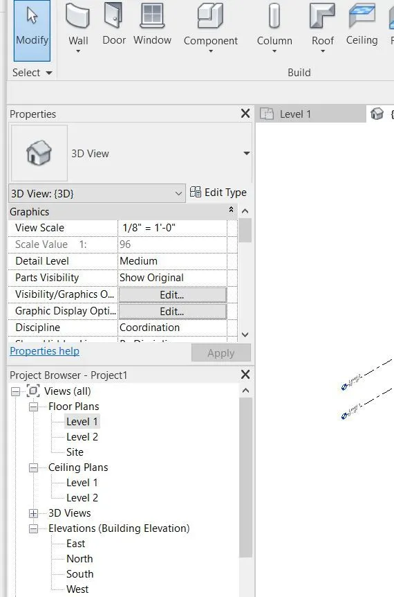
- Now we have to choose the properties browser to switch the different wall type for our convenient styles.
- This is used to specify the type of wall to create it, or use the default type to create a generic wall and specify a different wall type.
6.3D VIEW
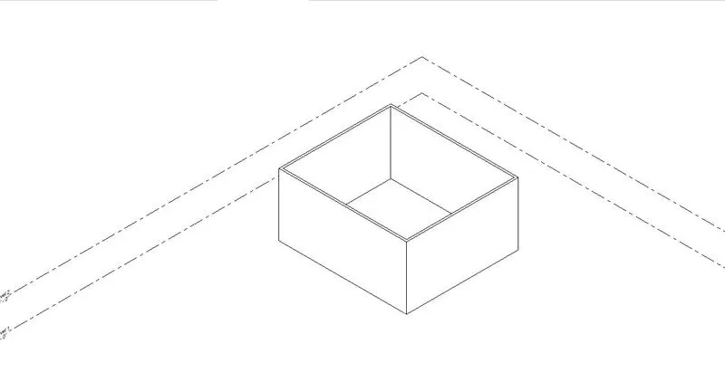
- To create the diagram of given dimensions.
- Then, to choose ,, VIEW, from main tool bar.
- After that to follow take the option of 3D view, then automatically the diagram change the 3d view in all direction and rotations.
- To use the view cube to change the orientation the view.
7.Navigation of 3D view.
- The navigation bar provides access to 2D and 3D navigation tool.
- Such as the view cube and autodesk steering wheel using the navigation bar.
- The navigation bar displays in the drawing area , along one side of the current model windows.
- The main navigation tool is orbit and Pan.
- The Orbit options to provides interactive viewing in 3D with the mouse.
- To take the Pan options, for when the pan tool is active , the pan cursor ( a four side arrows) displays.
8.Use the visibility setting
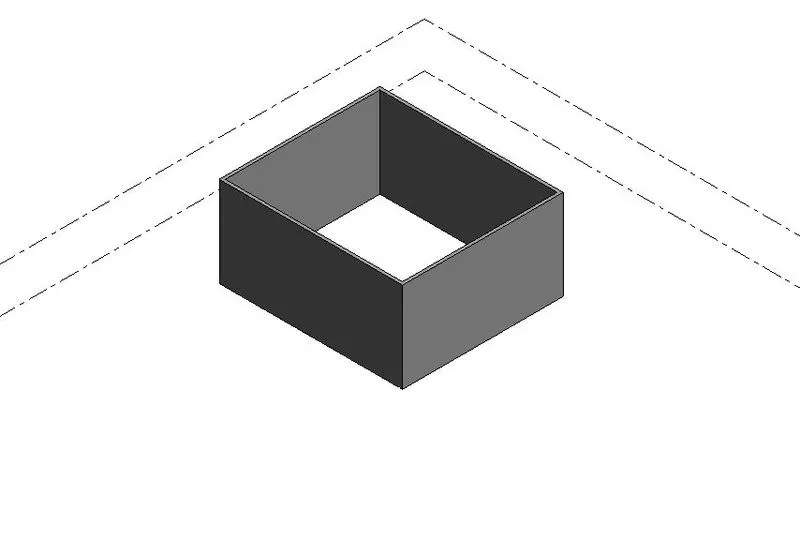
- Shaded – The options for shaded viewport plotting give you flexibility in conveying yoir design intent by choosing how viewport are plotted and by specifying resolution levels.
- Realistic – for choosing this option to view the realistic view of plotting diagram.
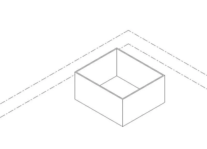
- Hidden - for choosing the hidden view of 3d to hide the line in between the crossing of corners.
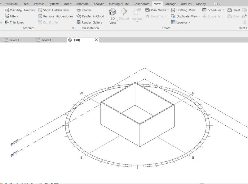
9.Sun path ON and OFF
- The sun path is a visual representation of the sun’s range of movement across the sky at the geographical location specified for the projects.
10.Manage toolbar
- From the main toolbar, to choose the manage toolbar for use to change the all properties, name , issues of the current and existing diagram.
- There are lots of different tools in manage toolbar
- Materials browser is used to find the materials to apply families or to model elements.
- Objects style to change specifies line weights, colors, patterns and material of model objects, annotation objects and imported objects.
- Projects parameters that can be added to categories of elements in a projects and used in schedules.
- Similarly to use the shared and global parameters.
- Additional settings to customize items such as units, line style, located tags, keynotes and objects styles for a project.
11. Analyze toolbar
- The analyze toolbar used in beneficial for design and modeling.
- This tool helps you to perform analysis on our structural building.
- The boundary conditions enable you to define point line and area boundary conditions in an analytic model.
- For here performs the analysis of loads for each geometry is a family contains instance and all type parameters, and also to analyze the load cases, load combination.
12.Links of revit to model
- REVIT links – for you can link models together to specify the relative locations of individual buildings on a campus, or to coordinate efforts across disciplines.
- IFC Link – links an IFC to the current project to reference its information for additional design work.
- CAD link – Linking is similar to having an xref in autocad, when the original linked file changes, these changes are reflected in the file when you reload the projects.
- LINK TOPOGRAPHY – for use this tool when a civil engineer has created topography using civil engineering software, such as Autodesk civil 3D , and you want to use the topography to provide context for the building model.
- Managr Link – this is the options of provide managing tools to buiding models, CAD files, DWF markup files and point clouds.
13.Collaborate Tab
- Its manage the collaboration panel.
- If you have installed the Revit cloud worksharing ad on, then : click collaborate tab manage collaboration panel collaborate.
- In the collaborate dialog, select collaborate within your network.
- It enables to team member can work on a model simultaneously.
- Its can able to edit and sync a model in the cloud, on a local area network.