Introduction to REVIT concepts
AIM : TO LEARN BASIC CONCEPTS OF REVIT
Introduction:
Revit is a Building Information Modelling software for architects, landscape architects, structural engineeers,
mechanical,electrical and plummbing(MEP) engineers, designers and contractors. Revit supports a multidiscipline design
process force collaborative design. Its powerful tools lets us to use the intelligent model-based process to plan, design,construct and manage buildings and infrastructure. The original software was developed by Charles River
Software, founded in 1997, renamed Revit technology corporation in 2000, and acquired by Autodesk in 2002. The software allows todesign a building and structure and its components in 3D,
aannotate the model ith 2D drafting elements, and access building inforation from the building models
database.
Revit is 4D building infortion modelling capable withtools to plan and track variousstages in the building's
lifecycle, from concept to construction and later maintenance and / or 1.
demolition.
Benefits of revit
Realtime 3D modelling programme
Evaluates performance
Optimization
Sustainability
• Parametric design
Revit in various disciplines
• Architectural design To visualize the project with different design solutions
• Structural engineering - To model 3D reinforcement designs and conduct structural
analysis
MEP engineering MEP stands for mechanical, electrical and plumbing and revit is used to model building systems and analyse its performance. Example-Duct and pipe system modeling, HVAC and electrical system design, duct/pipe sizing and pressure calculators, conduit and cable modeling etc
• Construction - To make preconstruction decisions which helps to minimise constructability risks and documentation of concrete designs
Collaboration tools in revit offers to work all these users simultaneously
Limitations
Revit avoids duplicate elements and creates no repetition. Revit avoids uncertainity in modeling.
Aim: To create new project and name the project appropriately.
Procedure: Initially open the revit software. Then go to new option in the model.Choose architecture
template, then click on project and then OK. Now, the Revit software opens.
Then, click on the save icon i.e (right most icon) which is on the left side of the screen. Then, a window opens. Now, type the desired file name and save it in the desired location.
Hence, the file name is saved as "Challengel.1".
RESULT:
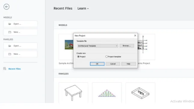
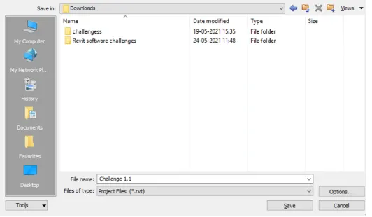
2. Aim: To save a project file. Then, close and open the file using icon from file toolbar.
Procedure:
Open the revit software and click on new. Then choose
architectural template, create new project and then OK. When the revit file opens click on the save icon (the
rightmost icon). Then a window opens.
Type the desired file name and save it in the desired
location.
Hence, the file name is saved as "Challenge 1.1". Now, we have to close and open the file using icons from
file toolbar.
So now, close the revit file.
Again open the revit software.
Then, go to file menu and click on open. From the open menu, open the file named "
Challengel.l'.Click open, hence the file is opened.
RESULT:
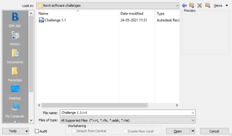
closing and opening file

3. Aim: To familiarise with the options to draw a wall from architectural or structural toolbar, then to create a rectangular layout of a walls of about 40'x35'.
Procedure:
Then choose the imperial template. Then go to the Architecture panel where you have
Initially open the Revit file. variety of options to develop a structure. Choose the wall option in the Architecture panel. Create a rectangular wall of 40'x35'. Hence, the 8" thick wall is created.
RESULT:
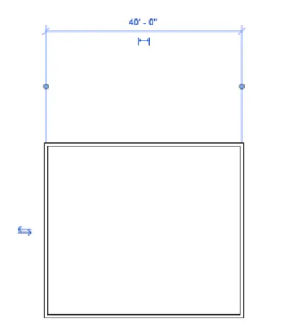
4.
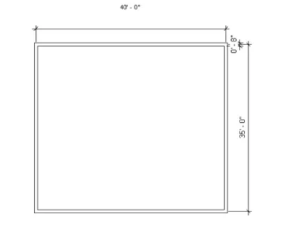
Aim:To dimension the wall layout by using the aligned option in annotate toolbar.
Procedure:
Initially open the Revit software.
Create a wall in the imperial template as given below. Now, go to annotate tab, choose aligned dimension. Then, provide the dimension to the wall thus created
RESULT:
5.
Aim: To use the properties browser to switch between different types of wall.
Procedure:
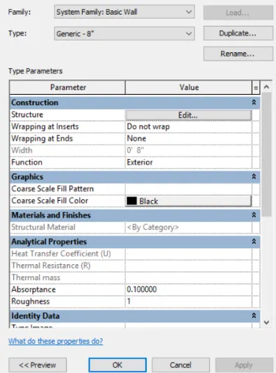
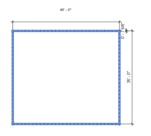
Initially open the Revit software. Create a wall in the imperial template as given below. Now, select the wall createdand then go to properties panel in the eft side of your drawing area.
In that, go to edit type option where you can change the
wall types.
Here the wall type is changed to generic 8"
masonry.Similarly different wall types can be chosen.
RESULT:
6.
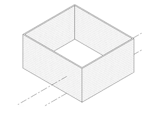
Aim: To create the 3D view from the view toolbar and then save the view with appropriate name.
Procedure:
Initially open the Revit software.
Create a wall in the imperial template as given below. Now we have to create the 3D view of this wall. For this go to view tab and choose 3D view option. Hence, the 3D view is developed as given below.Now, we have to save the view, for this click the full navigation wheelon the navigation bar. Then, right click the steering wheel and click save view. Now, enter a name for the new 3D view and then click ok. Hence, the view is saved.
RESULT:
7.
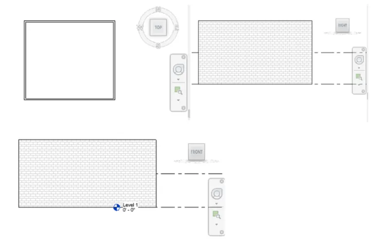
Aim:To navigate through the 3D model using the view cube. Orbit/pan through the model layout created.
Procedure:
To orbit/ pan we have to click on the view cube and then change the orientations to view different views. Similarly different views can be obtained by simply orbiting through the view cube.
RESULT:
8.
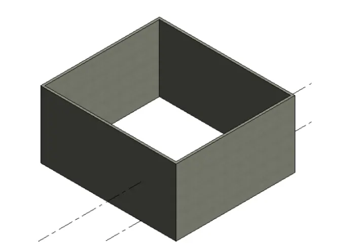
Aim: To switch model to shaded, realistic, hidden lines options by using the visibility settings options.
Procedure:
Take the 3D view of the wall.
Now, go to visibility section which can be accessed from
the below panel (2nd from left).
Presently the visibility is hidden, now we can change
visibility to shaded.Again change the visibility to realistic.
RESULT:
Hidden
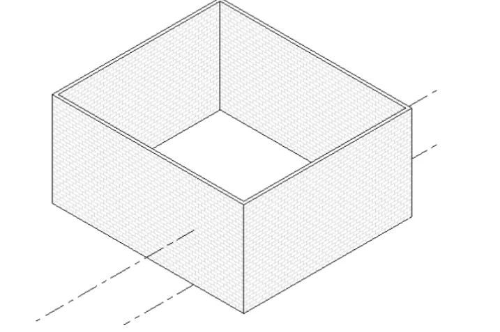
Realistic
Shaded

9.
Aim:
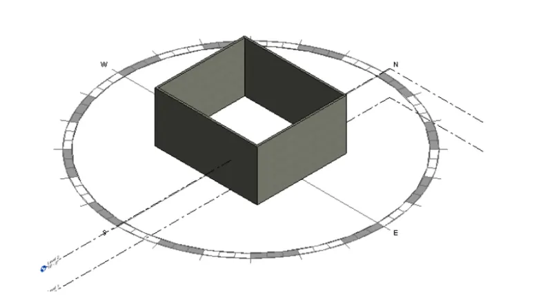
To turn the sunpath on and off to view the shadings in the layout created.
Procedure:
Create the relaistic view of the 3D wall. Now, make the sun on and off to view the shadings. Sun path off view:Sun path ON view:
RESULT:
sun path off
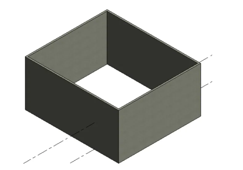
sunpath on
10.
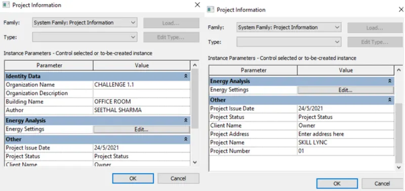
Aim: To use the manage toolbar to enter project settings, project name and project issue date.
Procedure:
Go to manage toolbar.
In this choose project information .Now, fill in the
necessary data.
Now, click ok. Hence completed.
RESULT:
11.
Analyze toolbar in Revit :
Analyze toolbar can be used to peform structural analysis of the building. It has various options that enables the analysis.- Various analytical model tools
are:
The boundary conditions option enables to define points, line and area boundary conditions in an analytical model.
Varifies that the boundary condition family type are loaded and assigned in the structural setting menu. Loads option applies point, line and area loads to a model. Each load geometry is a family containing
instances and type
parameters. Applies load by sketching or using host
components.
Load cases: adds and edits load cases for the anlaytical
model.
Load combinations: adds and edits the load
combinations for the analytical model. Setting a load
combination
includesdefining its name, formula, type, state and usage.
- Other analytical model tools are: Adjust: Adjusts the analytical model of the structural
member in relation to those of the elements to which it joins. Some
adjustments of the anaytical model locations may be equired before a structural model is transferred to
analysis and
design software.
Reset: Resets the analytical moel alignment methods to
Auto-detect. Auto-detects removes both projections
and manual
adjustments from the anlaytical model.
Supports: Verifies that the structural elements sucha s beams, columns, walls and slabs are joined to supporting elements.
Analytical model tab of the structural setting contai/ the criteria for checking member supports. elements such a foundations and boundary conditions can provide support for other elements.
Consistency: Verifies the analytical and physical model for consistency. Examines warnings and make changes
to the model as needed to rectify. The analytical model tab of the structural settings contains criteria for
consistency analysis. - Space & zones tools:
Space separator: Draws a separaton line to divide space. These lines are special model lines that are space bounding. It is
used to divide space for different heating and coling
reuirements. These are visible in plan and 3D views.
These space
separation lines are room-bounding, spce bundaries are determinedy the space separation lines along with other
Room
bounding components.
Space naming: Assigns the name and numbers from architecctural rooms to MEP spaces used for building performance analysis.
- Various other tools included in the analyze tab of the Revit software is given below:
- It is beneficial for design and modelling as it contains
variety of tools that enables the structural analysis of a
structure.
Various loads and load combinations that are likely to act in a structure can be determined from this toolbar. Further analysis can be carried out for its safety.
12.
Links that revit supports to be linked to the model: Link Revit: links another revit model to the current model.
Link IFC: Links an IFC file to the current project to reference its inforation for additional design works. If you later make
changes to the original IFC file and reload the link, the
project updates to reflect the IFC file changes. Link CAD: links a CAD to the current Revit project.Linking is similar to having an xref in AutoCAD. When the original
linked file changes, these changes are reflected in th
file when you reload the project. Link topography: links existing topography to the curre revit model. This tool is used when a civil engineer has created topography using civil engineering softwares,
such as Autodesk civil 3D nd you want to use the topography to provide context for the building model
DWF markup: Links marked up DWF files to revit projects so that the mark ups can be seen in the corresonding sheets.
Decal: Places an imge on the surface of a building
model for rendering. Decals can be placed on a flat or
cylindrical
surfaces in 2D & 3D orthographic views. Point cloud: Links a point cloud file into current project.
Coordination model: Links a NWD or NWC file to provide context for the revit model.
13.
Collaborate tab in revit:
Collaboration tab in revit enables worksharing. Through work sharing, users on same Local Area Network (LAN) can work
together in same Revit model. Multiple revit models can be linked together, allowing to
work in context.
When there is a need fro collaboration to occur amona
users who are not in the same geographic location,
Revit server
or Revit Cloud Worksharing.
Enabling worksharing involves creating a master proect model, known as a central model, from an exsting
model.