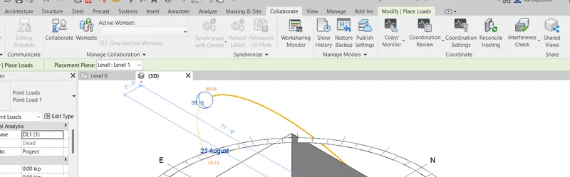
Introduction to REVIT concepts
1) From the file menu, create a new project (Structural / Architectural / Construction template ) and name the project appropriately
Ans 1:
AIM & INTRODUCTION: To create a new project from the file menu and provide the name to the project in Revit.
PROCEDURE:
- Open the Revit program
- From the main page click on File menu and then click New for opening new Revit Project File
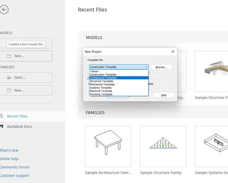
- New Project window will pop out
- Select the required template file from the drop down list either Architectural, Construction , Structural, Mechanical, Systems, Electrical, Plumbing or browse for required template
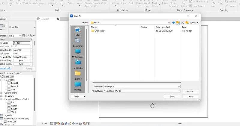
- On File menu click on Save As.
- The Save as window will pop up.
- Enter the required file name for the project
- Save in the required folder in the computer
CONCLUSION: Thus we have opened a new Project in Revit from the File menu and saved it in the Revit folder in computer drive by naming it as Challenge1.
2) Save the new project file. Close and open using icons from file toolbar
Ans 2:
AIM & INTRODUCTION: To save a new project from the file menu, close the Project and open using icons from the File toolbar in Revit.
PROCEDURE:
- Save the new project file from the File toolbar save icon
- Close the project file from the File menu
- Open the project from the folder by selecting the required Project file name
- Project can also be opened from the file menu by clicking Open and selecting the required file from the stored folder on computer
- Below are the screenshots for reference
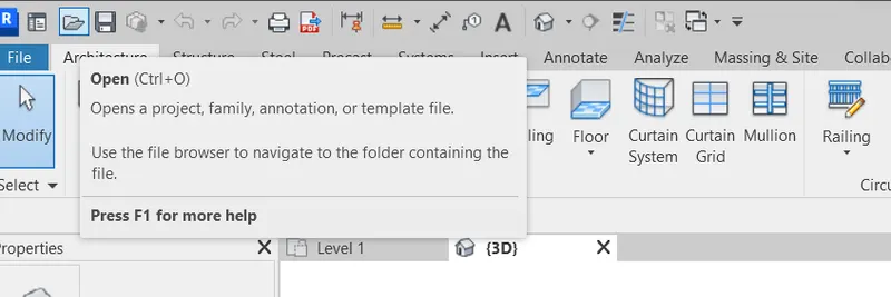
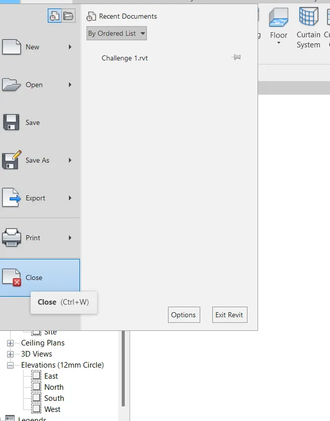
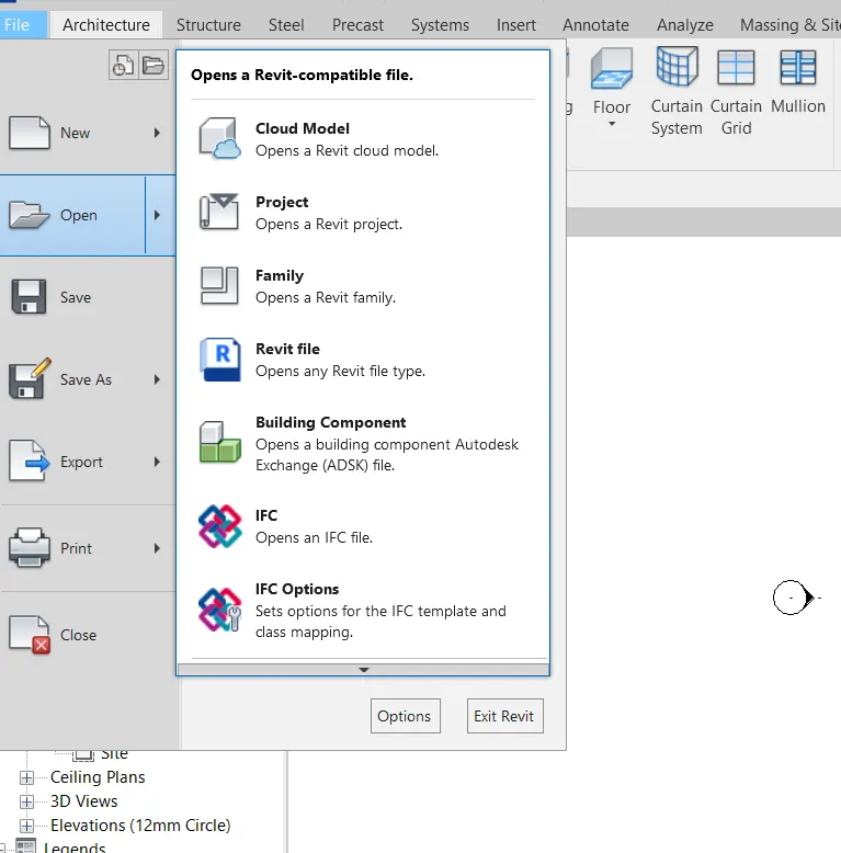
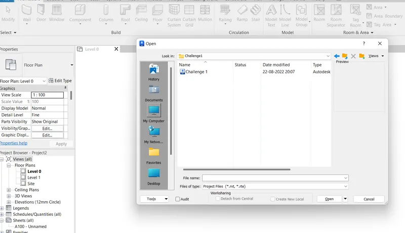
CONCLUSION: Thus we have saved the project file using save icon on the file tool bar, closed the project file and opened it using the Open icon on the File toolbar in Revit.
3) From the architecture/ structure toolbar familiarize with options to draw a wall. Create a rectangular layout of walls of about 40’-0” X 35’-0”
Ans 3:
AIM & INTRODUCTION: To create a rectangular layout of walls of 40' x 35' center distances from the Architectural or structural toolbar to familarize with the options to draw a wall.
PROCEDURE:
- Open the Challenge 1 project file with architectural template
- The units shall be set to English Imperial from the File Options
- Click the Architectural toolbar
- Click on Wall and select architectural wall
- Select 8' generic wall from the available wall options
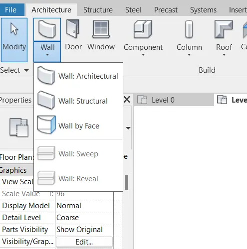
- Draw line for wall and enter 40' distance for first horizontal wall
- Continue drawing an 35' wall perpendicular to the 40ft wall
- Draw third side of 40' and close the rectangle with 35' wall
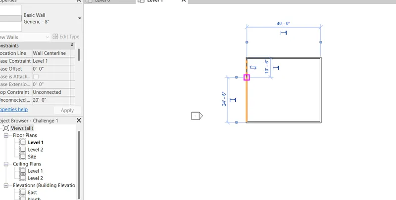
CONCLUSION: Thus the rectangular 40' x 35' wall layout of 8" generic wall is created using the Architectural wall in Revit.
4) From the Annotate toolbar use the aligned option to add dimensions to the layout
Ans 4:
AIM & INTRODUCTION: To provide the dimensions to the rectangular layout of walls of 40' x 35' center distances using linear as well as aligned options from the Annotate toolbar
PROCEDURE:
- On the Architectural wall drawing project file click on the Annotate toolbar
- Click on Aligned or Linear for providing the dimensions
- Select and click the first point of the line and the click on the second end point of the wall
- The dimesion line is created and place it at the require position by clicking away from the wall
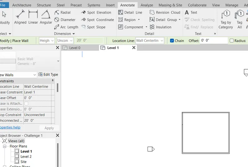
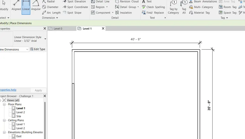
CONCLUSION: Thus we have provided the outer dimensions to the walls of the rectangular wall layout using the Annotate toolbar using aligned as well as linear option
5) Use the properties browser to switch to different wall types
Ans 5:
AIM & INTRODUCTION: To switch to different wall types to a rectangular layout of walls using the properties browser
PROCEDURE:
- On the rectangular wall layout drawing select the wall to be switched to other type by clicking on the wall
- The properties of existing 8" generic wall is shown in the properties browser
- Click on the 8" generic wall drop down menu on the properties browser then the other options of the walls will be listed down.
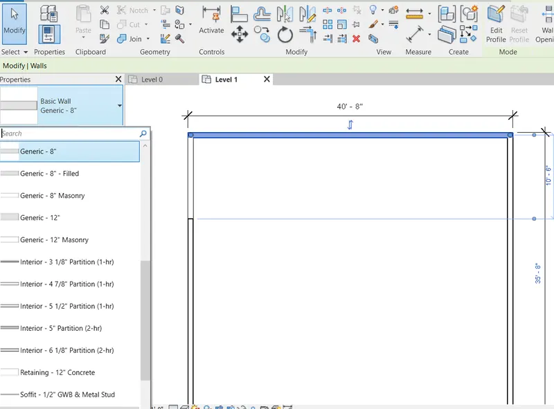
- Select the required wall to be switched, here it is switched to 12" Generic wall
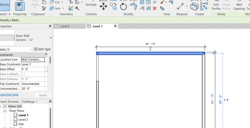
CONCLUSION: Thus we have switched existing wall in the rectangular wall layout from 8" generic wall type to 12" generic wall type using the properties browser.
6) Create a 3D view from the view toolbar and save the view with the appropriate name
Ans 6:
AIM & INTRODUCTION: To create a 3D view ot a rectangular layout of walls using view toolbar and save by giving name to the different views.
PROCEDURE:
- Select the view tool bar and click on the default 3D view option alternatively the default 3D view option form the top toolbar can be used to create the 3D view of the layout drawing.

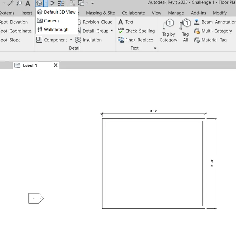
- The default 3D view of the rectangular wall layout is formed as shown below
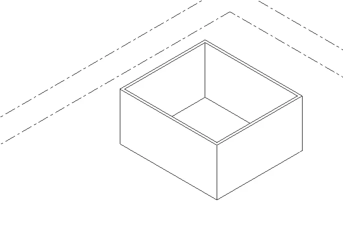
- The different views can be created using the view cube and by right clicking the cube the Save view option can be selected
- The name for the new 3D view can be provided and click on OK to save the view as shown below in screenshots.
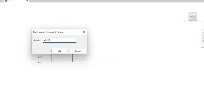
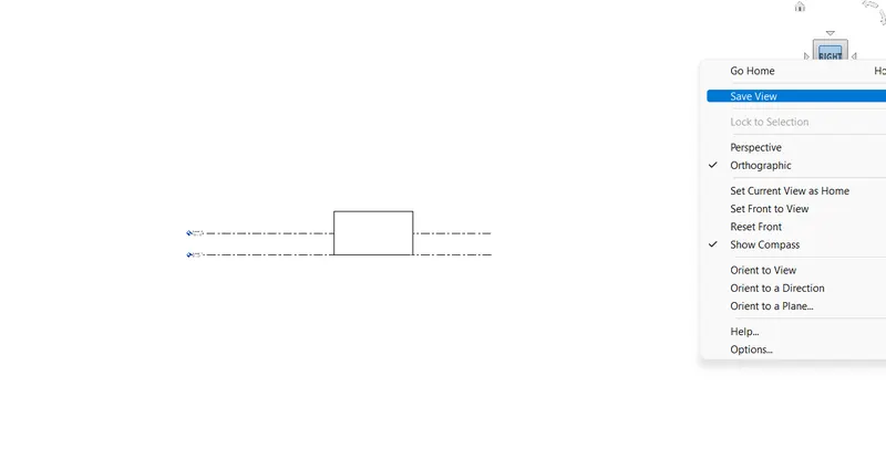
CONCLUSION: Thus we have created 3D view from the View toolbar and saved the views with View1 name.
7) Navigate through the 3D model using the view cube. Orbit/pan through the model layout created
Ans 7:
AIM & INTRODUCTION: To create the navigation bar from the user interface and navigate through the 3D model using the view cube. Orbit, zoom and pan etc available options to be used to navigate through the 3D model layout.
PROCEDURE:
- If the Navigate toolbar is not available on the drawing sheet, it can be created by using View toolbar and user interface option by ticking the on the Navigation bar.
- Click on the Navigation wheel and the 3D model can be orbited, panned, zoomed etc as per availabe options.
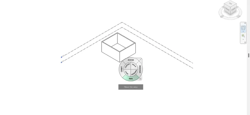
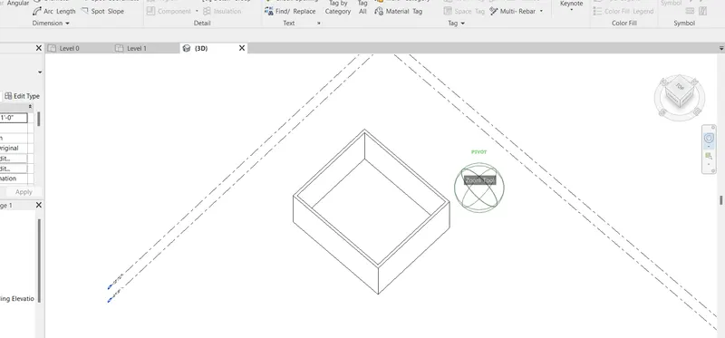
CONCLUSION: Thus we have used the navigation bar and navswheel to navigate through the 3D model and also the view cube is used to navigate through the different views option available on the viewcube.
8) Use the visibility settings option below to switch model to shaded, realistic, hidden lines options
Ans 8:
AIM & INTRODUCTION: To use the visibility settings option and viewing the 3D model using the various view options available.
PROCEDURE:
- Click on the visual style icon at the bottom
- Select the required view to be formed for the 3D model from the graphic display options
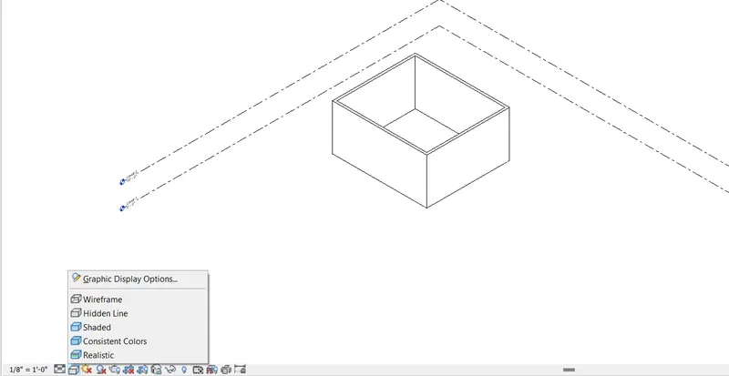
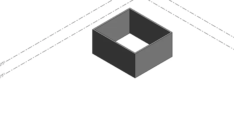
- Below is the shaded view.
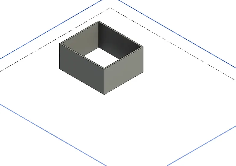
- Below is the realistic view formed.
- Below is the hidden view formed
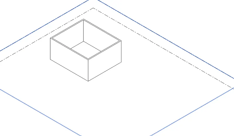
CONCLUSION: Thus using the visual styles option we have created the Shaded, Realistic and Hidden views of the 3D model.
9) Turn the sun path on and off to view shadings in the layout created
Ans 9:
AIM & INTRODUCTION: To use the sun path options by selecting on the sun path and creating the view with sun settings for the 3D model in Revit.
PROCEDURE:
- At the bottom select the Sun icon and turn on the sun path
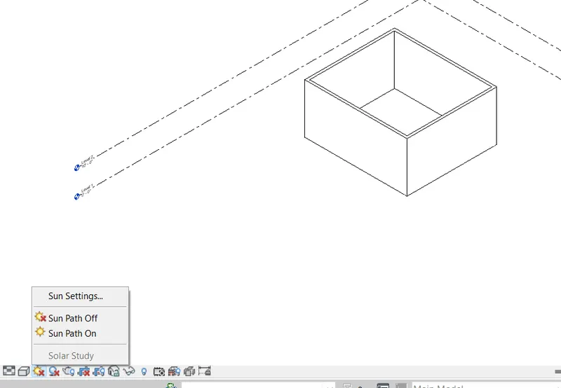
- The sun path is seen on the layout with the directions
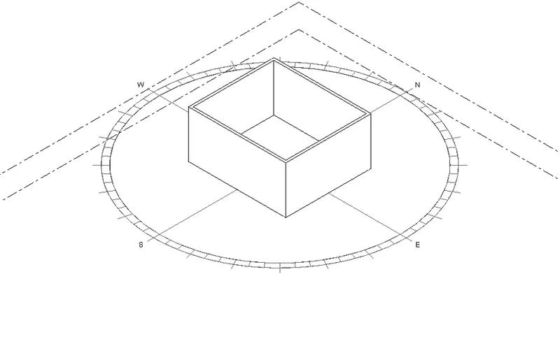
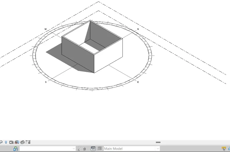
- The shaded option can be switched on the see the shades of the 3D model as per the sun position
- The sun settings can be adjusted for the location and site and for the required time and date settings for the selected location from the map.
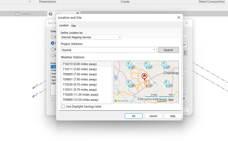
- The view for Nashik city in Maharashtra is selected for 23.08.2022 for the sun setting as shown below
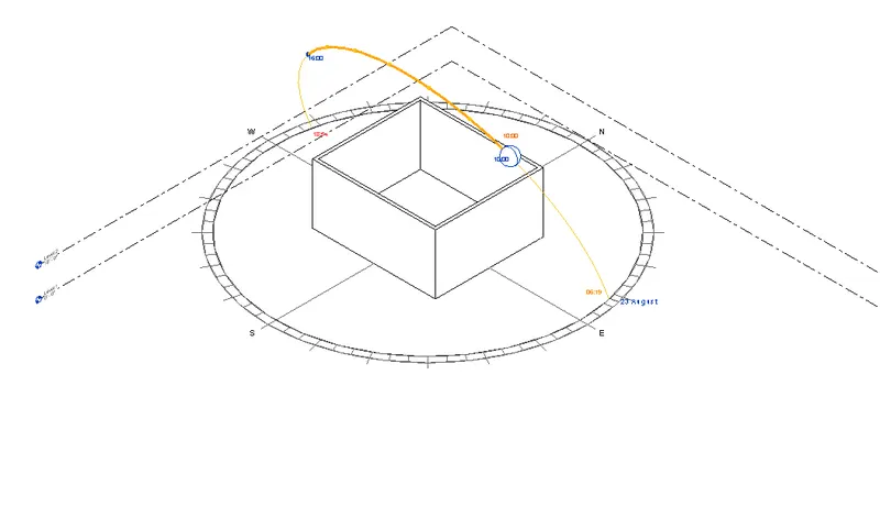
- The sun position can be moved to check the different shadow formations as shown below
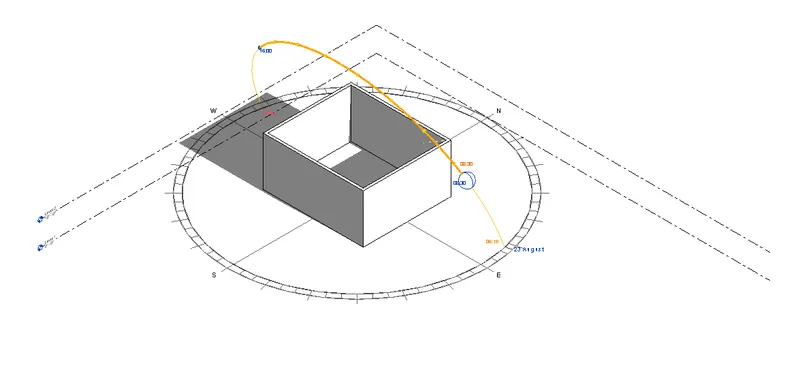
CONCLUSION: Thus we have used the Sun setting and created the sun path on the 3D model layoiut and viewed the shadings for the 3D layout created.
10) Use the Manage toolbar to enter project settings, project name, and project issue date (choose according to your convenience).
Ans 10:
AIM & INTRODUCTION: To use the Manage toolblar and enter the project settings, project name etc for the rectangular wall layout project created in Revit
PROCEDURE:
- Click in the manage tool bar
- From various options select the project information icon
- Enter the different data for the project information in the table like organisation name, decription, building name, author name, date created etc data required and click ok to assign the data to the project file.
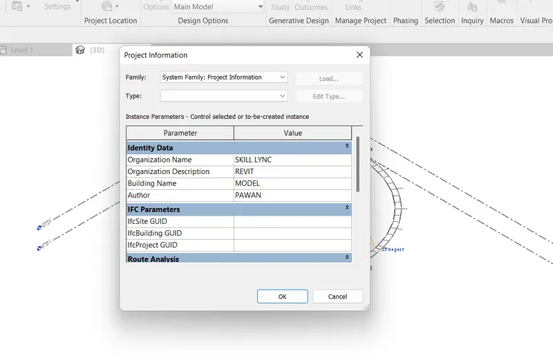
CONCLUSION: Thus using the Manage toolbar we have provided the project information to the rectangular wall layout project created.
11) What is the Analyze toolbar used in Revit? How it is beneficial for design and modeling
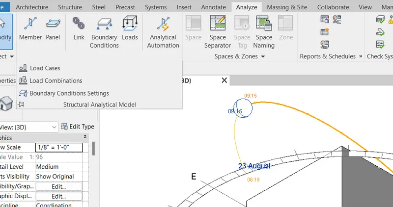
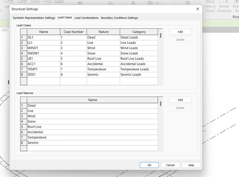
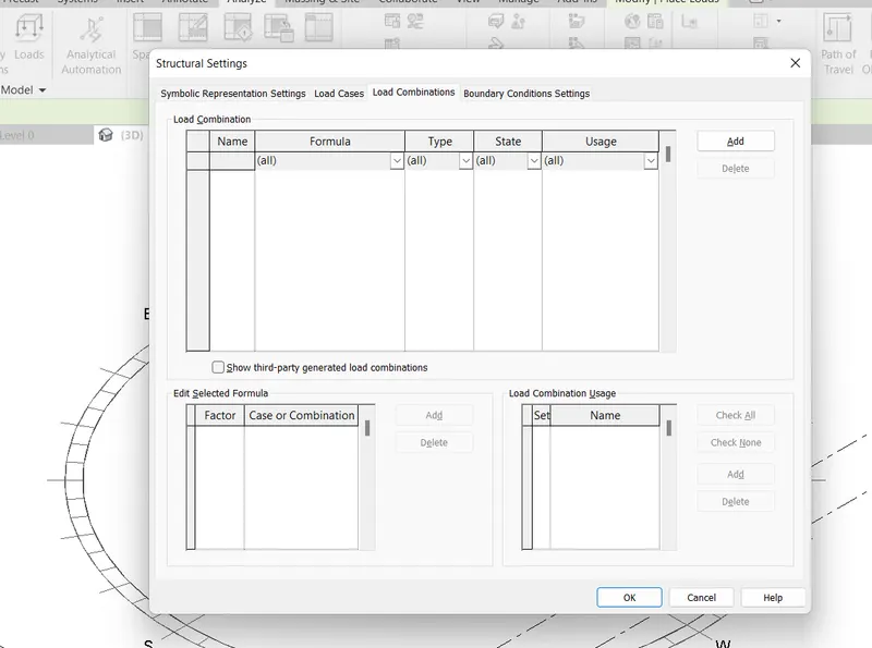
Ans 11: The Analyze toolbar in Revit is used to basically enter and analyze the load cases on the strutrural drawing, loadcombinations and boundary conditions on the members in drawing as a structural analytical model.
The screenshots of the Analyze toolbar options are shown below.
12) What are the links that Revit supports to be linked to the model?
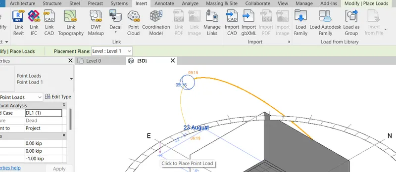
Ans 12: The links that Revit supports to be linked to the model are as mentioned below
- Revit models from other project or discliplines like Structural, Plumbing, Mechanical etc.
- IFC drawings linking to manage the project constrution
- Linking of the AutoCAD drawing already available
- Linking Topography of the land to create the project details
- And other options like DWF markup, Decal, Point cloud and Coordination model etc
The screenshot of the Link options in the Insert toolbar is shown below.
13) Why do you need the Collaborate tab in Revit? How it supports modeling and its efficiency
Ans 13: The Collaborate tab in Revit is required to collaborate the different disciplines of the project so as to check out the progress and avoid any clashing of different services and featrures by interference check.
It is also used for worksharing to monitor and control the actual progress at site
It is used to reflect and highlight the latest changes in different discipline
Thus it supports the Building information modeling and the efficiency of the work monitoring is achieved by avoiding the reworks by proper coordination within different discipline works.
The screenshot of the Collborate toolbar is shown below.