Introduction to REVIT concepts
1) From the file menu, create a new project (Structural / Architectural / Construction template ) and name the project appropriately.
Aim:
To create a new project from the file menu and name the project appropriately.
Introduction:
A new project is created from the file menu of revit with the appropriate name.
Procedure:
- Open revit software.
- Use open option open the new project with any of the template.
- Click the file menu.
- Click new and project option.
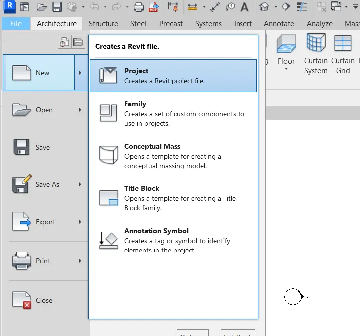
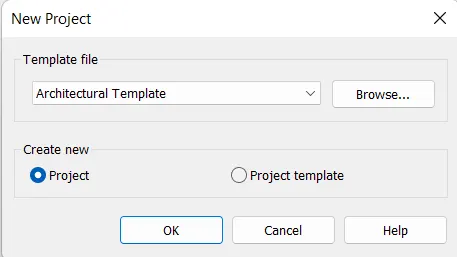
- Select the template and new project.
- Click ok.
- Click save option by using file menu.
- Name its as 'week 1 Q1'
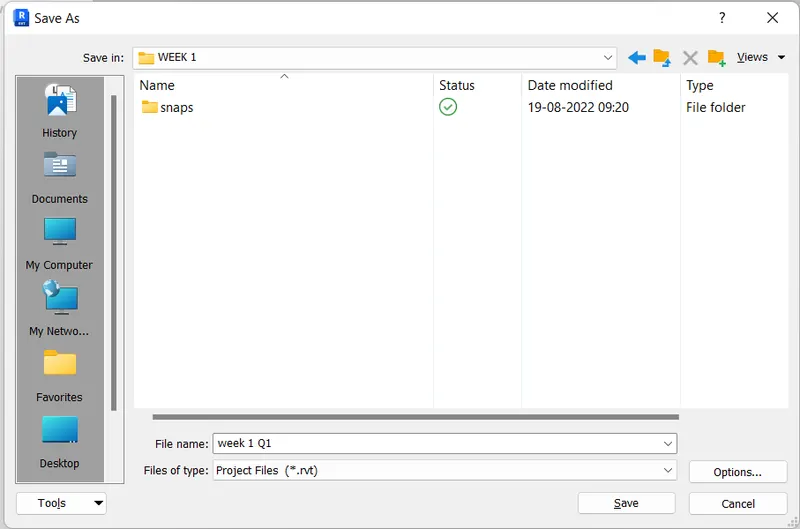
Result:
A new project is created from the file menu and name it as 'week 1 Q1'
2) Save the new project file. Close and open using icons from file toolbar
Aim:
To save the new project file. Open and close the file using icons from the toolbar.
Introduction:
Save the revit new project. By using the close and open icon from the toolbar open and close the file.
Procedure:
- Open the revit software.
- Create new project by using new option.
- Save the project in the name of 'week 1 Q2' by using save option in the file menu.
- Click the file menu Pick close option to close the file.
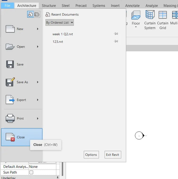
- Click open option in the home page.
- Select the file 'week 1 Q2' and click open.
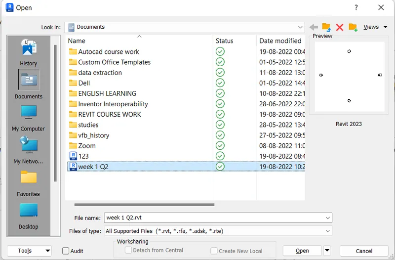

Result:
The new project file is saved. The file is again open and close by using the icons from the toolbar.
3) From the architecture/ structure toolbar familiarize with options to draw a wall. Create a rectangular layout of walls of about 40’-0” X 35’-0”
Aim:
To create a rectangular layout of walls of about 40'-0''X35'-0'' from the architecture/ structure toolbar.
Introduction:
The rectangular layout of walls of size 40'-0''X35'-0'' by using wall option available under the architecture toobar.
Procedure:
- Open Revit software.
- Open new project by architecture imperial tamplate.
- Select the wall architecture option under the architecture tab.
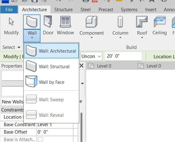
- Select wall type as 'Generic 12''
- Draw the wall of size 40'-0''X35'-0''
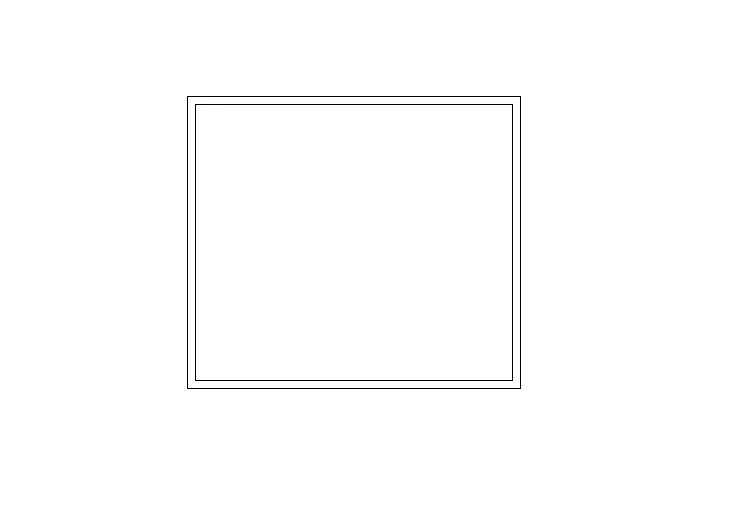
Result:
A rectangular layout of walls of about 40'-0''X35'-0'' from the architecture/ structure toolbar is created.
4) From the Annotate toolbar use the aligned option to add dimensions to the layout
Aim:
To add dimensions to the layout from the annotate toolbar use aligned option.
Introduction:
Dimensions is created by using the annotate toolbar by the use of aligned option.
Procedure:
- Open Revit software.
- Open the previously create wall layout project.
- Click the annotate tab.
- Click aligned option.
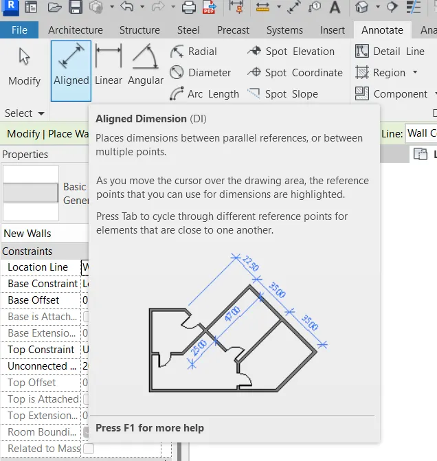
- Select the references to make the dimensions.
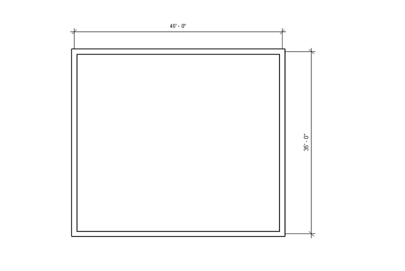
Result:
Dimensions to the layout is added from the annotate toolbar use aligned option.
5) Use the properties browser to switch to different wall types
Aim:
To switch the different wall types by using the properties browser.
Introduction:
Using the properties browser switch the wall types as Exterior-Brick on CMU and Generic-4'' brick.
Procedure:
- Open Revit software.
- Open the previously create wall layout project.
- Select the wall.
- Select the wall type in properties browser.
- Select Exterior-Brick on CMU.
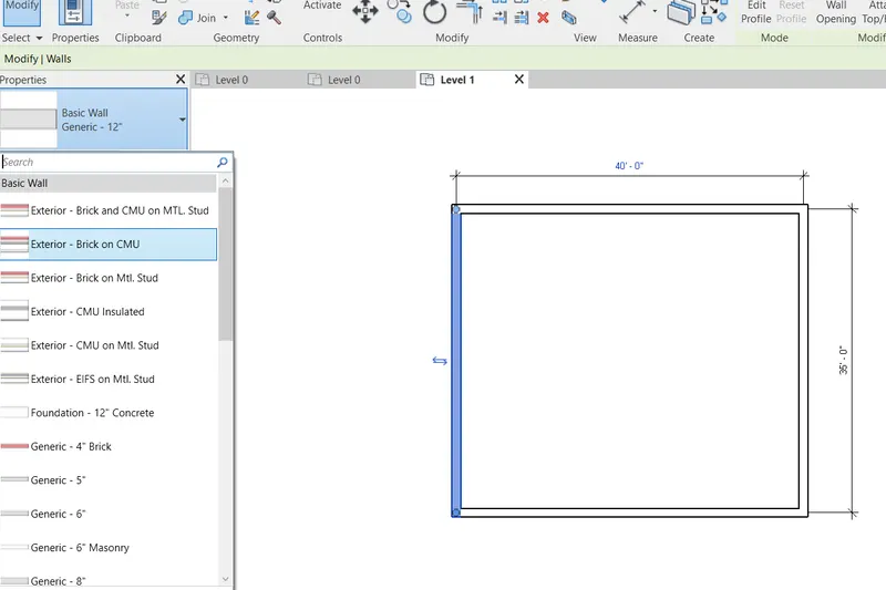
- Select another wall.
- Select the wall type in properties browser.
- Select Exterior-4'' brick.
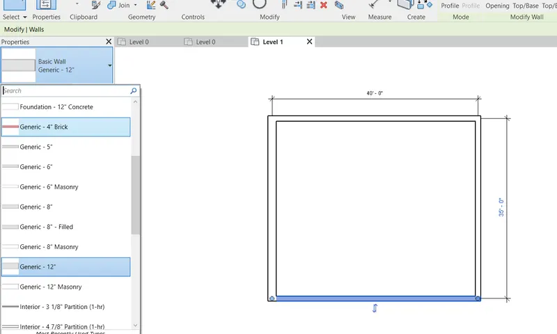
Result:
The different wall types by using the properties browser is switched.
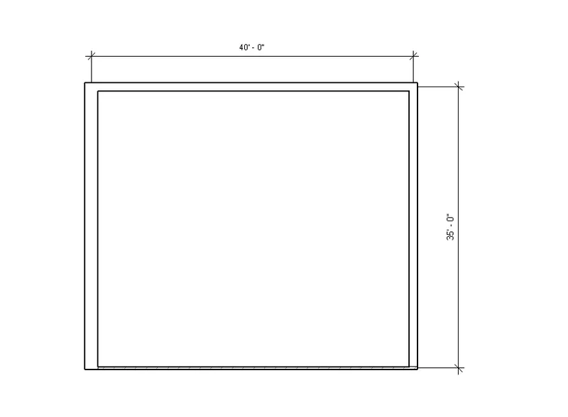
6) Create a 3D view from the view toolbar and save the view with the appropriate name.
Aim:
To create a 3D view from the view toolbar and save the view with appropriate name.
Introduction:
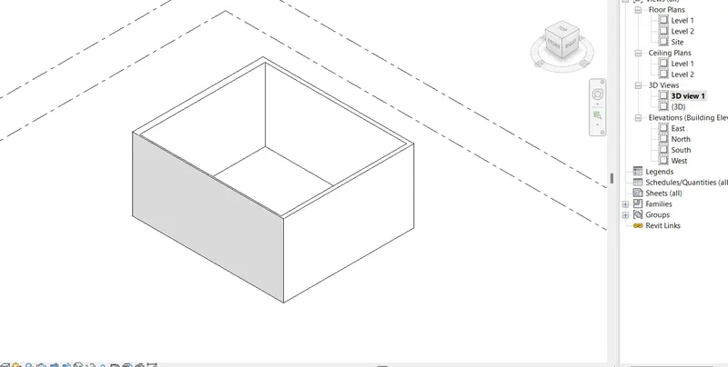
The 3D view of the wall of size 40'-0''X35'-0'' is saved with the name of 3D view 1.
Procedure:
- Open Revit software.
- Open the previously create wall layout project.
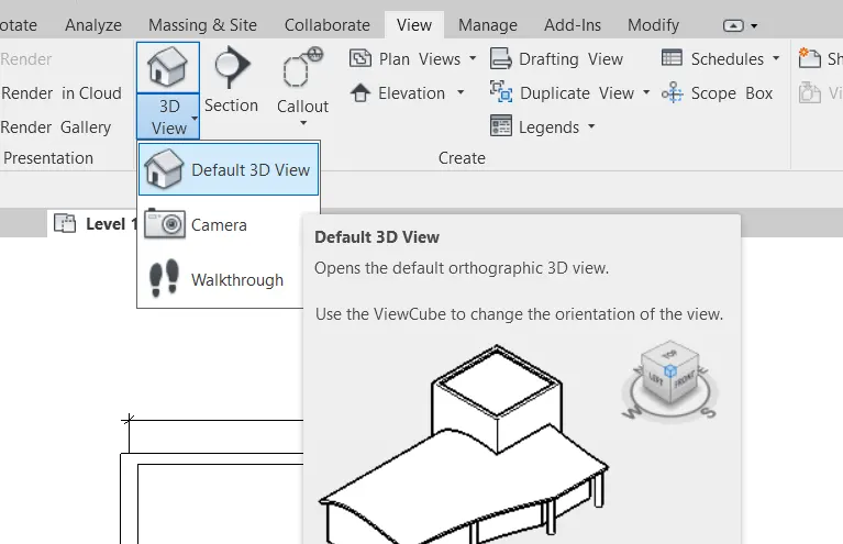
- Click the view tab.
- Click the drop pannel in the 3D view.
- Select Defalut 3D view.
- Hower the curssor to the view cube.
- Right click and select save view option.
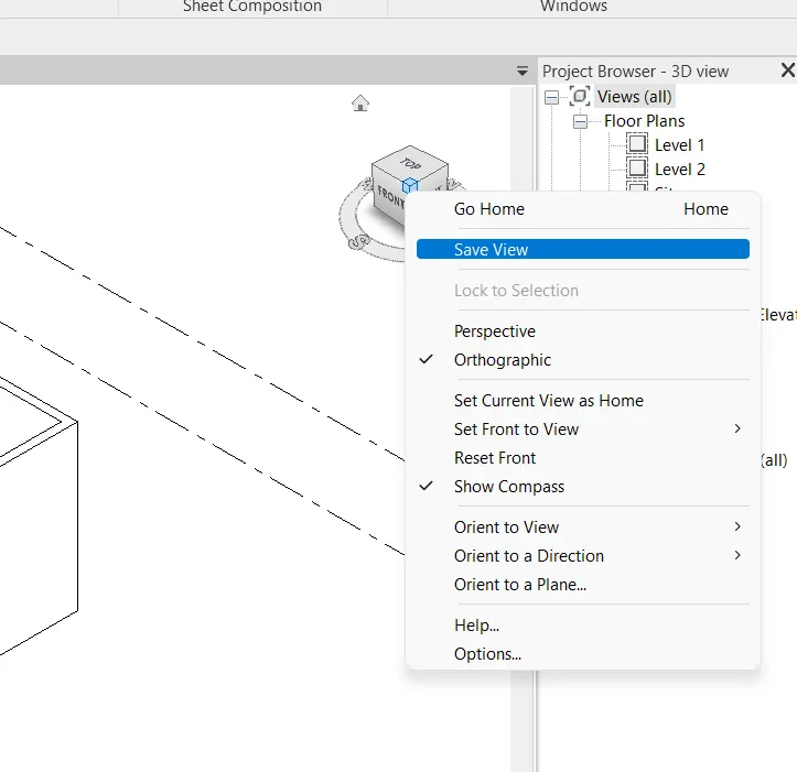
- Save the view name as '3D view 1'
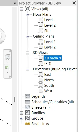
- The view is saved.
- Expand the 3D views in project browser.
- The saved view is their.
Result:
A 3D view from the view toolbar is created and save the view with name as '3D view 1'
7) Navigate through the 3D model using the view cube. Orbit/pan through the model layout created.
Aim:
To navigate through the 3D model using view cube and orbit/pan through the model layout created.
Introduction:
The view cube is used to view the 3D object in 360 deg or to set the particular view and orbit tool is used to see the 3D object in 360 deg. Pan is used is hover the model layout or 3D object.
Procedure:
- Open Revit software.
- Open the previously create wall layout project.
- Click the view tab.
- Click the drop pannel in the 3D view.
- Select Defalut 3D view.
- Click the view cube to rotate the object in 360 deg or click to set the particular view.
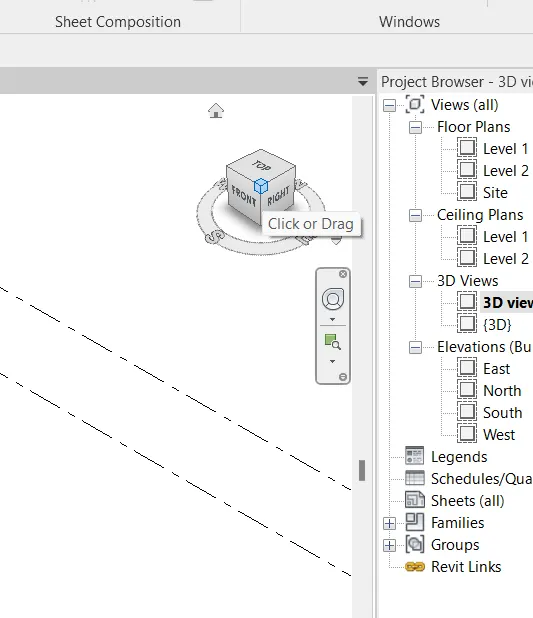
- Click the steering wheel in the navigation bar.
- Click pan to pan through the model.
- Click orbit to rotate the model.
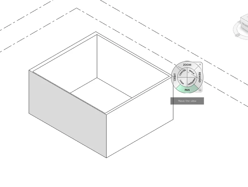
Result:
Navigate through the 3D model using view cube and orbit/pan through the model layout created is done.
8) Use the visibility settings option below to switch model to shaded, realistic, hidden lines options.
Aim:
To Switch the model to shaded, realistic and hidden lines Using the visibility settings.
Introduction:
The visibility settings is used to Create the model to shaded, realistic, hidden line, Wireframe na consistant colors.
Procedure:
- Open Revit software.
- Open the previously create wall layout project.
- Click the view tab.
- Click the drop pannel in the 3D view.
- Select Defalut 3D view.
- Click the visual style settings tool in the view control toolbar.
- Set the visual style as shaded.
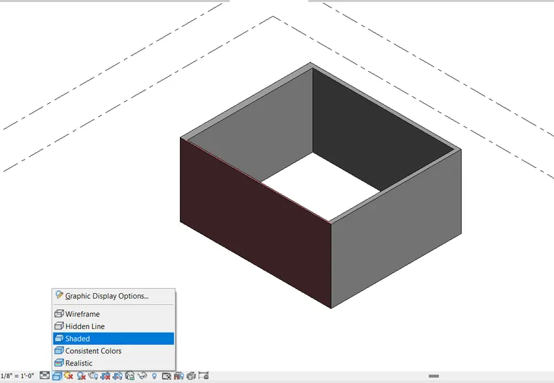
- Set the visual style as realistic.
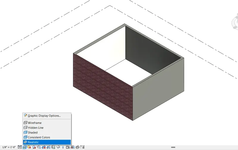
- Set the visual style as hidden lines.
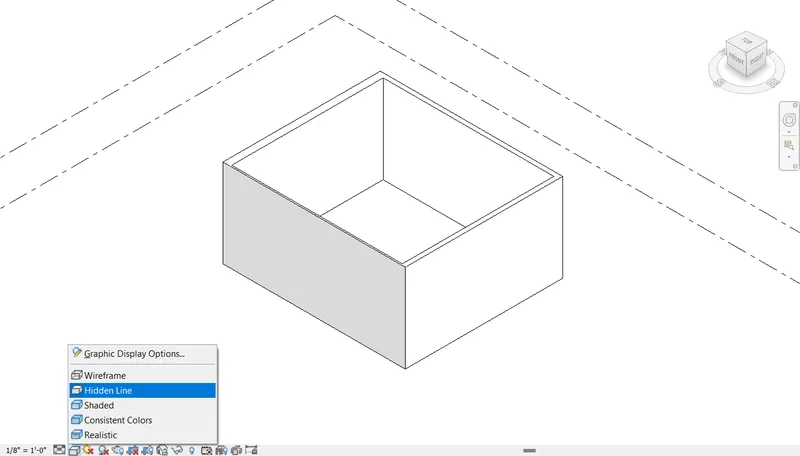
Result:
The model is switched to shaded, realistic and hidden lines Using the visibility settings.
9) Turn the sun path on and off to view shadings in the layout created.
Aim:
To turn the sun path on and off to view shadings in the layout created.
Introduction:
The sun path settings is used to set the sun in desired location to view the shadows in the created model layout.
Procedure:
- Open Revit software.
- Open the previously create wall layout project.
- Click the view tab.
- Click the drop pannel in the 3D view.
- Select Defalut 3D view.
- Set the visual style as realistic.
- Trun on the sun path and shadows located in the view control toolbar.
- The shadings in the created layout is visible.
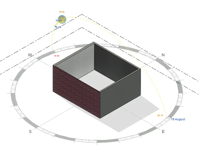
- Trun off the sun path to view the shadings.
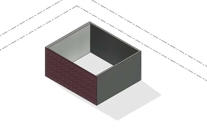
Result:
The shadings in the created layout is viewed by trun on and off the sun path.
10) Use the Manage toolbar to enter project settings, project name, and project issue date (choose according to your convenience).
Aim:
To use manage toolbar to enter project settings, project name and project issue date.
Introduction:
The project information in the manage toolbar is used to set the project name, client name, building name, author and other details.
Procedure:
- Open Revit software.
- Open the previously create wall layout project.
- click to open the manage toolbar.
- click project information.

- Enter the details of the project line project name, building name, author ect...
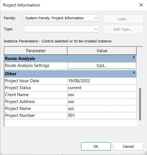
Result:
The use of manage toolbar to entred the project setting, project name and project issue date.
11) What is the Analyze toolbar used in Revit? How it is beneficial for design and modeling

Analyze tool bar is used to perform structural analysis of the building. It has various option to enable the analysis process.
- Boundary conditions
Boundary conditions enables to define poins, lines and area boundary condition in a analytical model.
- Loads
Applies point, line and area load to the model. Each load geometry is a family containing instenses and type parameters apply located by sketching or using components.
- Load cases
Can adds and edit load cases for the analytical model
- Load combination:
Can adds or edit load combination for the analytical model. setting a load combination includes defining its name, formula, types, state and usage.
12) What are the links that Revit supports to be linked to the model?

- Revit link
This links another revit model to the current model.
- Link IFC
Links an IFC file to the current project to reference its information and additional design work.
- Link CAD
Links a CAD file to the current revit project.
- Link topography
Links exixting topography to the current revit model.
- DWF markup
LInks marked-up DWF files into a revit project so we can see the markups on the corresponding sheets.
- Point cloud
Links a point cloud file such as .rcp or .rcs into the current project.
- Link PDF
Inserts a link to a PDF into a model view.
- Link image
Inserts a link to an image into a model view.
13) Why do you need the Collaborate tab in Revit? How it supports modeling and its efficiency
Collaborate tab enables the work sharing. Use work sharing users on same local area network can work together in a same revit model.
- Multiple revit model can be linked together its allowing to work in context.
- By enabling work sharing involves creating a master project model known as central model from the existing model.
- The central work model stores the current ownership information for all worksets and elements in project and act as a distribution point for all the changes made to the model. So, all the users should have the own copy of the central model they can edit localy in this workspace and they can also sync with central to publish changes the central model. so that other users can see the work.