Creating Architectural and Structural model with 3D rendering using REVIT
1) Select the type of structure you want to build from one of the three below:
a. Multi-Unit Residential Apartment
b. Office Buildings
c. School
Answer:
I have selected Option b. Office Buildings
2) Assume reasonable assumptions for geographic and location details for your project modeling. Based on assumptions and type of structure selected identify the modeling requirements from NBC
Answer:
- The Open Space around the building shall not be less than 4.5m
- The type of construction as type 2 construction, the FAR value for the business building shall be taken as 2.9.
- The plot size is taken as 73m x 37m i.e 2701 Sqm and individual floor area is 1761 Sqm. Hence, FAR value obtained is 1.96 which is within the prescribed limits as per NBC.
- The width of the road abutting the building is taken as 9m (30').
3) Using the structural model, include the following components based on the type of structure selected
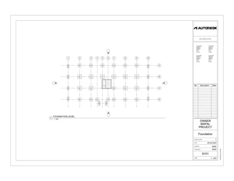
a. Foundation – Isolated / Wall/Matt Foundation
b. Columns
c. Beams Connected to Columns
d. Roof Framing/ Truss
e. Floor / Decks
f. Floor Openings for Elevators and Stairs
Aim:-
To create the components based on the type of Structure selected using the Structural model.
Introduction:-
- Structural model should contains Foundation, Columns, Beams, Floor & Roof.
Procedure:-
Step 1:-
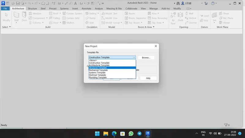
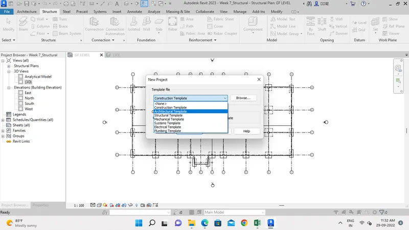
- Create a New Structural Template from the File Tab as shown below.
Step 2:-
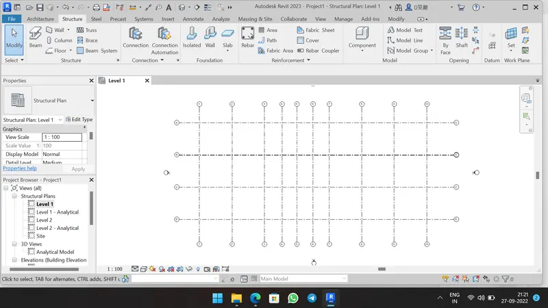
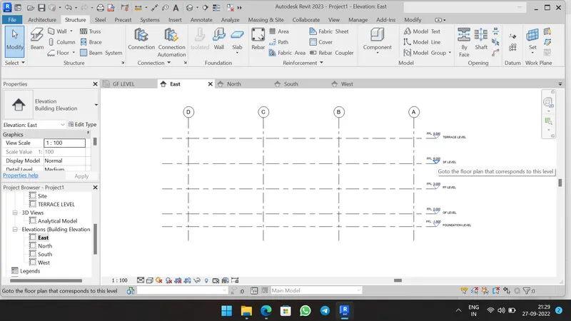
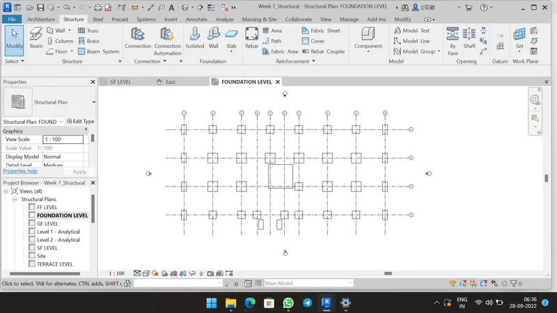
- To place foundation, create Levels and Grids from Struture Tab as shown below.
- In Structure Tab, select Isolated footing tool.
- Change the size required from Properties browser.
- And place the footing at appropriate location using At Grids option in Foundation level as shown below.
Step 3:-
- In Structure Tab, select Column tool.
- Change the column as required and rename it from Properties Browser as shown below.
- Set Top and Bottom constraints.
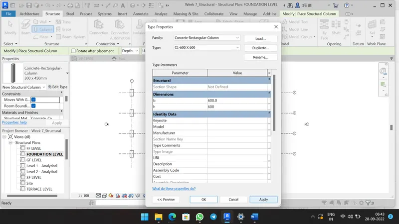
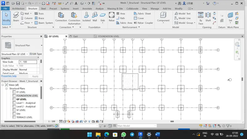
- Place the column at appropriate location using At Grids option as shown below.
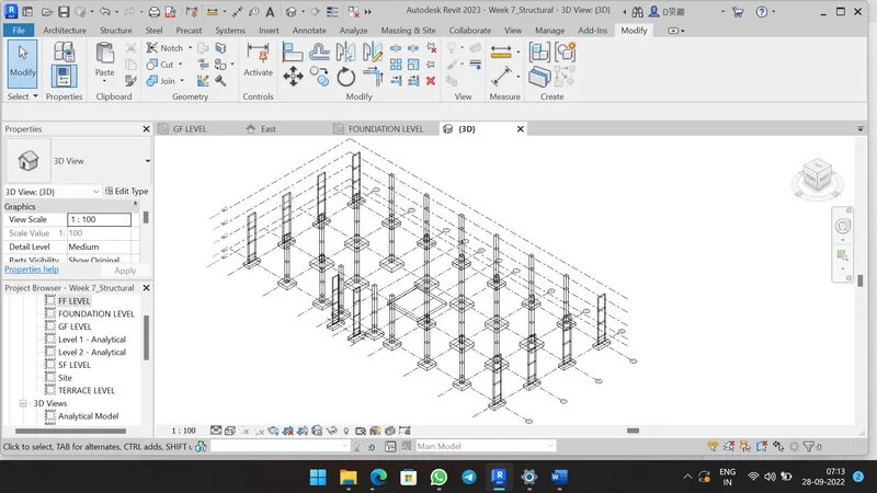
- Similarly place the columns at Ground Floor level.
- And copy the columns to the another levels by paste as Assigning to selected level option.
Step 4:-
- In Structure Tab, Select Beam tool and pick Concrete rectangular beam.
- Change the size of beam as required from Properties browser and rename it.
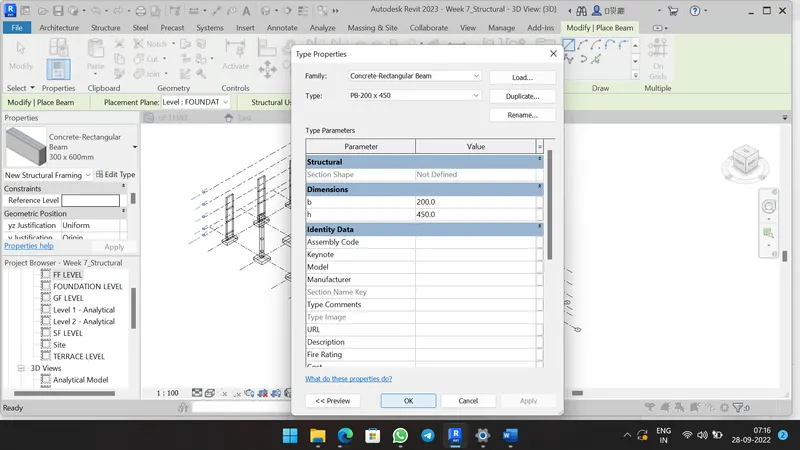
- Place the Beam at location in Ground Floor as shown below.
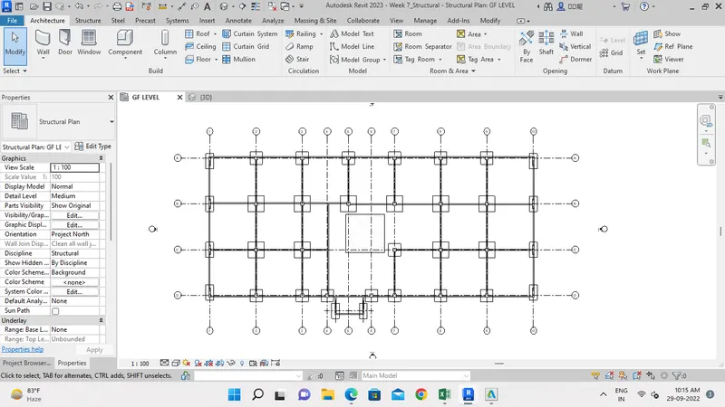
Step 5:-
- Copy the beam connection to all floors.
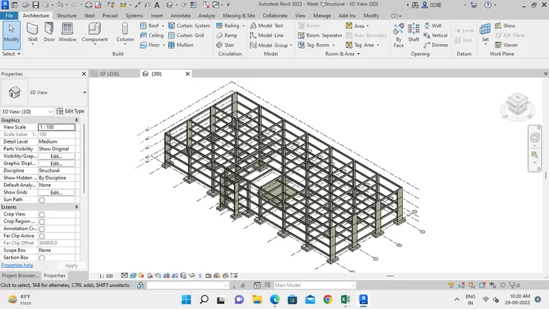
Step 6:-
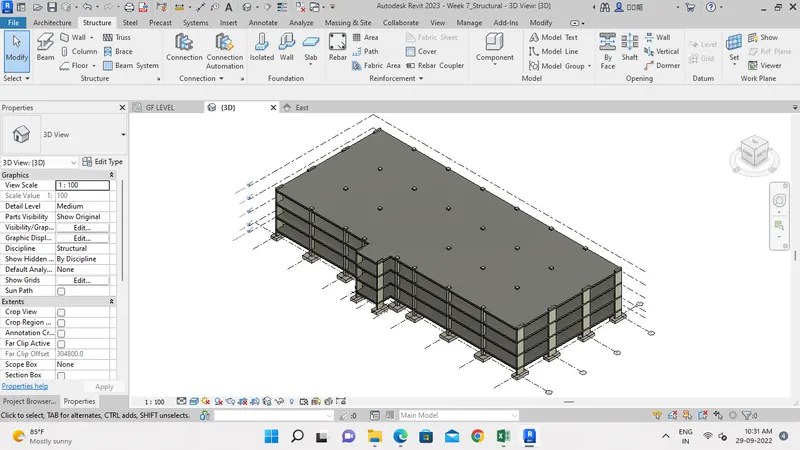
- In Structure tab, select Floor tool and duplicate the slab then change thickness to 200mm.
- Draw the boundary of Floor slab at Ground floor level.
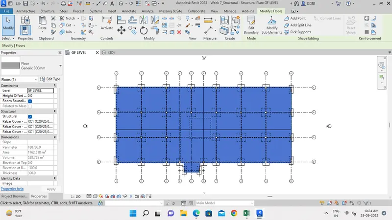
- Copy the Floor slab to all Floor levels.
Step 7:-
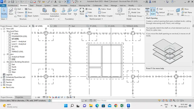
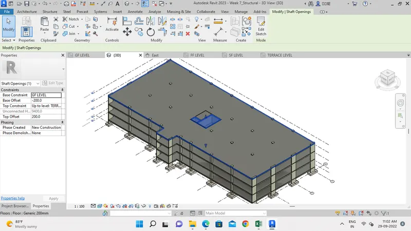
- In Structure tab, select Shaft tool and draw the boundary of Elevator and Staircase.
- Then fix Top constraint and Bottom constraint.
Result:-
- Structural components like Foundation, Columns, Beams connected to Columns, Roof and Floor elements and Shaft openings created successfully using Structure tab.
4) Using the architectural model, include the following components based on the type of structure selected
a. Wall Layout with appropriate material and finishing
b. Exterior façade with fancy finish
c. Interior partition walls to size rooms
d. Components to add details to a room ( Desk, Chair, Lighting, Plumbing fixtures)
e. Add components such as stairs Elevators
f. Have at-least one side of the building with curtain walls and glass panels
g. Include interior and exterior lighting fixtures
h. Place proper topographic components from outside ( Trees, Parking, Plants) to add details to the model
Aim:-
To place Architectural components such as Walls, Furnitures, Glass panels and Lighting fixtures to the Architectural model.
Introduction:-
- Architectural components gives the aesthetic appearance and covering to the Building model.
Procedure:-
Step 1:-
- In File tab, select new tab to Create a Architetural Template as shown below.
- In Mange Tab, select Manage link and link Structural model.
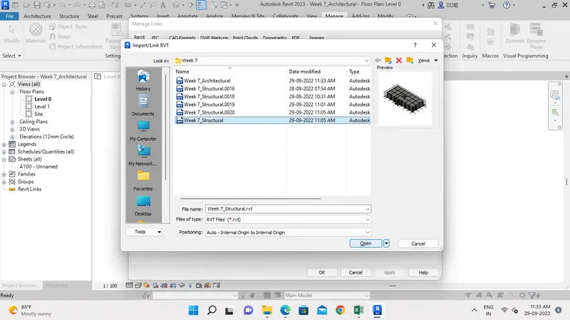
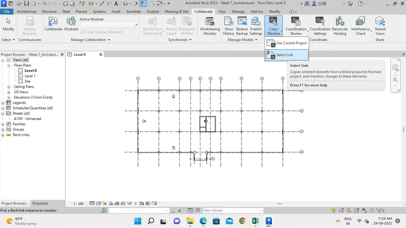
- Then Copy the Grids and Level from Structural model using Copy/Monitor tool.
Step 2:-
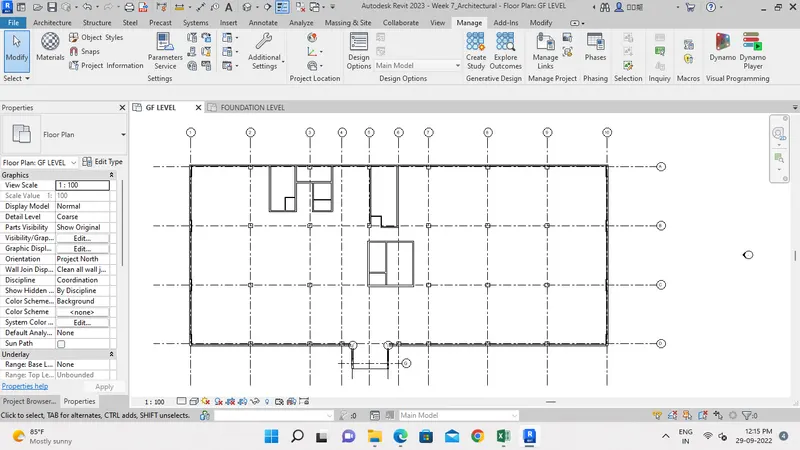
- Click the Architecture wall components to the model using Architectural Tab.
- Select the Wall-Ext_215Bwk type wall and place the wall at appropriate location as shown below.
Step 3:-
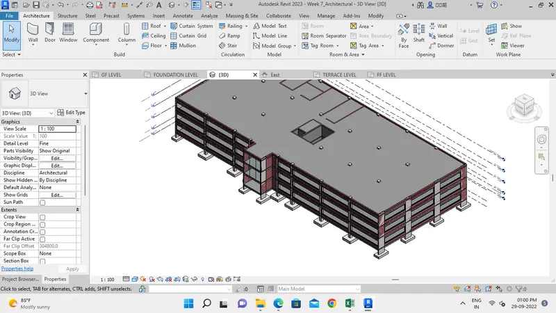
- Place the Exterior glass window to building model using Architectural Tab.
- And Place Curtain wall at Portigo area as shown below.
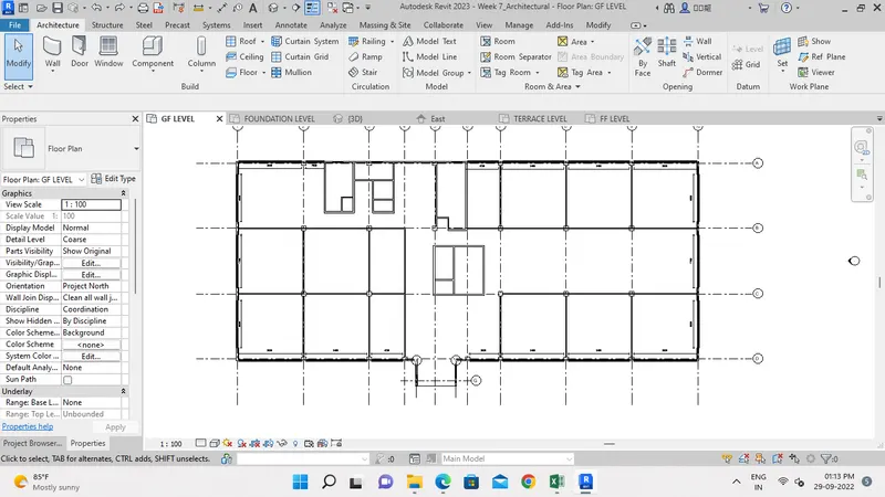
Step 4:-
- Place the Interior wall to the interior space for creating the interior rooms from the Architecture Tab.
Step 5:-
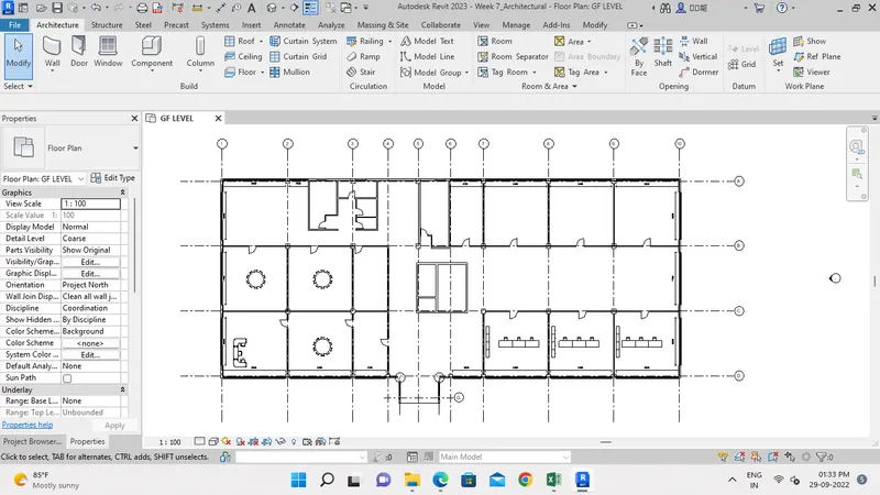
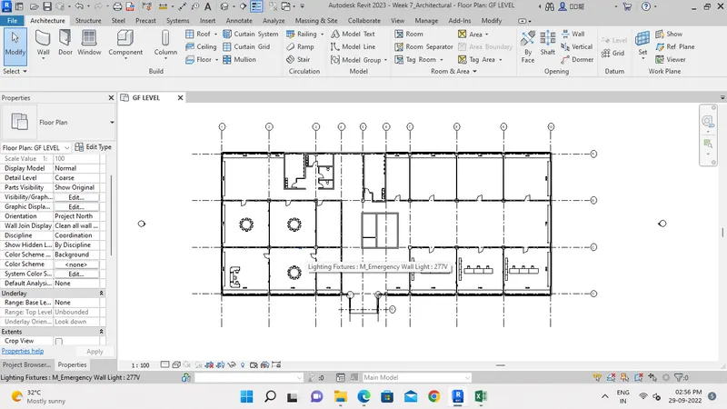
- Place the Furnitures like doors, Chairs and Desk to the model from the Insert Tab.
Step 6:-
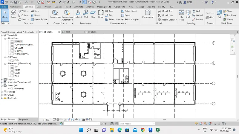
- Place Staircase from Architecture Tab.
- To Place elevator, First load family from Insert Tab.
- And place the Elevator at location.
Step 7:-
- To place Topographic componets, In Massing & Site Tab select Topographic Components.
- And Place the component at appropriate location.
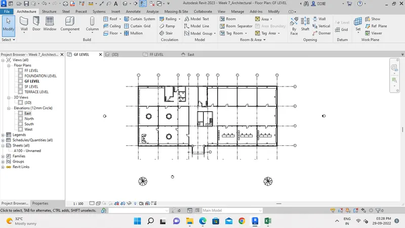
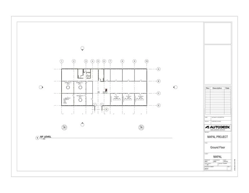
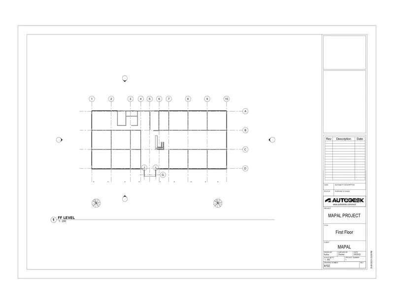
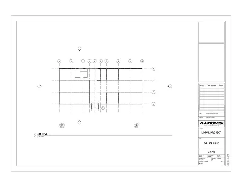
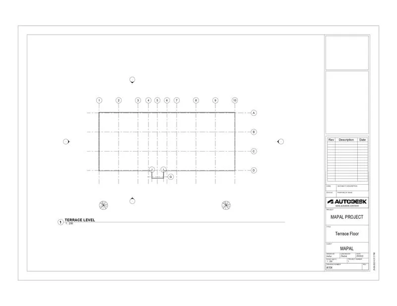
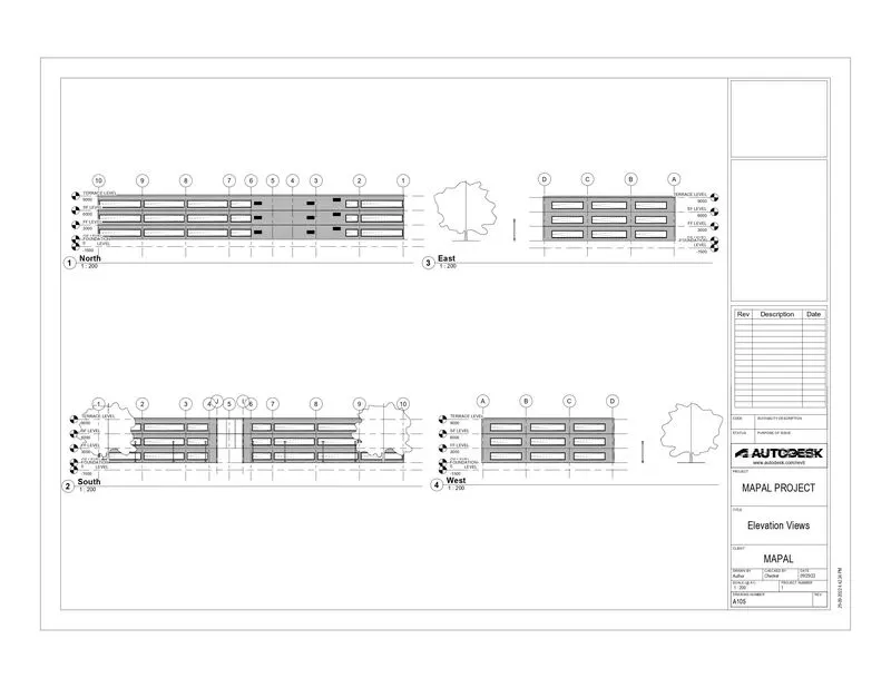
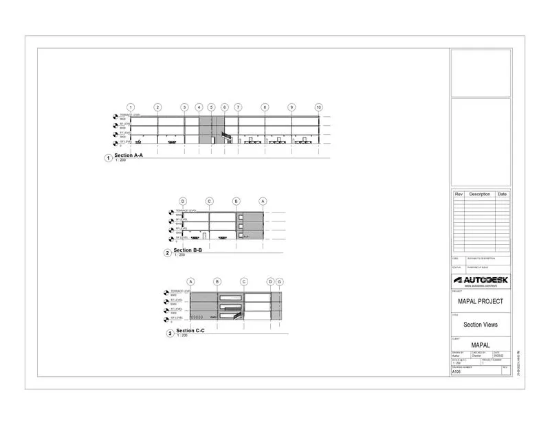
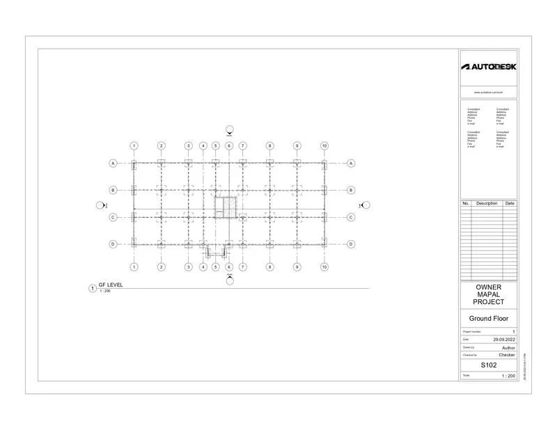
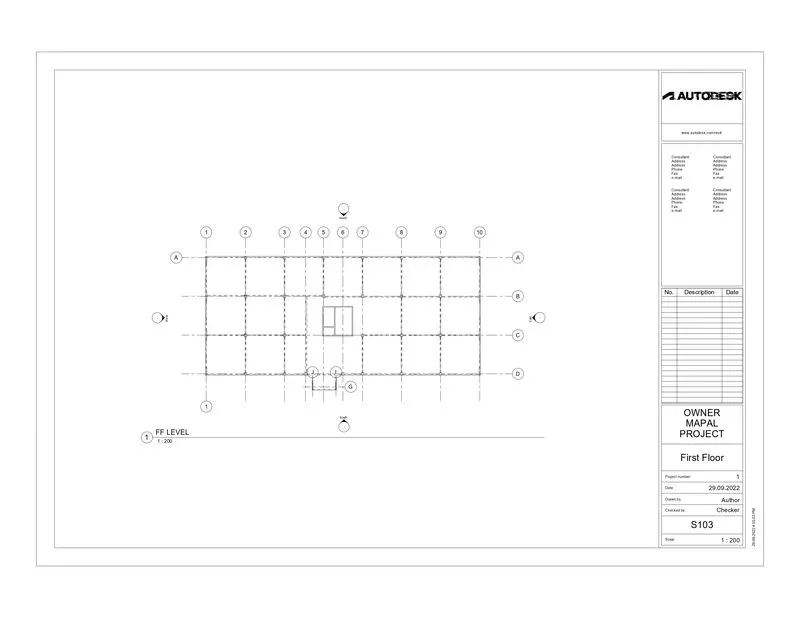
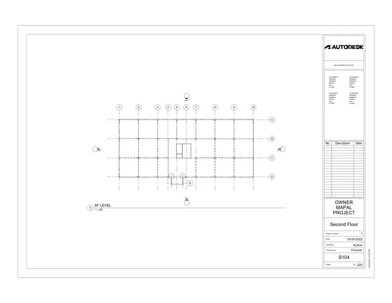
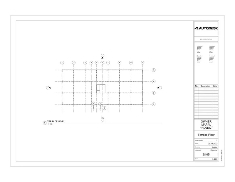
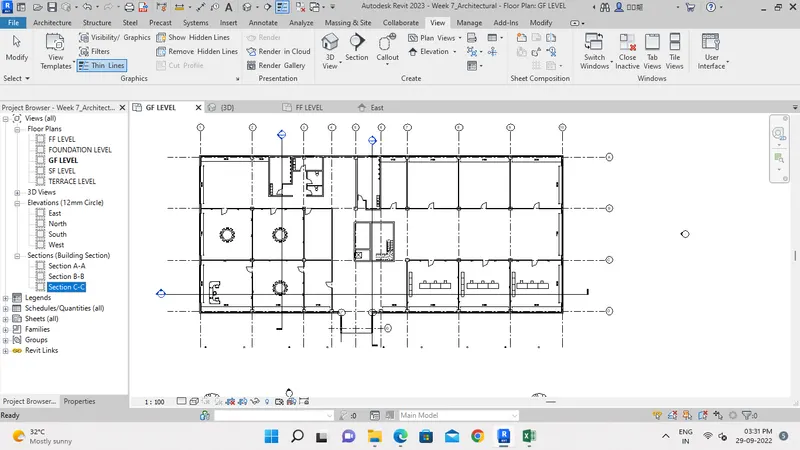
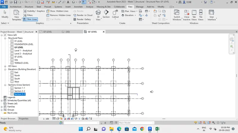
5) Provide a set of drawings in an architectural and structural model to list the following details with categories and appropriate sheet templates included
a. Floor Plans with Annotations
b. Elevations
c. Sections
Architectural Model:
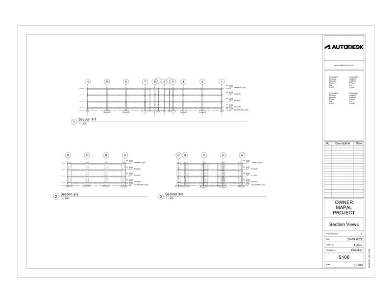
Structural Model:
6) Using the Rendering settings, Render images of the 3D model produced and include the rendered images to the drawing sheets
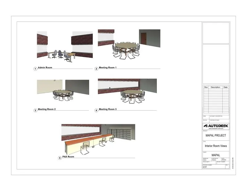
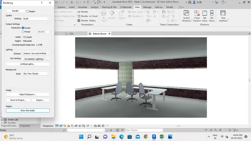
a. Rendering from interior rooms
b. Rendering from out showing topographic features
c. Rendering through structural framing
Aim:-
To create Rendering Views of Interior rooms, Topographic features and Structural framing.
Introduction:-
- Rendering view gives the reality view of the building model.
Procedure:-
Step 1:-
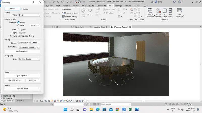
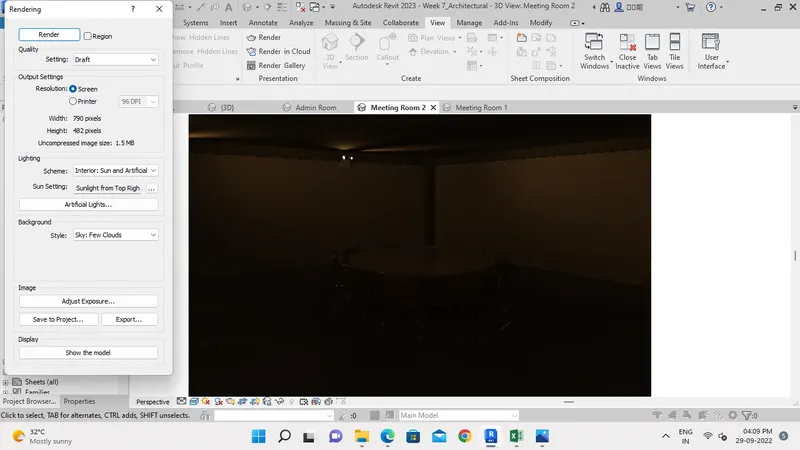
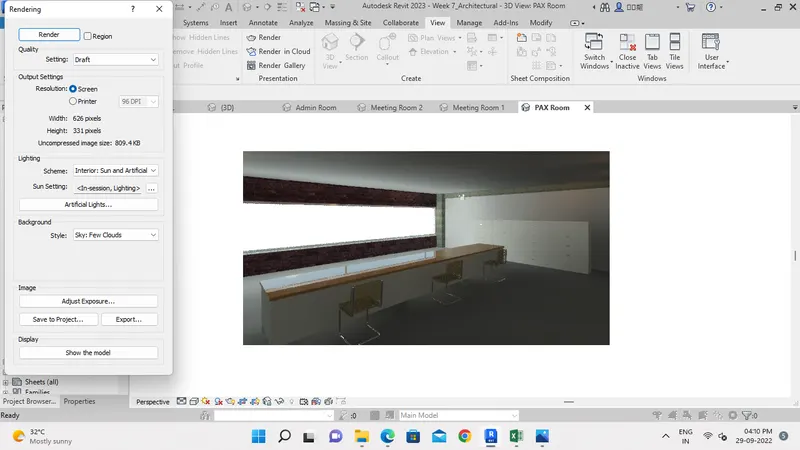
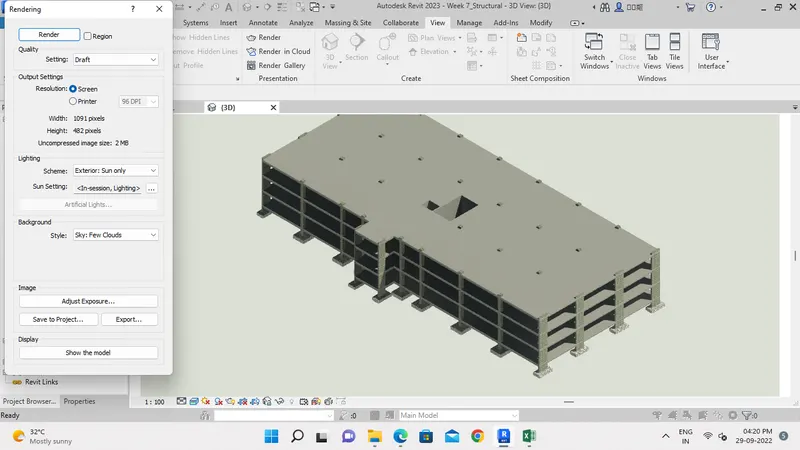
- Open Interior Room Views and render as follow.
- In View Tab, Select Render option.
- A pop-up window opens and select scheme of Lighting.
- Click the render, then rendered view will appears in the window.
Step 2:-
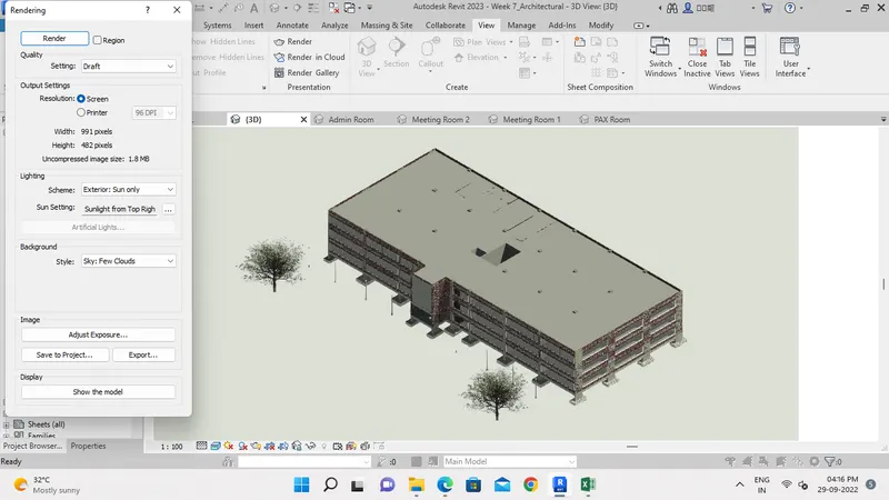
- As did for Interior Rooms, repeat the same procedure for Exterior topograhy with varioue lighting scheme.
Step 3:-
- Open Structural model and render the model externally and internally.
Result:-
- Successfully Rendered the Interior Rooms, STructural Model and External Topographic features.
7) Print the set of drawing sheets created and submit the drawings from the architecture and structure model
Aim:-
Tp print the set of drawing sheets created and submit the drawings from the architecture and structure model.
Procedure:-
Step 1:-
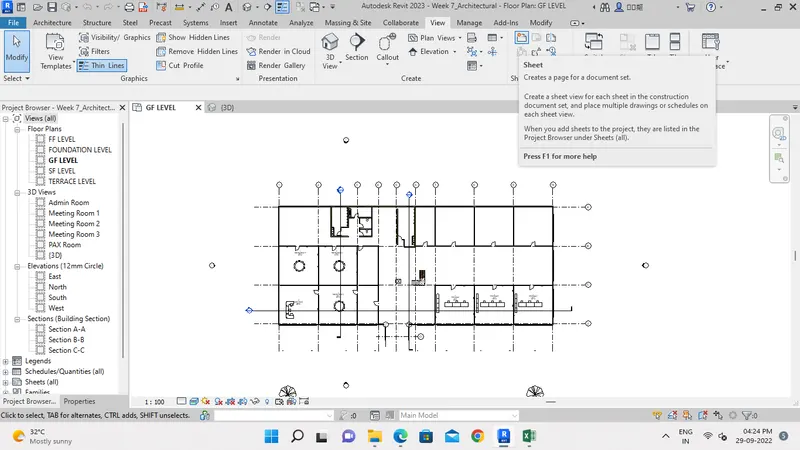
- Open the Architectural model and in View tab select sheet tool as shown below.
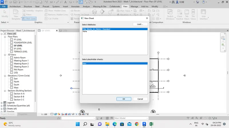
- A pop-up window opens, in that select Sheet size and click OK.
Step 2:-
- Enter the Project information and rename the Sheets.
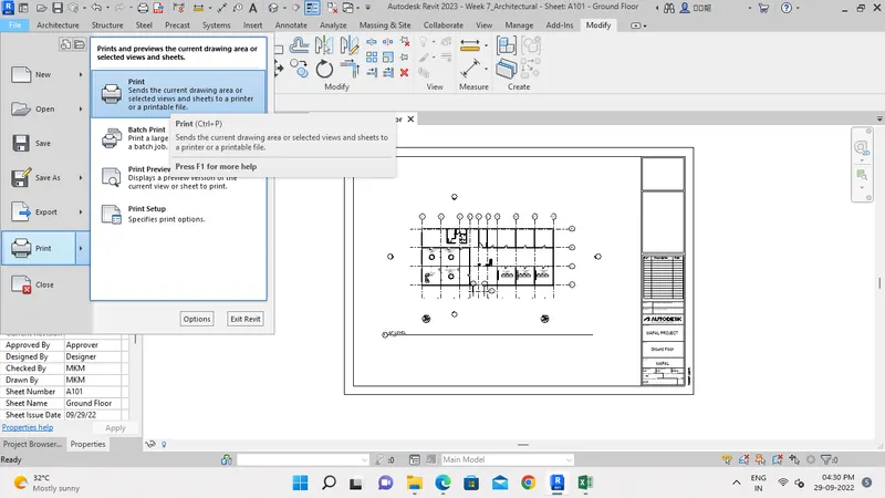
- Then drag the Floor plan to the sheet and scale it.
- In File Tab, select the print option and print the file.
Step 3:-
- Similarly print the all sheets for Architecture and Structure Model.
Result:-
- Printing of Drawing sheets created was done successfully.