Introduction to REVIT concepts
1. Aim: To create the new poroject and name the project appropriately.
Introduction: To create the new project and name the project appropriately by using Revit.
Procedure:
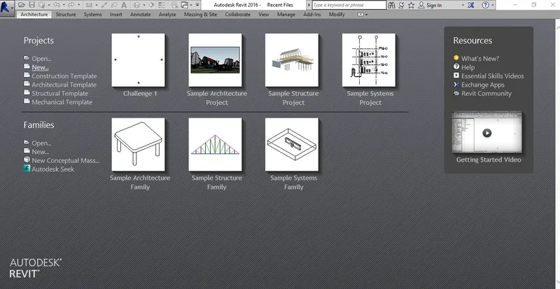
- First Open the revit software and is opened as below.
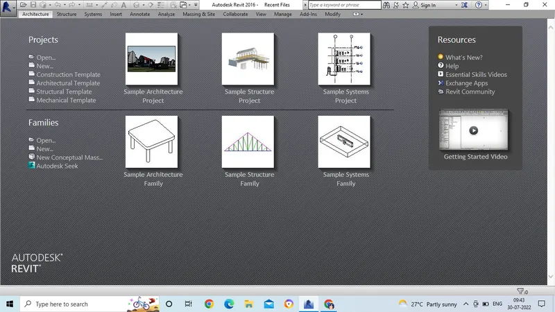
- Then after opening the revit, then click on the icon button "New".
- From the new file you have to select the template option.
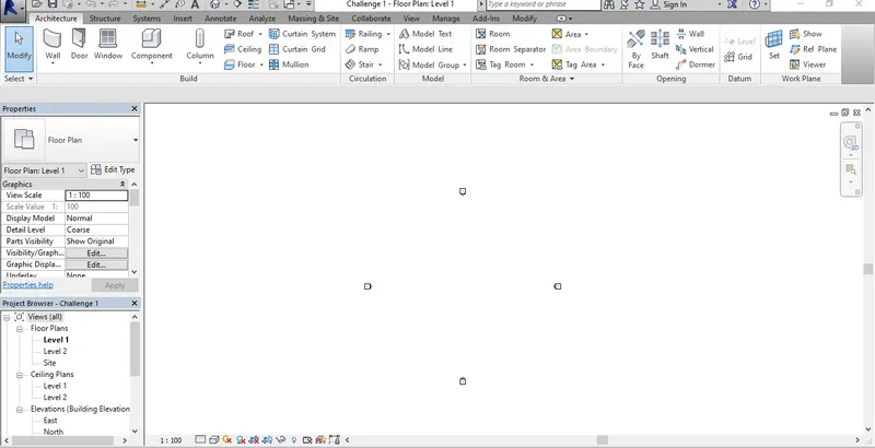
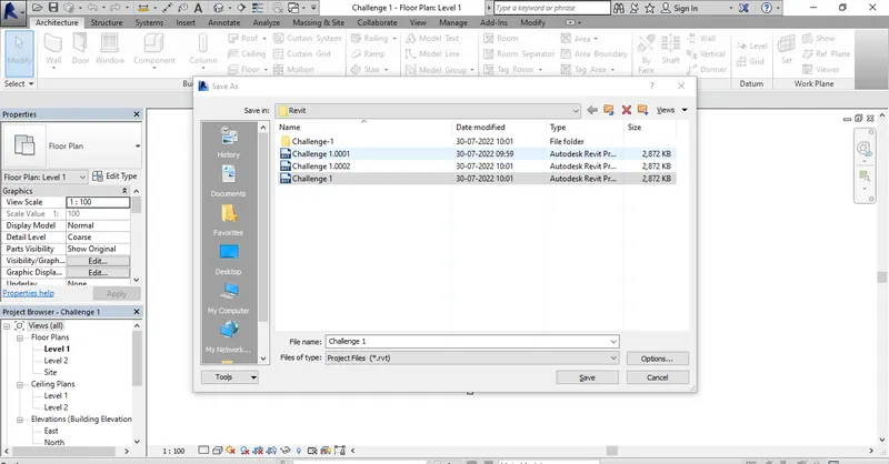
- After opening the file, hyou have to save the file from file menu option as save.
- Then save the file in the required location.
Result:
2. Aim: To save the new file and close and open the using icon in the tool bar.
Introduction: To save the new file and close and open the using icon in the tool bar in the Revit.
Procedure:
- Open the file option in the revit to save the file.
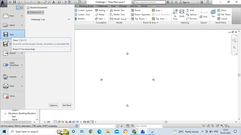
- In the file option there is an another option as close.
- Then click "Close" to close the file.
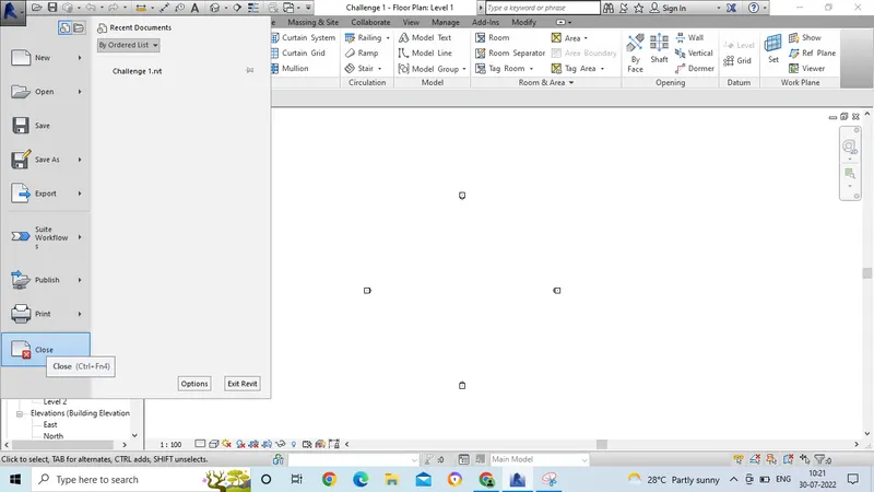
- Then once again open the file by using file menu option.
Result:
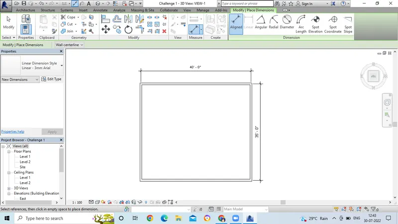
3. Aim: To create a rectangular wall layout of about 40'-0" X 35'-0".
Introduction: To create a rectangular wall layout of about 40'-0" X 35'-0" from the architecture /structure toolbar.
Procedure:
- To create the rectangular wall we have to open the architecture tab in the Menu bar.
- Then from that, we have to take the wall option from the given options.
- After taking wall, we have to take either line or rectangle to draw the line.
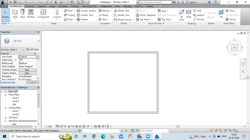
- After drawing the wall, we have to mention the dimensions for the wall outer lines.
- For that, we have to go to modify command and in that there are 2 options for dimensioning.
- Either by using Aligned option or linear option we can give the dimensions to the wall.
-
Result:
4. Aim: To annotate the tool bar using aligned dimension to add dimension in the layout.
Introduction: To give the dimensions by using aligned dimensions in the tool bar.
Procedure:
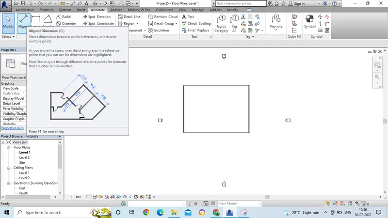
- After drawing the object, we have to mention the dimensions.
- For that, we have to go to modify command and in that there are 2 options for dimensioning.
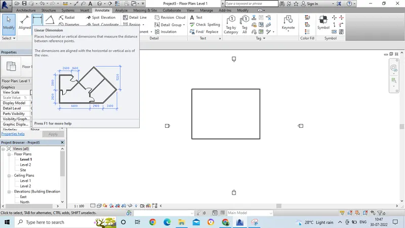
- Either by using Aligned option or linear option we can give the dimensions to the wall.
- And also by taking linear dimensions also we can give the dimensions as in the given attachment.
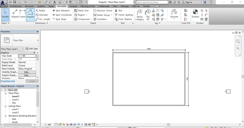
- After using Aligned and linear dimensions, dimensions are mentioned to the wall as below.
Result:
5. Aim: To use the property browser for different wall types.
Introduction: To use the property browser to switch the different wall types
Procedure:
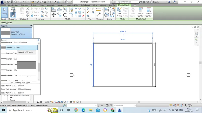
- To create the different types of wall sizes we have to take properties browser.
- In the Properties browser, when we select the wall there we can see the properties of the wall.
- From the wall we can take the wall sizes and all the properties and we can apply to the wall.
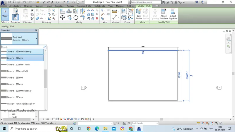
- In the same way, we can apply the different properties for the wall in properties bar.
Result:
6. Aim: To create the 3D view from the view toolbar and save the view with the appropriate name.
Introduction: To create the 3D view from the view toolbar and save the view with the appropriate name.
Procedure:
- We have to convert the wall into 3D view wall.
- Now we have to go for the View option, there we can see the 3D option.
- From the 3D options we can select the default 3D view.
- Then it will take to the custom view.
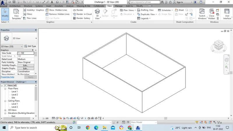
- Now after converting into custom view, by using view cube we can change the direction of the view.
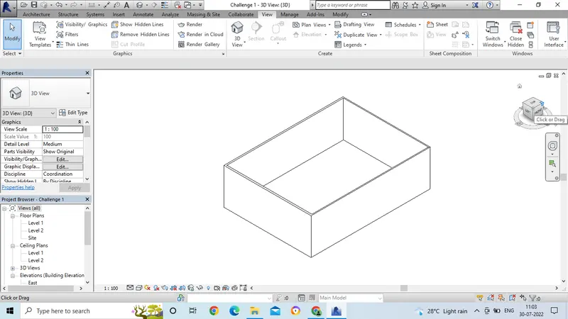
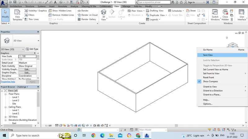
- Now, click on the iew cube right button.
- Then we will get the properties option.
- From the properties option we can save the view.
Result:
7. Aim: To create a 3D model using view cube.
Introduction: To create a 3D model using view cube in Orbit/Pan through the model layout created.
Procedure:
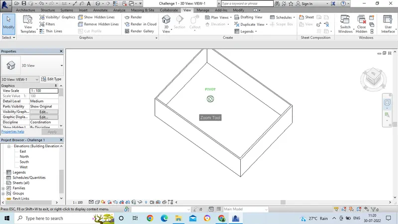
- In the user interface option, there we can get the navigation bar.
- We can click on the bar, then we will get the navigation bar icon.
-
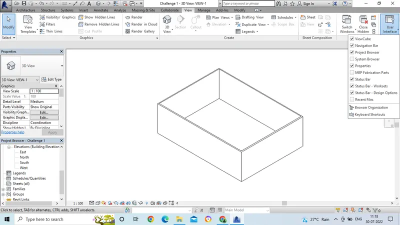
- In the Navigation bar, we can select the options and we can apply to the drawing.
- We can use zoom, pan all the options for the drawing.
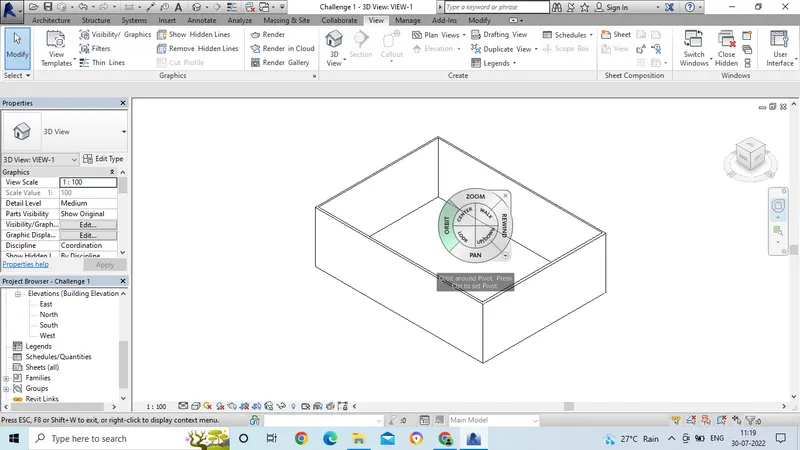
Result:
- By taking the orbit tool option.
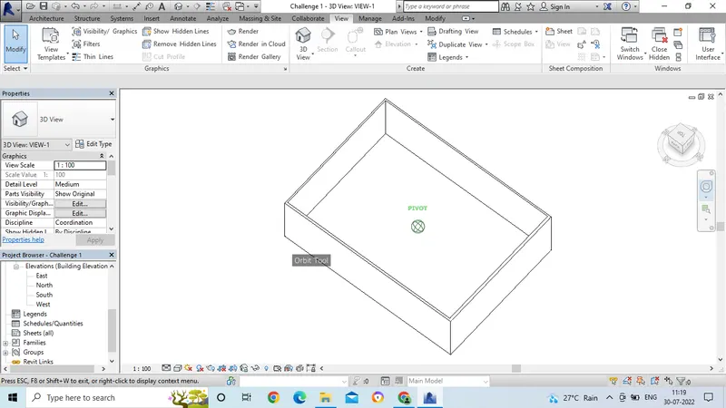
- By taking the pan tool option.
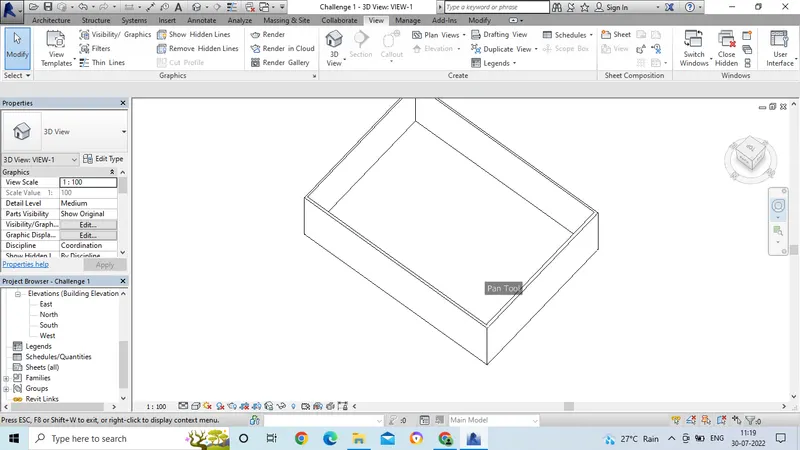
- By taking zoom tool option.
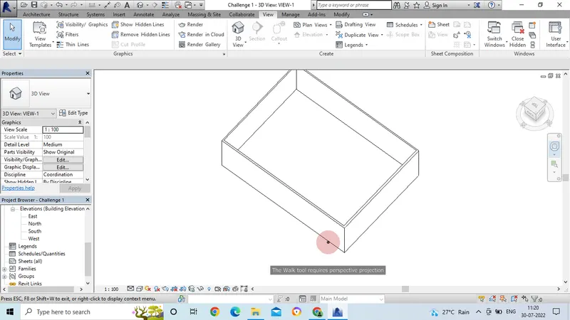
- By taking walk tool option.
8. Aim: To use the visibility settings option for the drawing.
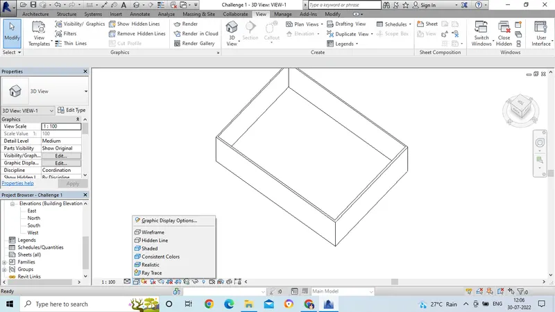
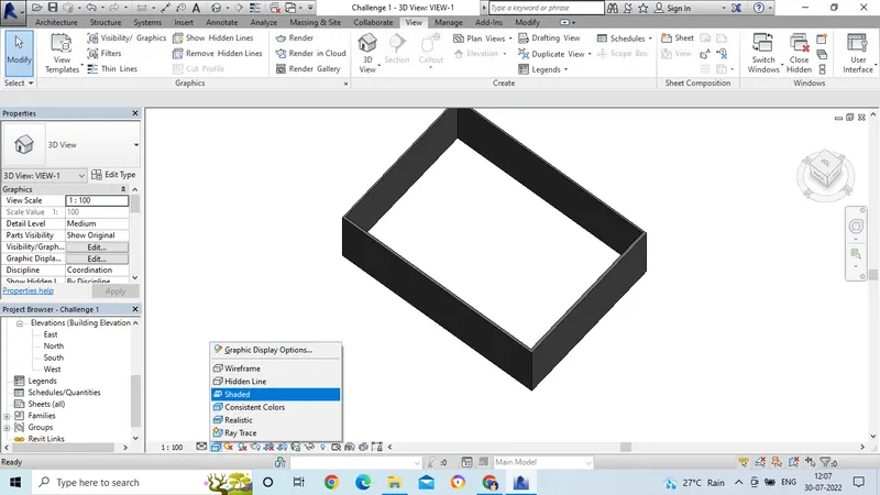
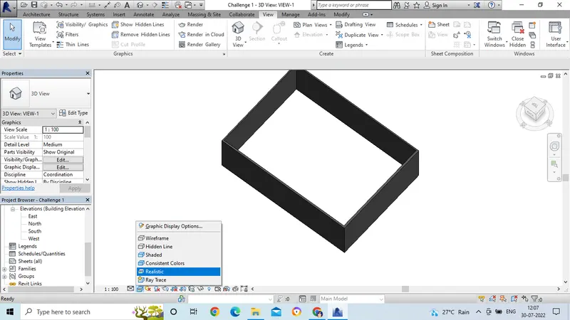
Introduction: To use the visibility settings option below to switch model to shaded, realistic, hidden lines options.
Procedure:
- In the below page we can find the visibility option to switch the models.
- If we take the shaded region, the image will get in the shaded region.
- If we take the realstic option we can get the image in the real view.
Result:
- In the shaded region,
- In the realistic view,
-
9. Aim: To create the sun path on and off to view shadings in the layout created.
Introduction: To create the sun path on and off to view shadings in the layout created by using Autocad.
Procedure:
- In the below page, we can see the sun path icon over there.
- If we click in that, we will get the options to sun path on and off to view shadings.
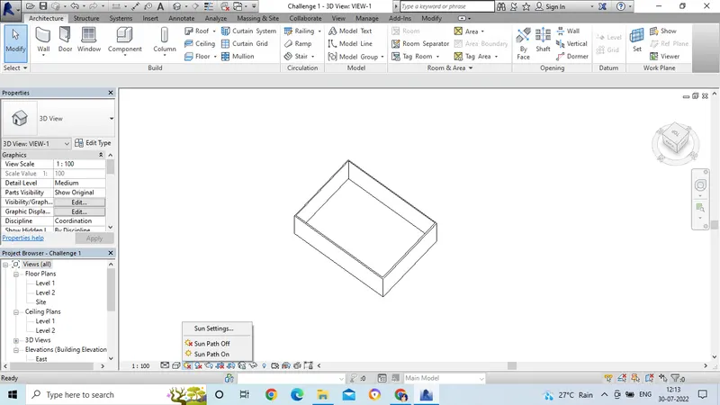
- If we click on the sun shade on, Then we can see the sun rays path coming as in the below attachment.
- We can see the on and off options for the sun shade.
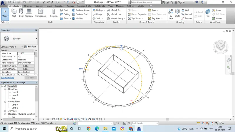
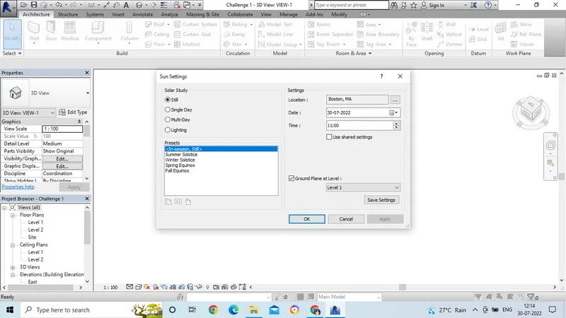
- And also, we can find the settings options in the sun rays path.
- There we can change the settings as per our requirement.
Result:
10. Aim: To create the project name, Project issue date and project settings in the toolbar.
Introduction: To create the project name, Project issue date and project settings in the toolbar and to choose according to our convenience.
Procedure:
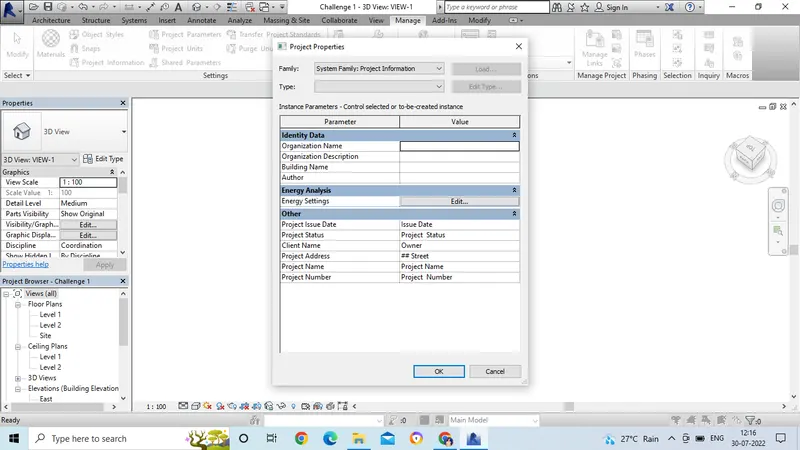
- To create the project name, tittle and settings, we have to go to manage tool bar.
- In the manage tool bar, there we can find the project information icon.
- If we click on the project information icon, we can get the details icon bar.
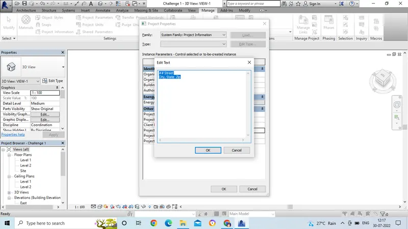
- In the address icon, if we click 3 dots we will get the detailed space page to enter full address.
Result:
11. Aim: To analyze the toolbar used in Revit and beneficial for design and modeling.
Introduction: To analyze the toolbar used in Revit and beneficial for design and modeling in Revit.
Procedure:
- It can be used to structural analyse of the building.
- It has various options that analyze the process.
- Boundary condition option defines boundaries and area conditions in the analytical model.
- Then load option applies point, load and area load to the model.
- In the load cases can add load in the analytical model.
- Load combination can add or edit the load combination for the analytical model.
- It defines it's name, type and usage of the analytical model.
Result:
12. Aim: To create the links that are used in the revit in the model.
Introduction: To create the links that are used in the revit in the model.
Procedure:
- Linking models is primarily intended for linking separate buildings, such as those that compose a campus.
- We can link Architectural models, structural models, and MEP models.
- When we link a model in to the project, Revit opens the linked model and keeps the memory.
- The more links contains, the longer it can take time to open.
- Linked models are listed in the revit links in the project browser.
Result:
13. Aim: To know about the Collaborate tab in the Revit.
Introduction:To know about the Collaborate tab in the Revit and how it supports in modeling and its efficiency.
Procedure:
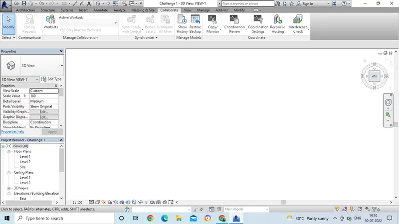
- Collaboration tab in revit enables the work sharing.
- through this can work together in a smae revit model.
- So that we need to use collaborate option in revit.
Collborate tab helps in
- Work together : For work sharing multiple revit models can link together allowing to work in context.
- Colud sharing : This sharing can work with multiple people with multiple locations with same geographical locations.
- Work sharing : By enabling this involves a master project model known as central model from existing model.
- Central model: It stores the current model information for all works and elements in the project and act as the point for all the changes made to the model.
- They can edit locally with all the work space.
- And also it supports the modeling.
- It allows the key design features.
- Finally it allows the parameters as the design to make the model changes quick and easy.
Result: