Introduction to REVIT concepts
1) AIM: To create a new project and to name it appropriately.
PROCEDURE:
- Go to desktop and select the below shown icon.
- Once the icon the selected then the below shown dialogue box will appear.
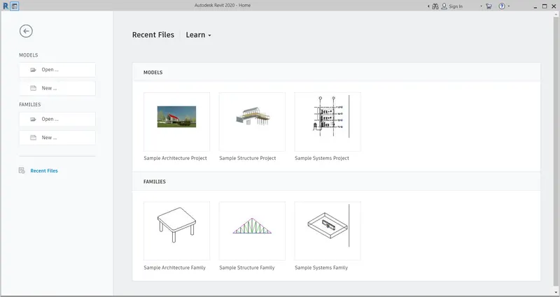
- Here click NEW option which is present in upper left hand side.
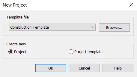
- The above dialogue option will appear.
- Here select the template file and type of project and click OK button.
- Then the drawing sheet will appear with different options to draw and with certain levels.
- Once the drawing sheet is opened now we have to save the drawing.
- Now go to file menu and select the save option.
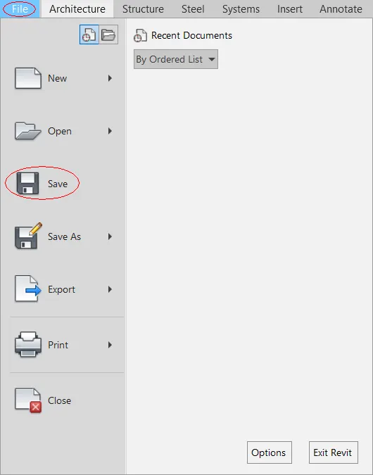
- Now after selecting the save option the another dialogue option will appear.
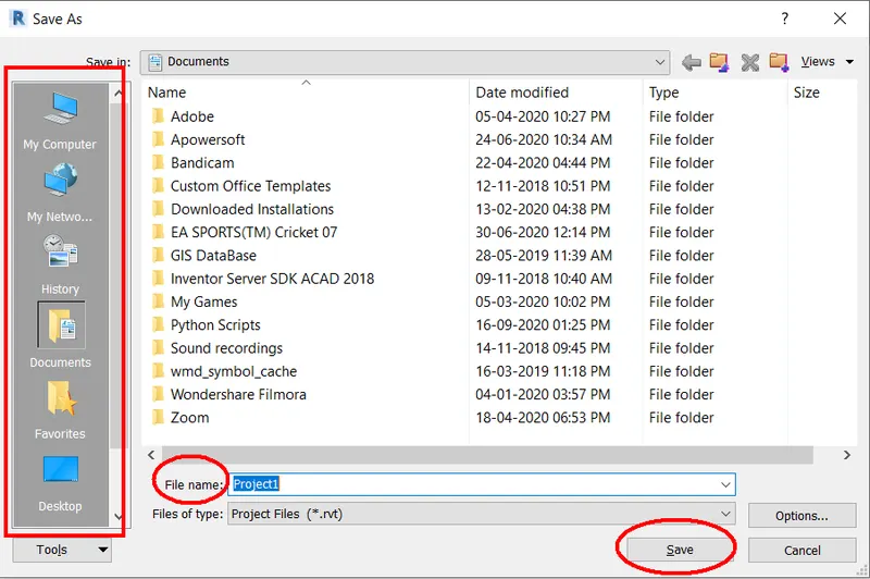
- Here there are several options.
- Select the place where the drawing has to be saved in. Using save in option.
- After selecting the place where the drawing has to be saved then give the name of drawing so that it can be easily identified.
- The naming is given in File name option.
- Once the file naming is done then select the save option then the drawing will be saved.
- Then the same name appears in the drawing sheet toolbar.
- By the above mentioned steps any drawing can be saved.
- These are the major steps that has to be followed as soon as you open the Revit software.
2) AIM: To save the new project file. Close and open using icons from file toolbar
PROCEDURE:
- Go to desktop and select the below shown icon.
- Once the icon the selected then the below shown dialogue box will appear.
- Here click NEW option which is present in upper left hand side.
- The above dialogue option will appear.
- Here select the template file and type of project and click OK button.
- Then the drawing sheet will appear with different options to draw and with certain levels.
- Once the drawing sheet is opened now we have to save the drawing.
- Now go to file menu and select the save option.
- Now after selecting the save option the another dialogue option will appear.
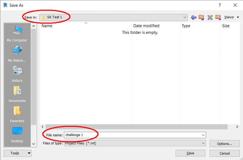
- Here i have selected the place where the drawing has to be saved and also given the name for the drawing.
- After doing all the required selections now click save option and the drawing will be saved in alotted place.
- Once the drawing is saved now we have to close the drawing using toolbar.
- Now again go to File menu and the same dialogue box will open.
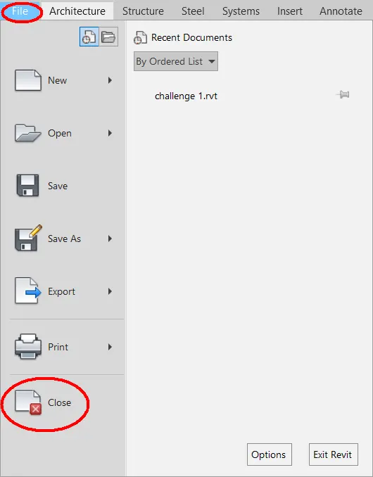
- Once the dialoge box is opened the this time we have to select the CLOSE option to close the drawing.
- Now we will be headed back to the same main menu which we previously got while opening the revit.
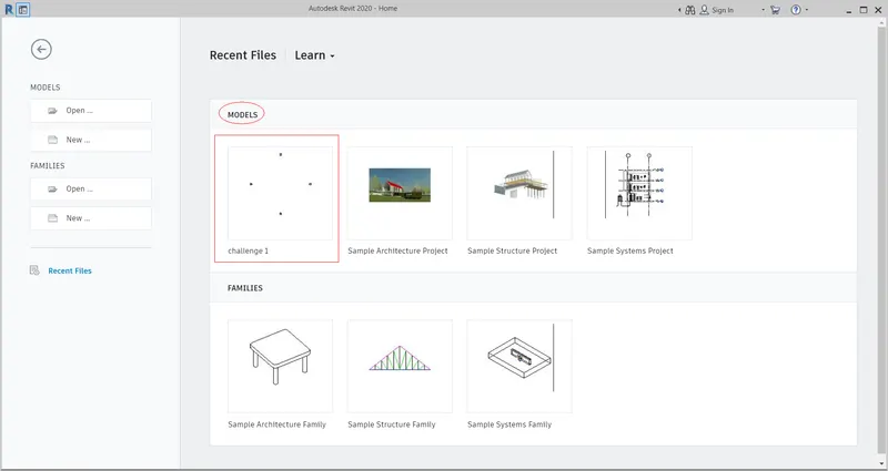
- Here go to MODELS and there will be the drawing that we have recently used and saved
- Go and select the drawing and the previously saved drawing will appear.
- By this above method the drawing can be closed and reopened using the toolbar.
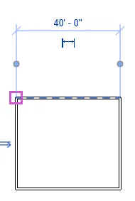
3) AIM: To from the architecture/ structure toolbar familiarize with options to draw a wall. Create a rectangular layout of walls of about 40’-0” X 35’-0”.
PROCEDURE:
- Go to desktop and select the below shown icon.
- Once the icon the selected then the below shown dialogue box will appear.
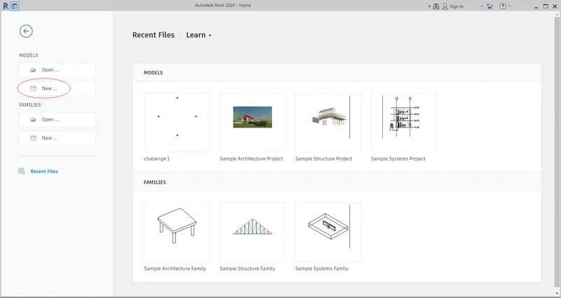
- Here click NEW option which is present in upper left hand side.
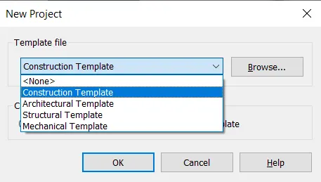
- The above dialogue option will appear.
- Here select the template file and type of project and click OK button.
- Then the drawing sheet will appear with different options to draw and with certain levels.
- Once the drawing sheet is opened now we have to save the drawing.
- Save the drawing using the mentioned steps in previous question.
- Go to architectural toolbar and select wall there are two types of wall.
- Load bearing and Architectural wall select as wanted.
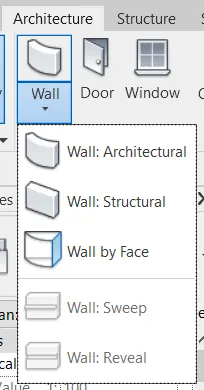
- Select the required type of wall and different options will appear in the toolbar.
- Using those options we can do several editings in wall and different shapes also.

- Here in draw option we can draw the wall in different shapes and size.
- Here we will choose ine option to draw a wall.
- Here we have to select the height of wall.
- Alignment of wall in Location line. Offset if any needed.
- After selecting all the dimensions and doing all the editings now draw the line as required.
- Click anywhere in the drawing sheet and take the curzer horizontally and type 45' the wall will be displayed as shown.
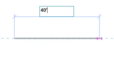
- Now take the cursor in 90degree and type the reading or length as mentioned.
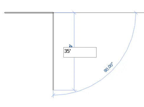
- Carry the same steps and complete the wall in four sides.
- After completing the wall will look as shown below.
- Either we can close the wall by giving the dimension or just by clicking the cursor in the starting point.
- By this way we can draw the wall for required height and width.
RESULT:
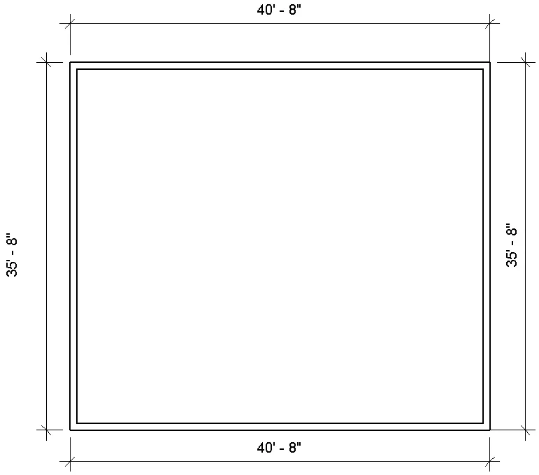
4) AIM: To from the Annotate toolbar use the aligned option to add dimensions to the layout.
PROCEDURE:
- Here we have to do the dimensioning so take the drawing that has been done in question 3.
- Go to Annotate tab and the below mentioned toolbar will appear.
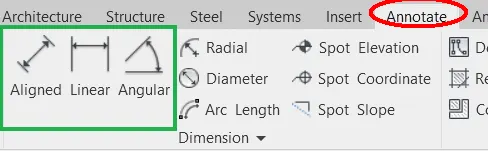
- Now here select the type of dimensioning you want.
- Here there are several options for dimensioning. Here we can do the dimensioning of radius, Diameter etc.
- Now here we are selecting the LINEAR dimensioning because the drawing is aligned linerally.
- Now go near drawing and click the start point of the dimension.
- Next click on the other side of the drawing which is in right angle.
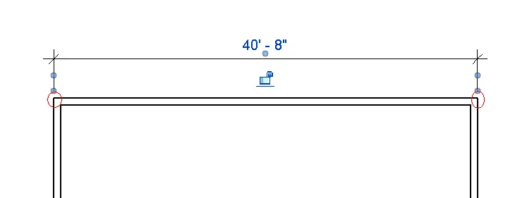
- After that take the curser in upward direction till the required height then place it.
- Cary the same steps for all the remaning side of the wall.
- Here we can use either Aligned or Linear dimensioning.
RESULT:
5) AIM: To use the properties browser to switch to different wall types.
PROCEDURE:
- Go to desktop and select the below shown icon.
- Once the icon the selected then the below shown dialogue box will appear.
- Here click NEW option which is present in upper left hand side.
- The above dialogue option will appear.
- Here select the template file and type of project and click OK button.
- Then the drawing sheet will appear with different options to draw and with certain levels.
- Once the drawing sheet is opened now we have to save the drawing.
- Save the drawing using the mentioned steps in previous question.
- Go to architectural toolbar and select wall there are two types of wall.
- Load bearing and Architectural wall select as wanted.
- Select the required type of wall and different options will appear in the toolbar.
- Using those options we can do several editings in wall and different shapes also.
- Here in draw option we can draw the wall in different shapes and size.
- Here we will choose ine option to draw a wall.
- Here we have to select the height of wall.
- Alignment of wall in Location line. Offset if any needed.
- After selecting all the dimensions and doing all the editings now draw the line as required.
- Click anywhere in the drawing sheet and take the curzer horizontally and type 45' the wall will be displayed as shown.
- Now take the cursor in 90degree and type the reading or length as mentioned.
- Carry the same steps and complete the wall in four sides.
- After completing the wall will look as shown below.
- Either we can close the wall by giving the dimension or just by clicking the cursor in the starting point.
- By this way we can draw the wall for required height and width.
- Here we have to switch the wall using property browser. The property browser is shown below
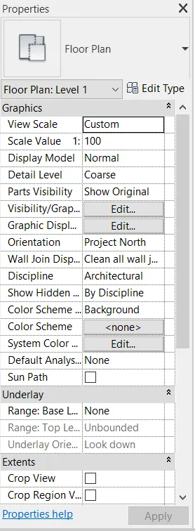
- First selelct the wall of which you want to change the properties.

- After selecting the wall the property browser will show the following items.
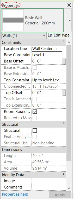
- This shows the type of wall and thickness and all the other details.
- Now we can change the wall type by selecting the down arrow in the basic wall section.
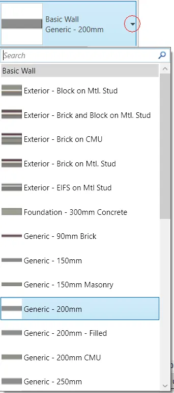
- Here we will get number of varieties where we can select the required type of wall.
- Select anyone which is neccessary.
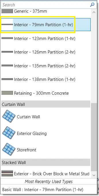
- Here i have selected the required wall with certaing thickness.
- The changes can be seen in naked eyes in the drawing. As shown below.

- Do the same steps for all the other wall which ever is required.
RESULT:
6) AIM: To create a 3D view from the view toolbar and save the view with the appropriate name.
PROCEDURE:
- Go to desktop and select the below shown icon.
- Once the icon the selected then the below shown dialogue box will appear.
- Here click NEW option which is present in upper left hand side.
- The above dialogue option will appear.
- Here select the template file and type of project and click OK button.
- Then the drawing sheet will appear with different options to draw and with certain levels.
- Once the drawing sheet is opened now we have to save the drawing.
- Save the drawing using the mentioned steps in previous question.
- Go to architectural toolbar and select wall there are two types of wall.
- Load bearing and Architectural wall select as wanted.
- Select the required type of wall and different options will appear in the toolbar.
- Using those options we can do several editings in wall and different shapes also.
- Here in draw option we can draw the wall in different shapes and size.
- Here we will choose ine option to draw a wall.
- Here we have to select the height of wall.
- Alignment of wall in Location line. Offset if any needed.
- After selecting all the dimensions and doing all the editings now draw the line as required.
- Click anywhere in the drawing sheet and take the curzer horizontally and type 45' the wall will be displayed as shown.
- Now take the cursor in 90degree and type the reading or length as mentioned.
- Carry the same steps and complete the wall in four sides.
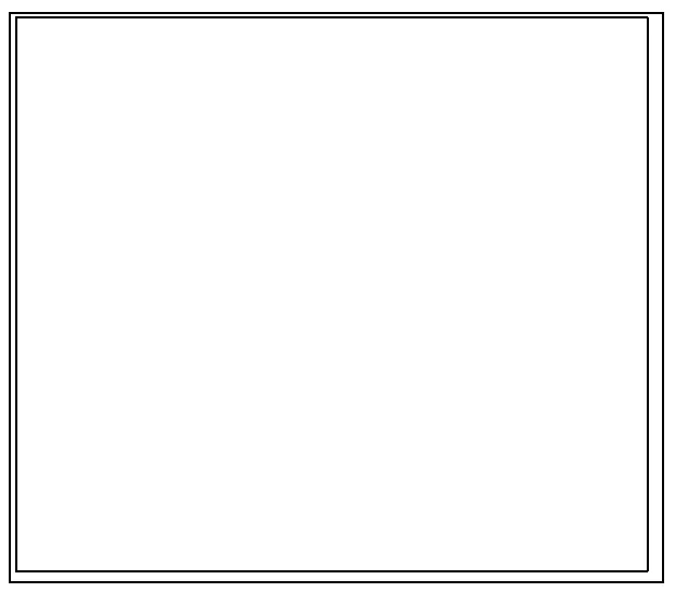
- After completing the wall will look as shown below.
- Either we can close the wall by giving the dimension or just by clicking the cursor in the starting point.
- By this way draw the wall for required height and width.
- Now we have to do a 3D view of this walls.
- In the top toolbar there is a 3D option as shown below

- Select the option that is highlighted and a another dialogue box will appear.
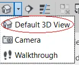
- Here select the Default 3D view and the drawing in the sheet will be appear in 3D view.
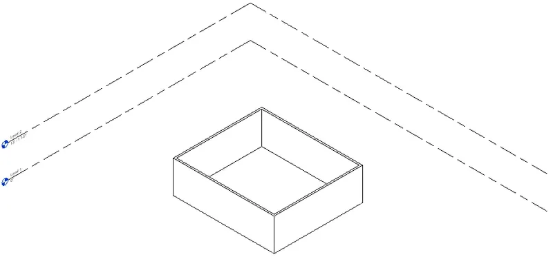
- Once the drawing is in 3D view now we have to save the different views.
- So to save the different views use the View cube where we can switch into different views.
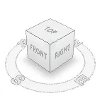
- By using this view cube we can switch into 14 different views.
- Now we have to save the view so take the curser to view cube and Right click above which view you want.
- A dialogue box will appear, There select the save view option another dialogue box will appear.
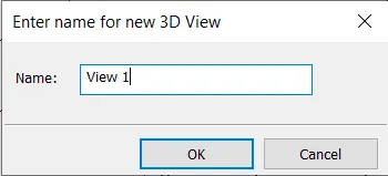
- Here give the name for the view and click OK.
- Follow the same steps to create several view and save it.
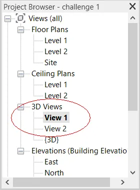
- The saved views can be seen in the Project Browser in 3D option.
- To change the view double click on the required view.
RESULT:

7) AIM: To navigate through the 3D model using the view cube. Orbit/pan through the model layout created
PROCEDURE:
- Go to desktop and select the below shown icon.
- Once the icon the selected then the below shown dialogue box will appear.
- Here click NEW option which is present in upper left hand side.
- The above dialogue option will appear.
- Here select the template file and type of project and click OK button.
- Then the drawing sheet will appear with different options to draw and with certain levels.
- Once the drawing sheet is opened now we have to save the drawing.
- Save the drawing using the mentioned steps in previous question.
- Go to architectural toolbar and select wall there are two types of wall.
- Load bearing and Architectural wall select as wanted.
- Select the required type of wall and different options will appear in the toolbar.
- Using those options we can do several editings in wall and different shapes also.
- Here in draw option we can draw the wall in different shapes and size.
- Here we will choose ine option to draw a wall.
- Here we have to select the height of wall.
- Alignment of wall in Location line. Offset if any needed.
- After selecting all the dimensions and doing all the editings now draw the line as required.
- Click anywhere in the drawing sheet and take the curzer horizontally and type 45' the wall will be displayed as shown.
- Now take the cursor in 90degree and type the reading or length as mentioned.
- Carry the same steps and complete the wall in four sides.
- After completing the wall will look as shown below.
- Either we can close the wall by giving the dimension or just by clicking the cursor in the starting point.
- By this way draw the wall for required height and width.
- Now we have to navigate the drawing using orbit and pan option to get that first go to View tab.

- The above options will appear in that select the user interface tab option.
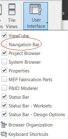
- The above options will appear there check wheather Navigation Bar is selected or not, If not then select it.
- After selecting check in screen wheather the below mentioned toolbar is visibile or not.
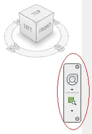
- In that select the Full navigation option then a box will appear with the mouse cursor.
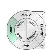
- Here select the required options and use it as needed.
- Select ORBIT option and don't leave the mouse button then rotate the mouse as needed in required direction.
- ORBIT helps us to check the drawing in all direction without any glitch.
- After orbit now select PAN option to move the drawing up, down, left or right.
- There are many other options that are used as required.
8) AIM: To use the visibility settings option below to switch model to shaded, realistic, hidden lines options.
PROCEDURE:
- Go to desktop and select the below shown icon.
- Once the icon the selected then the below shown dialogue box will appear.
- Here click NEW option which is present in upper left hand side.
- The above dialogue option will appear.
- Here select the template file and type of project and click OK button.
- Then the drawing sheet will appear with different options to draw and with certain levels.
- Once the drawing sheet is opened now we have to save the drawing.
- Save the drawing using the mentioned steps in previous question.
- Go to architectural toolbar and select wall there are two types of wall.
- Load bearing and Architectural wall select as wanted.
- Select the required type of wall and different options will appear in the toolbar.
- Using those options we can do several editings in wall and different shapes also.
- Here in draw option we can draw the wall in different shapes and size.
- Here we will choose ine option to draw a wall.
- Here we have to select the height of wall.
- Alignment of wall in Location line. Offset if any needed.
- After selecting all the dimensions and doing all the editings now draw the line as required.
- Click anywhere in the drawing sheet and take the curzer horizontally and type 45' the wall will be displayed as shown.
- Now take the cursor in 90degree and type the reading or length as mentioned.
- Carry the same steps and complete the wall in four sides.
- After completing the wall will look as shown below.
- Either we can close the wall by giving the dimension or just by clicking the cursor in the starting point.
- By this way draw the wall for required height and width.
- Now go to 3D view as mentioned in the above steps.
- There are many options in the bottom toolbar.
- Go to bottom toolbar and go to Visual style.
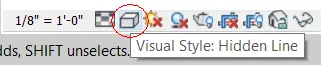
- Click the above shown icon and the dialogue list will appear.
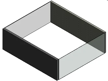
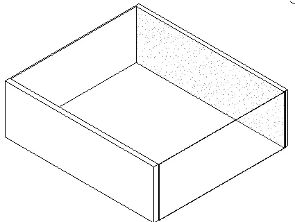
- There will be several options like wireframe, Hiddenline, shaded, Consistant colours, Realistic and Ray trace.
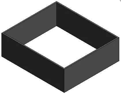
- In the above now we have to do shaded, realistic & hidden lines options.
- Click one by one and see the results.
RESULT:
SHADED:
REALISTIC:
HIDDEN LINE:
9) AIM: To turn the sun path on and off to view shadings in the layout created.
PROCEDURE:
- Go to desktop and select the below shown icon.
- Once the icon the selected then the below shown dialogue box will appear.
- Here click NEW option which is present in upper left hand side.
- The above dialogue option will appear.
- Here select the template file and type of project and click OK button.
- Then the drawing sheet will appear with different options to draw and with certain levels.
- Once the drawing sheet is opened now we have to save the drawing.
- Save the drawing using the mentioned steps in previous question.
- Go to architectural toolbar and select wall there are two types of wall.
- Load bearing and Architectural wall select as wanted.
- Select the required type of wall and different options will appear in the toolbar.
- Using those options we can do several editings in wall and different shapes also.
- Here in draw option we can draw the wall in different shapes and size.
- Here we will choose ine option to draw a wall.
- Here we have to select the height of wall.
- Alignment of wall in Location line. Offset if any needed.
- After selecting all the dimensions and doing all the editings now draw the line as required.
- Click anywhere in the drawing sheet and take the curzer horizontally and type 45' the wall will be displayed as shown.
- Now take the cursor in 90degree and type the reading or length as mentioned.
- Carry the same steps and complete the wall in four sides.
- After completing the wall will look as shown below.
- Either we can close the wall by giving the dimension or just by clicking the cursor in the starting point.
- By this way draw the wall for required height and width.
- Now go to 3D view as mentioned in the above steps.
- There are many options in the bottom toolbar.
- Go to bottom toolbar and go to SUN PATH.
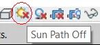
- Click the above shown icon and a dialogue box will appear.
- Which consist of SUUNPATH ON an SUNPATH OFF.
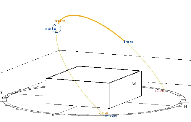
- Now select the SUNPATH ON option and see the changes in the drawing sheet.
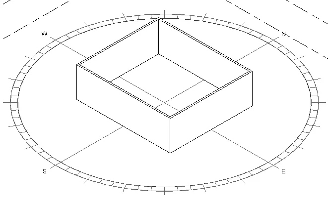
- The above outer circle will appear with the magnetic directions.
- There is also option to do the setting of the sun light.
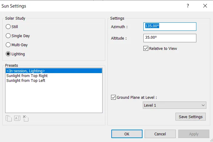
- Here we can set the solar study and altitude etc.
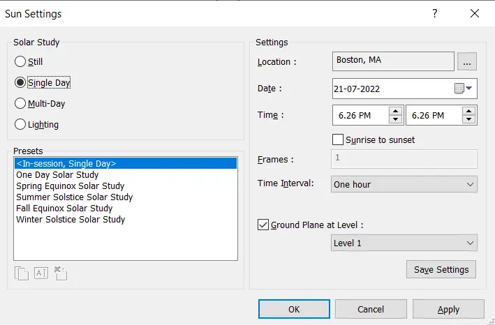
- Here if single day is selected then we can set the location date and timing etc.
- This has more options to set the currect settings.
- After all the settings we can see the sun placement as shown below.
- We can also off the sun path when required.
RESULT:
10) AIM: To use the Manage toolbar to enter project settings, project name, and project issue date as per convinence.
PROCEDURE:
- Go to desktop and select the below shown icon.
- Once the icon the selected then the below shown dialogue box will appear.
- Here click NEW option which is present in upper left hand side.
- The above dialogue option will appear.
- Here select the template file and type of project and click OK button.
- Then the drawing sheet will appear with different options to draw and with certain levels.
- Once the drawing sheet is opened now we have to save the drawing.
- Save the drawing using the mentioned steps in previous question.
- Go to architectural toolbar and select wall there are two types of wall.
- Load bearing and Architectural wall select as wanted.
- Select the required type of wall and different options will appear in the toolbar.
- Using those options we can do several editings in wall and different shapes also.
- Here in draw option we can draw the wall in different shapes and size.
- Here we will choose ine option to draw a wall.
- Here we have to select the height of wall.
- Alignment of wall in Location line. Offset if any needed.
- After selecting all the dimensions and doing all the editings now draw the line as required.
- Click anywhere in the drawing sheet and take the curzer horizontally and type 45' the wall will be displayed as shown.
- Now take the cursor in 90degree and type the reading or length as mentioned.
- Carry the same steps and complete the wall in four sides.
- After completing the wall will look as shown below.
- Either we can close the wall by giving the dimension or just by clicking the cursor in the starting point.
- By this way draw the wall for required height and width.
- To edit the project settings go to manage menu.
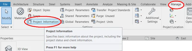
- The option toolbar will appear then go to Project information option.
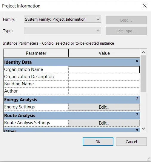
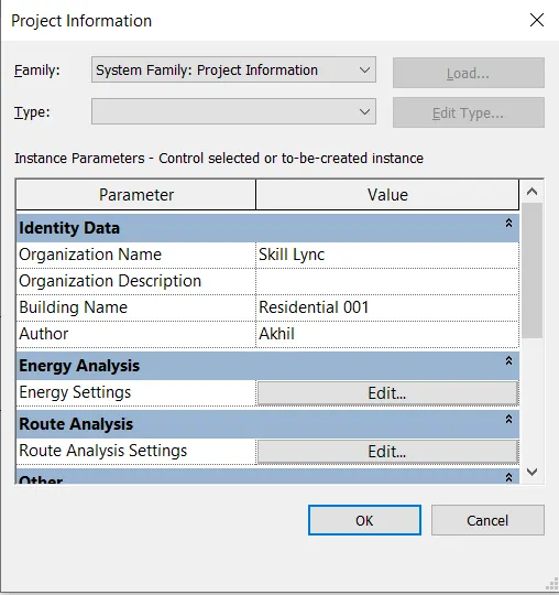
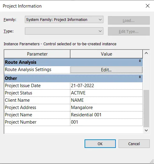
- Once we select the option the above dialogue box will appear.
- Here we edit the items that are mentioned tobe edited.
RESULT:
11) The analyze tool is used to analyze the structure by providing the loads. Here we can apply point, line and area loads. Different loads can be applied and the structural behavior can be seen. Below are the options that are provided in Analyze tool.

It is very beneficial to know the structural behavior. Here we can have load combination and we can lightly analyze the structure.
12) Linking models is primarily intended for linking separate buildings, such as those that compose a campus. You can link architectural models, structural models, and MEP models. When you link a model into a project, Revit opens the linked model and keeps it in memory. The more links a project contains, the longer it can take to open. Linked models are listed in the Revit Links branch of the Project Browser. You can convert linked Revit models to groups, and you can convert groups to linked Revit models. This dialog (Revit Links) is arranged in a tree structure with the parent nodes referring to separate files (the primary linked model), and the child nodes referring to instances (copies) of the model in the project. A relative path defines the position of a linked file in a working directory such as a project folder. Its position is defined by its relative location. An absolute path defines the location of a linked file on a disk or network drive. Changing the parent node affects all instances, while changing a child node affects only that instance. You can link models to more easily manage the individual parts or to improve performance when working on a large project.
13) The collaborate tab enables the work sharing it enables to work in the same revit drawing by people in different geography.
Revit provides several different ways to collaborate with team members who are using the software.
- Several multiple models can be linked together, allowing team members to work in a context.
- Through work sharing, users on same local area network (LAN) can work together in the same revit model.
- When collaboration needs to occur among users who are not in same geographic location, Revit cloud work sharing can be used.
- Revit connect offices that share a network but are not in the same geographic location.
- Revit cloud work sharing is a cloud based service that allows any revit user inside or outside a network to collaborate on a Revit model.
When there is a need to combine multiple models and files in a single project, shared coordinates can be used to establish the position of the files in relation to each other.
To establish a common coordinate position and then share that position between files, Acquire coordinates tool can be used.
It enables multi-user coauthoring or cloud Work sharing of Revit models. Teams stay connected in real time using the Communicator chat tool within models. Integrated with Autodesk BIM 360™ Team, Collaboration for Revit enables the entire project team to access shared building information models. Revit users subscribe to Collaboration for Revit, which includes BIM 360 Team.
The collaborate tab helps in below mentioned ways:
- Work together
- Cloud sharing
- Work sharing
- Central model