Introduction to REVIT concepts
1Q]
AIM: -
Create a new project.
Name the project.
PROCEDURE: -
Open the REVIT software
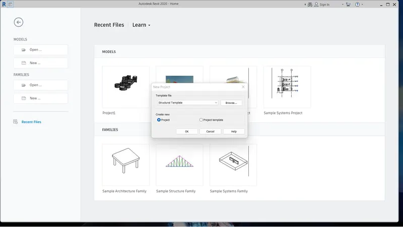
Click on NEW
New Project dialogue box opens
Select one of the Template File: Structural Template
Select one of the options in Create new: PROJECT
Press OK
Create Folder Name REVIT on desktop
After opening of the Template
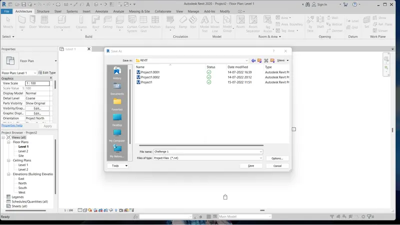
Select FILE TAB
Choose Save
Save in : Desktop > REVIT
File Name: Challenge 1
Press SAVE
RESULT: -
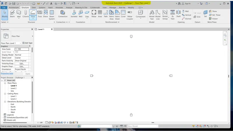
We created a NEW PROJECT File
We saved and then named the Project.
Highlighted the FILE NAME with the marker in the snapshot
2Q]
AIM: -
Save the New Project File
Close and open the File from FILE toolbar
PROCEDURE: -
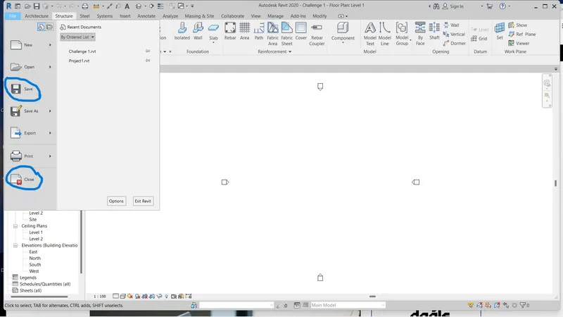
Select the FILE toolbar
Choose SAVE option
Save in: Desktop > REVIT
File Name: Challenge 1
Press SAVE
Select the FILE toolbar
Choose CLOSE option.
We go to the REVIT_HOME
In Recent Files
Under Models Select Challenge 1 file
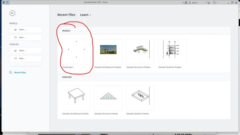
In this way we open the file
RESULT: -
We saved the File.
We closed the file
We opened the File through FILE tab
3Q]
AIM: -
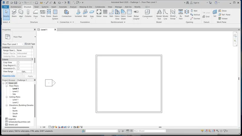
Create a Rectangular layout of wall 40’-0” x 35’-0”
PROCEDURE: -
Select STRUCTURE tab
Choose WALLS
In WALLS select one the options: WALL-Architectural
Go to DRAW pallet

Select LINE
Click on the screen for the Wall start point.
Mention the distance of 40’ units.
Move the cursor perpendicular to the wall till the green dotted line appears.
This ensures wall is perpendicular
Mention the distance of 35’ units.
Move the cursor perpendicular to the wall till the green dotted line appears.
Mention the distance of 40’ units.
Move the cursor perpendicular to the wall till the green dotted line appears.
Mention the distance of 35’ units.
Press ENTER
RESULT: -
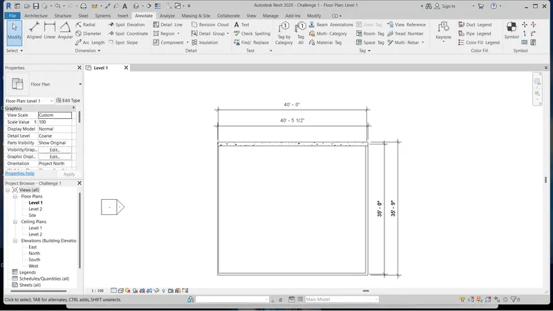
We created a Rectangular layout of wall 40’ x 35’ units.
Familiarized with options to draw a wall.
4Q]
AIM: -
Get familiarize with Annotate toolbar
Use ALIGNED option to add dimension to the layout
PROCEDURE: -
Select the ANNOTATE tool bar
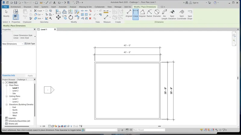
Under DIMENSION pallet select the LINEAR option

Choose the outer corner of the wall and then choose the other corner of the wall.
Press Enter
Under DIMENSION pallet select the ALIGNED option
Choose the outer corner of the wall and then choose the other corner of the wall.
Press Enter
RESULT: -
We marked the Dimension to the Layout using Linear and Aligned options.
Learnt how to mark the dimensions with ANNOTATE tool bar.
5Q]
AIM: -
Switch to different wall types using the Properties Browser.
PROCEDURE: -
Type PP to open the Properties Browser
Right click on the screen
Go to the Browser and select one of the options Project browser.
Select the one of the walls on the screen
On the Left side you can see the properties browser
In Properties browser we see the wall type and thickness.
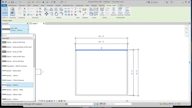
Click on the wall property
From the dropdown list select one of the types.-Interior
Now Select another wall on the screen.
In Properties browser we see the wall type and thickness.
Click on the wall property
From the dropdown list select one of the types: Retaining Wall
RESULT: -
We assigned different wall type properties to each wall of the layout.
Learnt how to change the wall type in Properties browser and assign to the layout.
6Q]
AIM: -
Create a 3D view from the VIEW toolbar.
Save the VIEW with the name.
PROCEDURE: -
Select the VIEW toolbar
Go to CREATE palette
Choose 3D view icon
Select one of the options: Default 3D view.
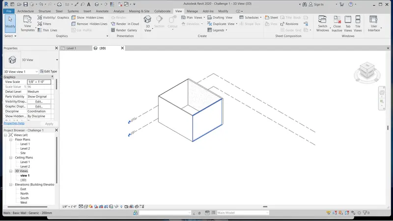
Now the 3D view of the layout displays on the screen.
Go to the VIEW CUBE
Right click on the Corner of the CUBE
From the dropdown list select the SAVE VIEW option.
3D view dialogue box opens
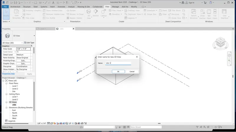
Enter the new name for the view. – VIEW 1
Click OK
RESULT: -
We created the 3D view fom the VIEW toolbar.
We saved the VIEW with the appropriate name.
7Q]
AIM: -
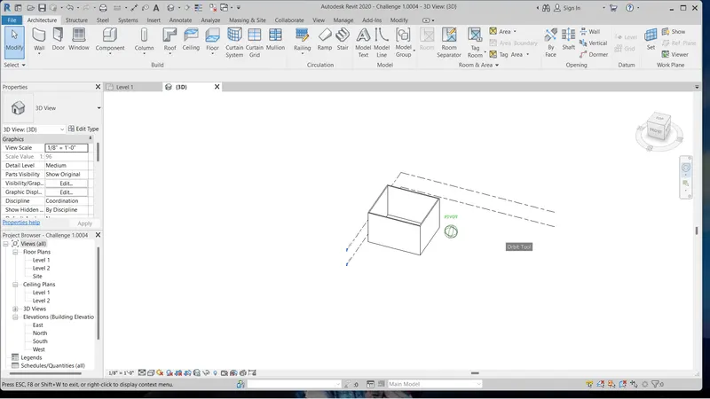
Navigate through the 3D model by using Orbit and Pan in Navigation tool.
PROCEDURE: -
Select VIEW toolbar
Go to User Interface
Click on the Navigation bar
Navigation bar appears on the screen.
Click on the Navigation bar circular Navigation tool appears on the screen
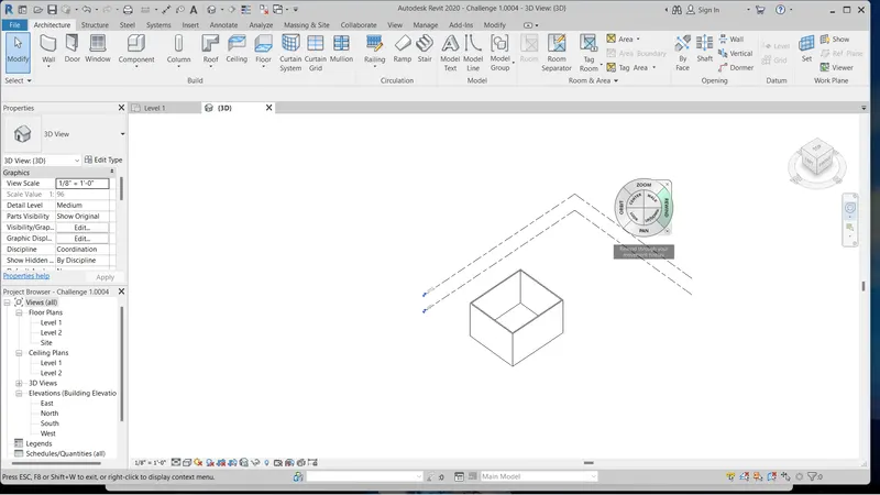
This circle has options:
Pan
Zoom
Orbit
Rewind
Centre
Walk
Look
Up/down
Click on the Orbit option and hold it
You can rotate the layout in 360 degrees.
Click on the Pan option and hold it
We can move the layout all over the screen.
RESULT: -
By using the ORBIT and PAN options we navigated through the 3D model.
8Q]
AIM: -
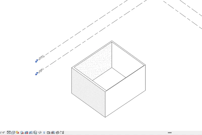
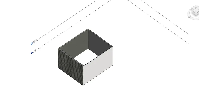
Switch model to Shaded, Realistic, Hidden lines using visibility settings.
PROCEDURE: -
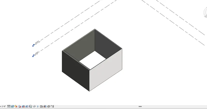
From the BOTTOM toolbar select the visual style.
Select the Visual style and from the dropdown list choose the various options.
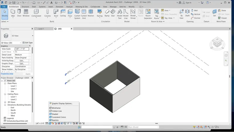
Wireframe
Hidden
Shaded
Realistic
Consistent Colours.
RESULT: -
We learnt how to switch the model from various visual styles in visibility settings.
9Q]
AIM: -
Turn the Sun Path on and off to view shadings in the Layout.
PROCEDURE: -
In the BOTTOM tool bar there is a dedicated option for SUN PATH
Set 3D view on the Screen.
Select the Sun path option
Here we can see
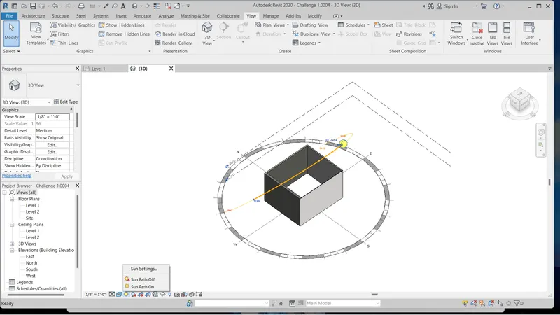
SUN PATH ON,
SUN PATH OFF
SUN SETTINGS.
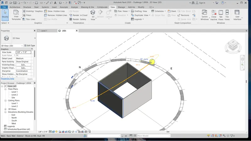
Turn on and off the sun path
If we need to do any changes then go to SUN SETTINGS.
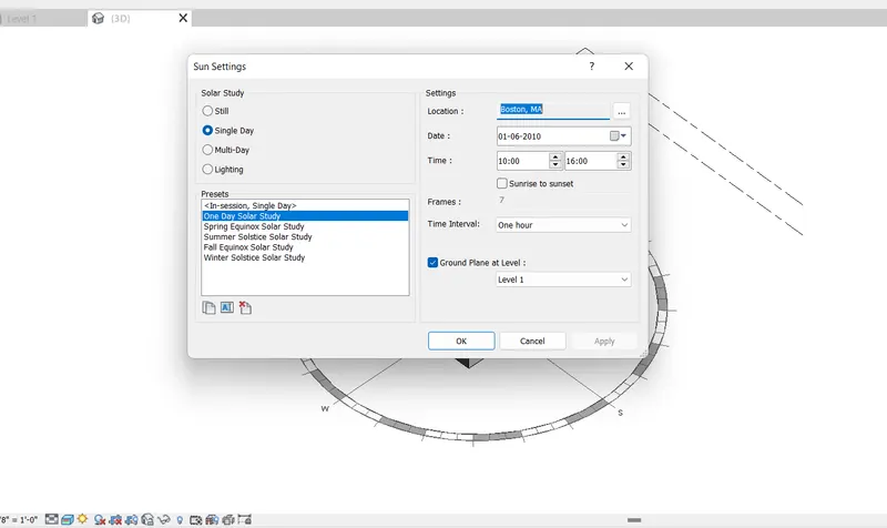
Sun settings dialogue box opens
Select solar study,
Change location and time.
Press OK.
Turn on the SUN PATH
RESULT: -
10Q]
AIM: -
Familiarize with the MANAGE tool bar to enter Project Settings, project name, and project issue date.
PROCEDURE: -
Select the MANAGE tool bar
Go to Settings pallette
Select the Project Information icon

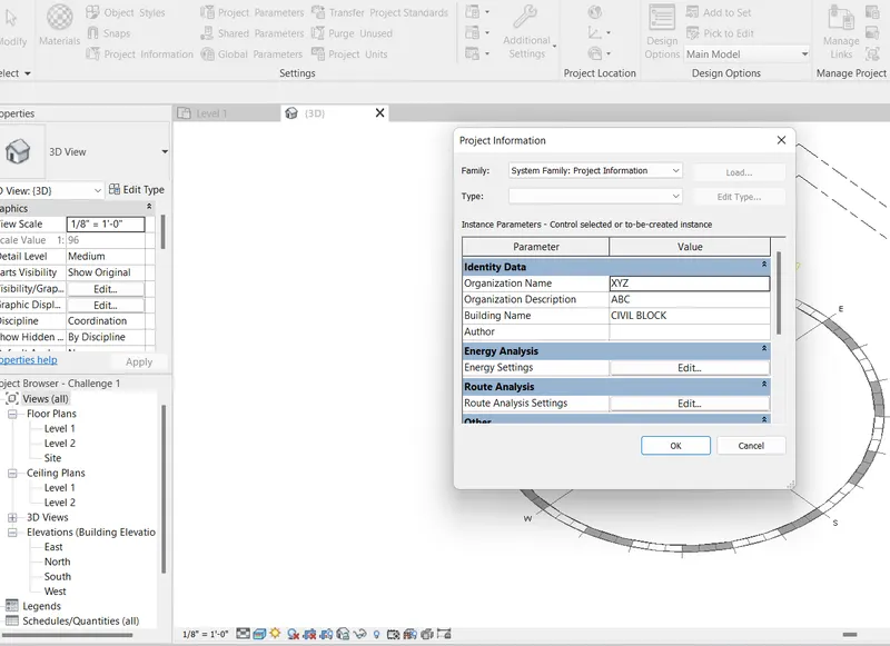
Project Information dialogue box opens.
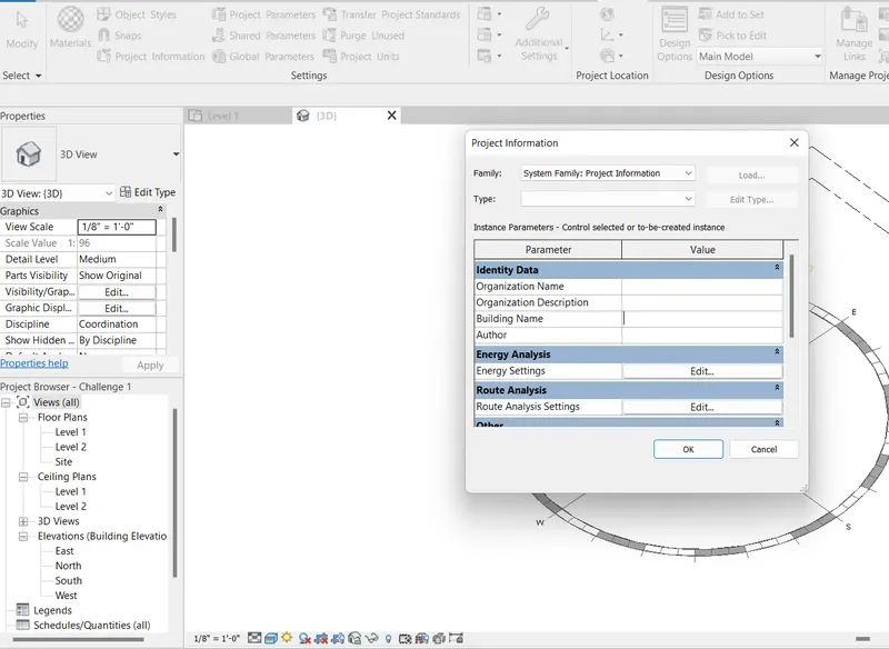
Enter the required data.
Press OK
RESULT: -
11Q]
ANALYSE toolbar is used to perform structural analysis of the building.
It has various analytical tools to enable the structural process
- Boundary conditions-Defines point, line and Area boundary conditions in an analytical model to communicate engineering assumptions about support conditions.
- Loads- Applies point, Line and Area loads to a model to assess possible deformations and stresses in the model.
- Load Cases- Adds and edits load cases for the analytical model.
- Load Combinations- Adds and edits load combinations for the analytical model.
12Q]
Links that Revit supports to be linked to the model are:
LINK REVIT- links another revit model to the current model.
LINK IFC- links an IFC file to the current project to reference its information for additional design work.
LINK CAD- links a CAD file to the current Revit project.
LINK TOPOGRAPHY- links existing topography to the current Revit model.
DWF MARKUP- links marked-up DWF files into a Revit project so you can see the
mark-ups on corresponding sheets.
POINT CLOUD- links a point cloud file in to the current project.
CO-ORDINATION MODEL- links a NWC or NWD to provide context for the Revit model.
13Q]
Collaboration tab enables Working Together so team members can work on a model simultaneously.
Collaboration tab enables Work-sharing so multiple users can work on different parts of one project.
Work-sharing allows simultaneous access to a shared model through use of a central model.
Central model acts as distribution point for all the changes made in the model.
By using work sharing multiple team members can work on a single model
Collaboration enables Cloud Sharing
Cloud Sharing allows to collaborate on models in the cloud so that we can centralize all project design data, and improve communication and
collaboration across the entire team.