Introduction to REVIT concepts
- AIM: To create the project and name project appropriaeky
- PROCEDURE:
- Initially open the revit software
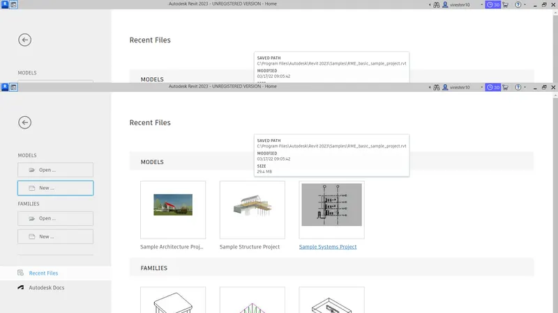
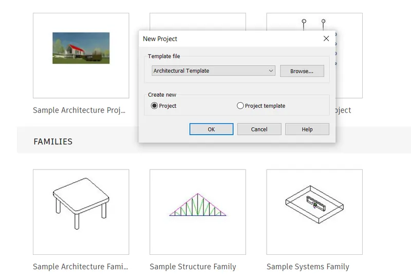
- choose architectural template then click on project and then click on ok
- Now,open revit software opens
- Click on the save icon which is on the left side of screen then a window opens
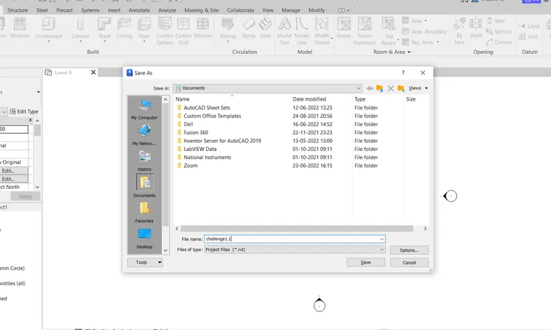
- Hence file name is saved as challenge1.1
- Now close and open the file using file toolbar
- So, now close the revit software
- Again ,open the revit software
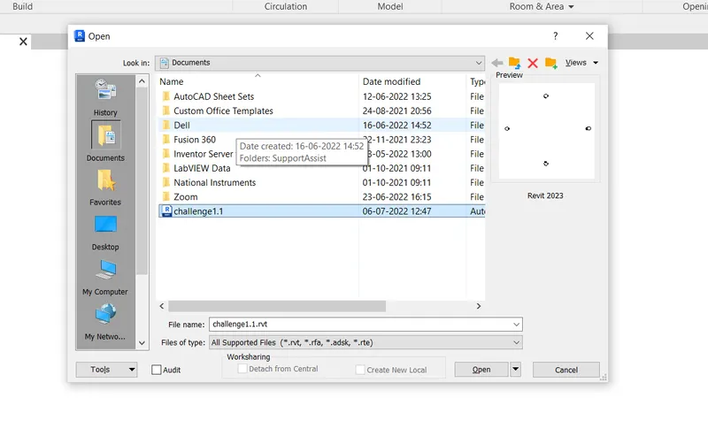
- Then go to the file menu and click on open
- From open menu open the file named challenge1.1
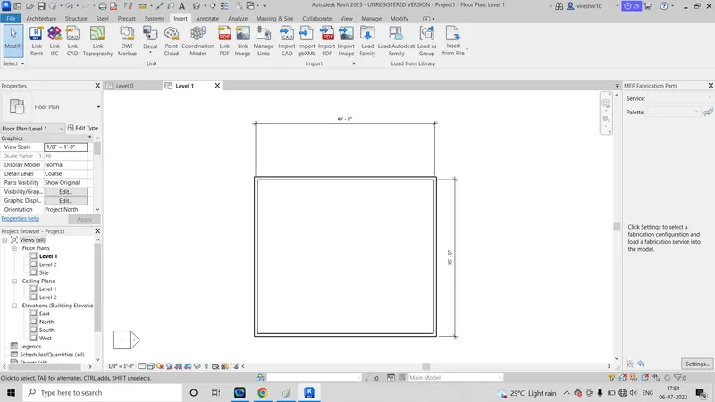
- AIM: To create the rectangular layout of a wall about 40' x 35'
- PROCEDURE:
- Initially open the revit file
- Choose the imperial template
- Then go to the architectural panel and choose the wall and create the wall o f 40' x 35'
- RESULT
- AIM: uSING THE ANNOTATE BAR USE DIMENSION TO GIVE THE DIMNSION TO THE RECTANGULAR LAYOUT
- PROCEDURE:
- Initially open the revit software
- Create the wall in the imperial template
- Now go to the annotate select the linear dimension and give the dimensio to the recrangular layout
- RESULT
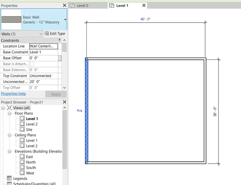
- AIM: Use the properties browser to switch between two diffrent wall types
- PROCEDURE
- Initially open the revit software
- Createthe wall in imperial template
- Now select the wall then go to the properties panel
- In the properties browser go to the wall types and select the generic- 12' masonary wall
- RESULT
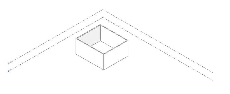
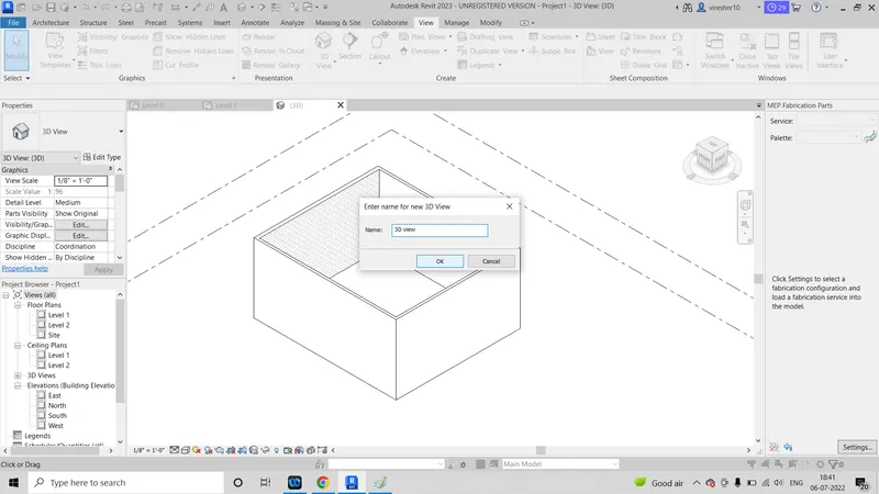
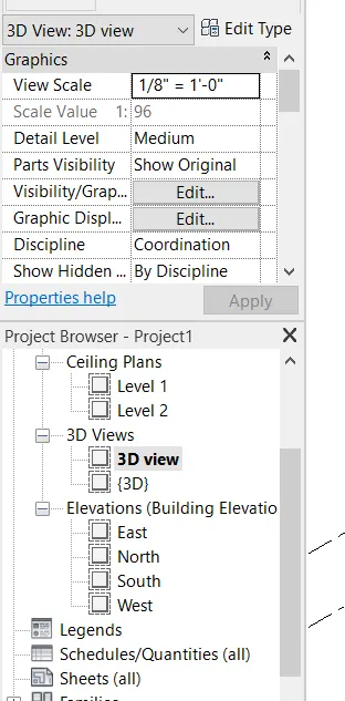
- AIM: To create 3D view from the toolbar and give the appropriate name
- PROCDURE
- Create the reactangular layout as shown in the previous pictures
- Now go to the view tab click on the 3d view
- Now go to the navigation bar and click on the steering whell and give the appropriate name to the 4d view
- RESULT
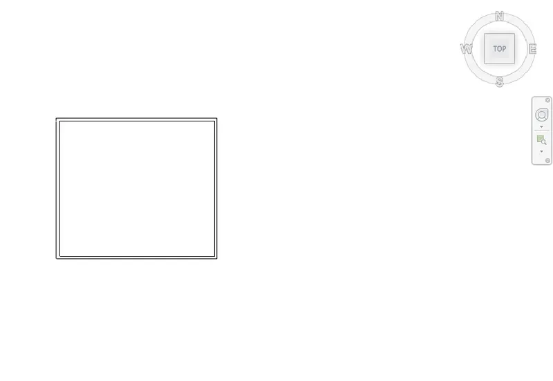
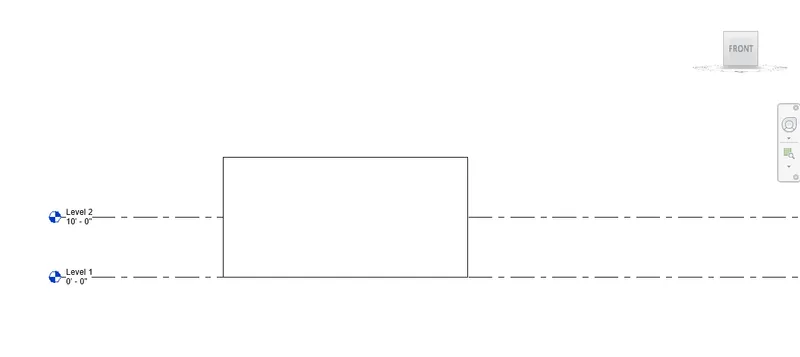
- AIM: To navigate through 3d view using view cube through model layout crated
- PROCDURE:
- Click on the view cube and change the orientation to diffrent views
- RESULT
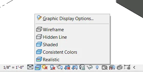
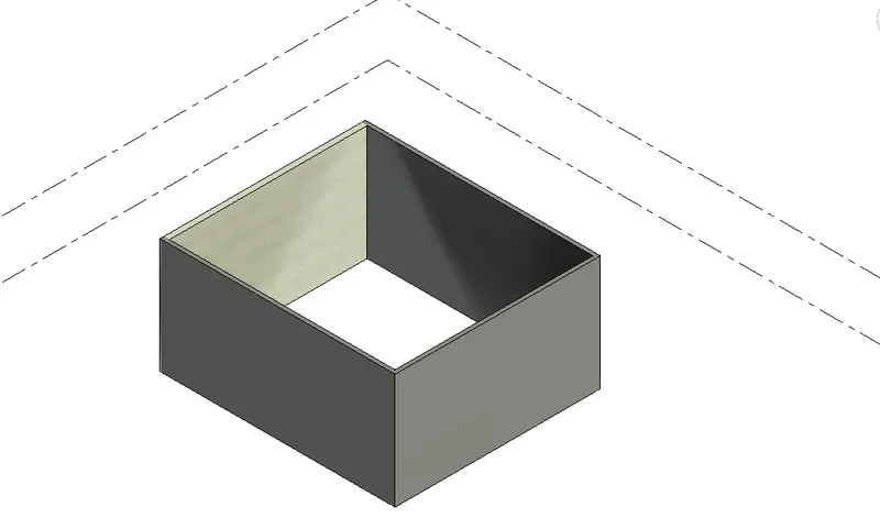
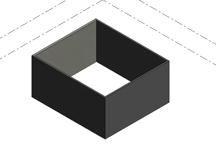
- AIM: To switch the model to shaded , realistiic ,hidden line option by using visibiliy setting option
- PROCEDURE:
- Now go to the visibility section which can be accessed from below level
- Now select the model as per request
- RESULT
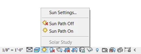
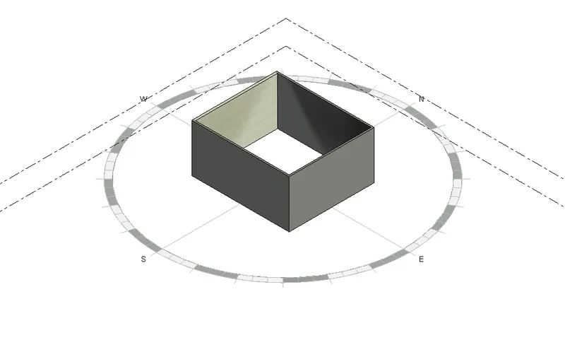
- AIM: To turn the layout sunpath on and off to view shading in the daylight
- PROCEDURE
- Create the realistc view of the drawing
- Now make the sunpath on from below level toolbar
- RESULT
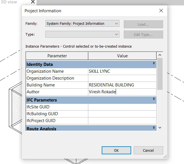
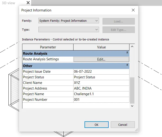
- AIM: To use the manage toolbar to enter project setting ,project name and issue date
- PROCEDURE:
- Go to the manage toolbar
- click on the project information and fill in the information
- RESULT
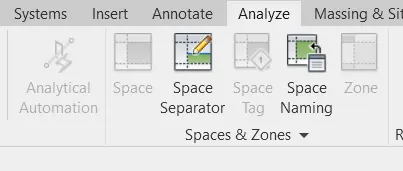
11. Analyze the toolbar in Revit
- Analyze toolbar can be used to do structural analyze
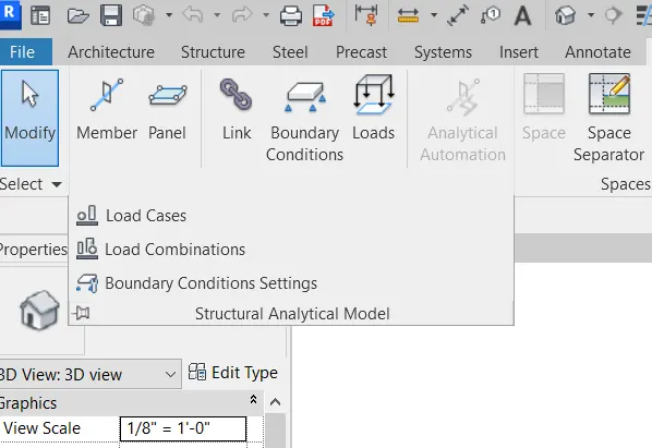
- Verious analtical model tools are
- Boundry conditions are option enable to define points ,line,area boundry conditions in an analytical model.verifies that the boundry conditions in an analytical model. varifies the boundry conditions familly type are loaded and assigned in the structural setting menu
- Load option appilies point ,line area loads to a model each load model is a familiy containing instances and parameter types.Applies load by sketching
- Load cases: adds and edits load cases for analyical models
- Load combination:adds ans edits the load combination for analytical models.Setting load combination includes defining its name ,formula type and stage
-Other analytical tools are
- Adjust:Adjust the analytical models of the structural member in relation to those elements to which it joins sosme adjstments of the analytical models locations may be enquired before structural models are transferred to analysis
- Reset:Reset the analytical models alignment to auto dictate .Auto dictate removes both projection and manual projection and manual adjustments from analytical models
- Support: Verifies structural element such as beam,column,slab, wall are joined to support elements.It contains criteria for checking the member
- Consisstency:Verifies the analytical model and physical model for consistency.Examine the warning and make changes to the model as needed to rectify
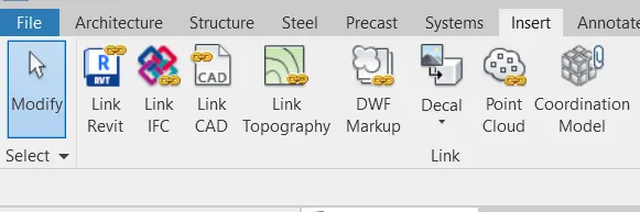
- LINK THAT REVIT SUPPORT TO BE LINKED TO THE MODEL
- LINK IFC:Link an ifc file to the current projects to reference its information for additional design works
- LINK CAD:Link an cad file to the revit projects linking is similar to xref in autocad
- LINK TOPOGRAPHY:Links an existing topography to the current revit model
- DWF MARKUP:Link markup file to the revit projects so that mark up can be seen in the drawing
- DECAL:Places an image on the surface of a building model for an rendering .Decals can be placed in the flat
- POINT CLOUD:Links a point cloud file into project
- COORDINATION MODEL:Links an NWD file to provide context for an revit model
- COLLABARATIVE TAB IN REVIT
- Collabarative tab enables work sharing in the revit
- Multiple revit model can be linked together allowing to work in the context
- Collabaration is needed when people working on the projects are not an same geographic location
- Collabaration involes creating an master project model known as central model from an existing model
- Central model acts as distribution point for all changes to be made
- All users should have copy central model ,edit locally in the workspace