Introduction to REVIT concepts
TASK : 1
Aim:
To Create a New Project using the Software Revit 2023.
Procedure:
- As a Beginning Open the Revit 2023 from the system.
- After openning the Revit in the left we have to click the New Projects in the Model Category. Since we will be having 2 options Which is Model and another one is Families. We have to choose (Model - New Projects).
- After opening the New Projects we can see the dialog box as Template File. Were We have to choose any one template in which we are going to start our project.
- In the template file we will be selecting any one of the Construction / Architectural / Stuctural template.
- Below the Template File we can notice the two option Project and Project Template. We should check the Project and then we have to proceed by clicking the button OK.
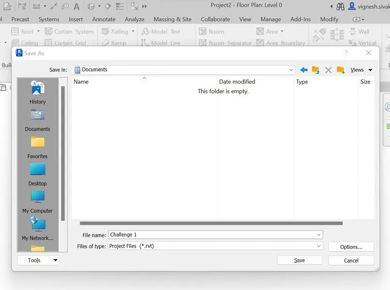
- After opening the Project, Click the Icon File in the top left corner - next click on the Save to save the Project File in the required file location.
- Before clicking Ok Button the Save Dialog box, We have to Gvie a Specific Project Name for our easy Identification. For Example: Here I gave the name as Challenge 1.
- We can save the Project as Challange 1 and Select the Option as OK.
- Now we have saved the Project as Challenge 1.rvt.
- Finally we can see the Screenshots of the task below.

TASK : 2
Aim:
To Close and Open the Project using the Icons of File toolbar.
Procedure:
- Click the Icon named File on the top left corner of the revit file.
- In the File Icon We will have save option, Click on the save option save the Project.
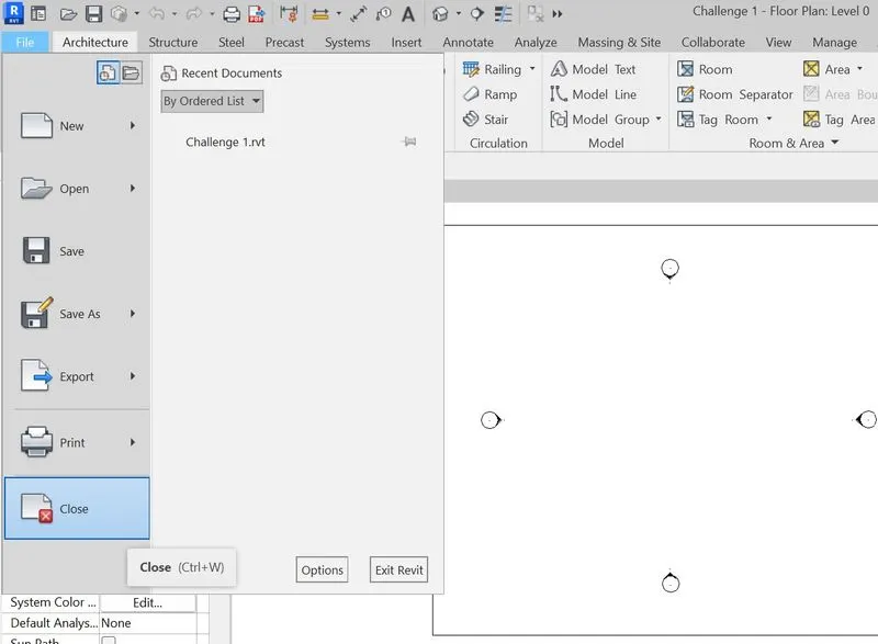
- After saving the file, Once again click the Same icon File and the We can select the close Button to cloce the Project (Challenge 1).
- After closing the Project "Challenge 1", We will open the Project.
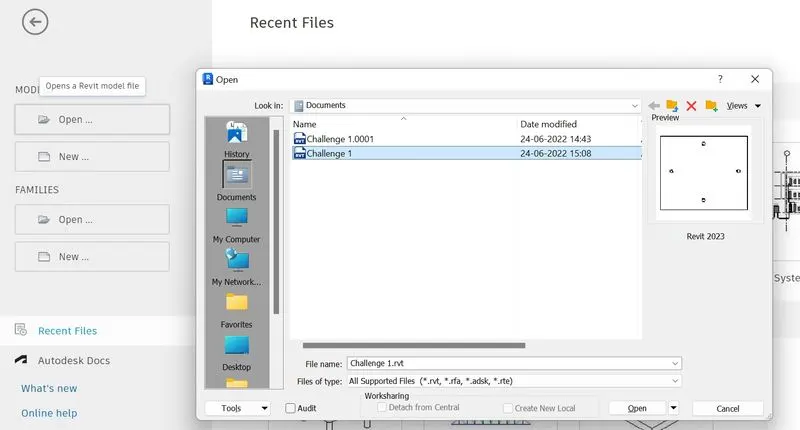
- Now we are in the Beginning of our Revit 2023 File. Here we have to select the Icon Open in the Model category.
- Now the open icon will show the Recent Projects which we were working. There we can select the Project Challenge 1 or else We can browse the file to open the Project were save Previously.
- After Clicking the Project - Challenge 1.rvt., - Revit will Open the Project.
- Finally we can see the Screenshots of the task below.
TASK : 3
AIM:
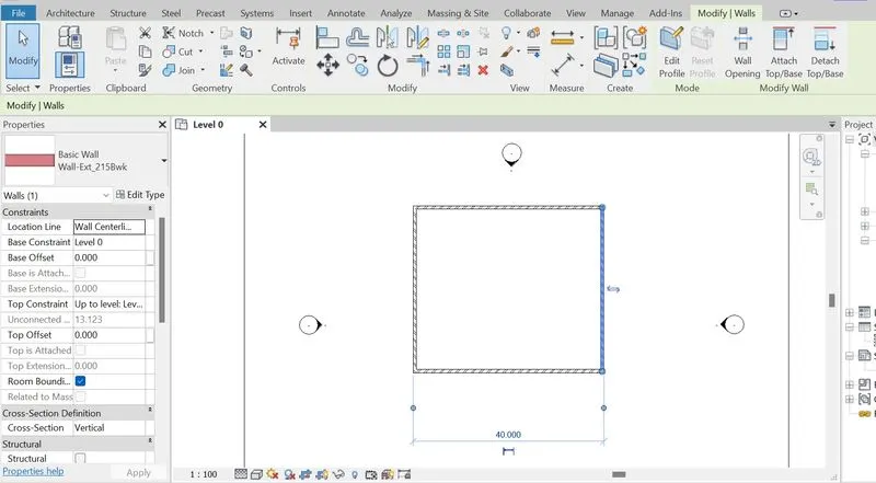
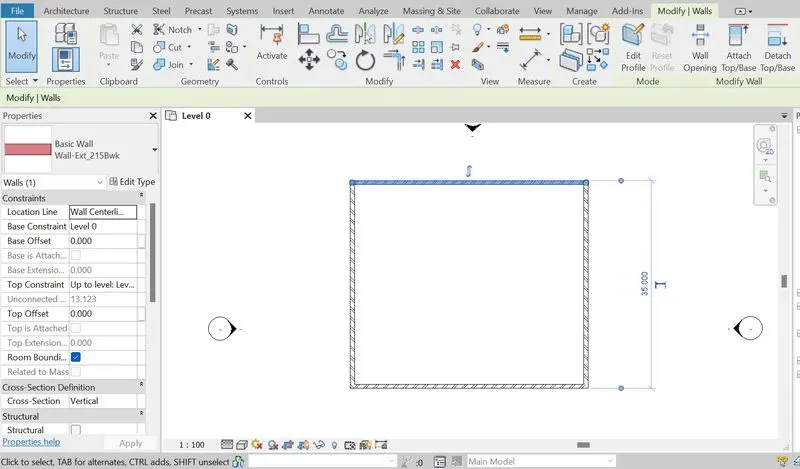
To draw a wall of size 40' X 35'.
PROCEDURE:
- On the Architectural Tab in the top left click on Wall icon.
- After clicking on the wall icon we can see the modify tab to draw the wall on the work space.
- We will have the options of drawing wall in different shapes like Line, Rectangle, circle, pentagon, etc.,
- By selecting the Line Option we can draw the wall for 40' first followed by 35', and repeat the same to form the Rectangular Layout of Walls.
- Finally we can see the Screenshots of the task below.
TASK : 4
AIM:
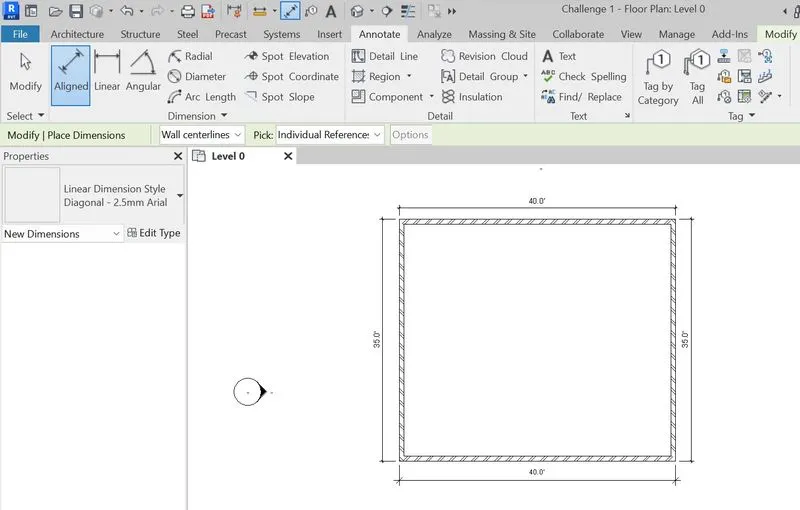
To use the Annotate tool bar to allign the layout and add the Dimensions to the layout.
PROCEDURE:
- Click the Annotate tool bar in the top.
- see the different types of annotations under the Dimensions.
- Select the Either Linear or Aligned Dimension to add dimensions to the layout.
- After selecting the Aligned Dimensions select any one edge of the wall as starting point and select the othe edge of the wall in opposite side.
- By repeating the same procedure on the other side we will get the dimensions covering the layouts.
- Finally we can see the Screenshot of the task below.
TASK : 5
AIM:
To change the different types of walls by using Properties Browser.
PROCEDURE:
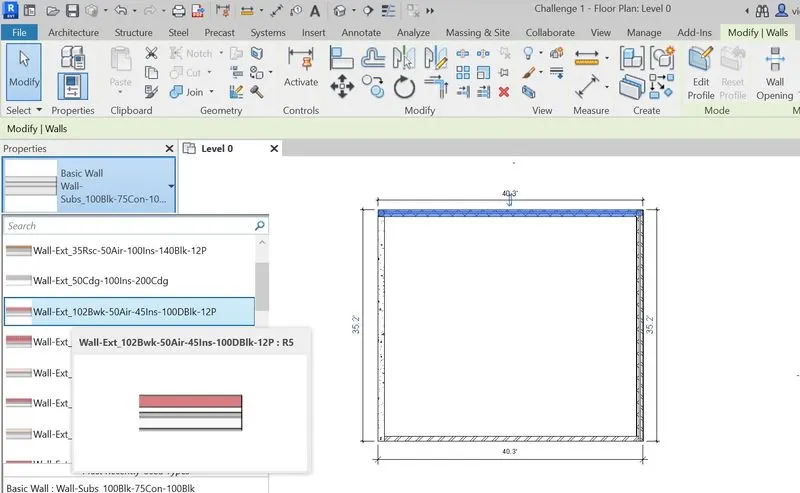
- Select the wall which we have already drawn in the workspace.
- In the Properties Browser a drop arrow will be in the top, by clicking the drop arrow different types of wall and with different wall thickness will be available.
- We can select the required walls of each side of the rectangular Layout.
- After clicking the selected wall type we can notice the change in the work space also.
- Finally we can see the Screenshot of the task below.
Task : 6
AIM:
To create a 3 Dimensional View of the project.
PROCEDURE:
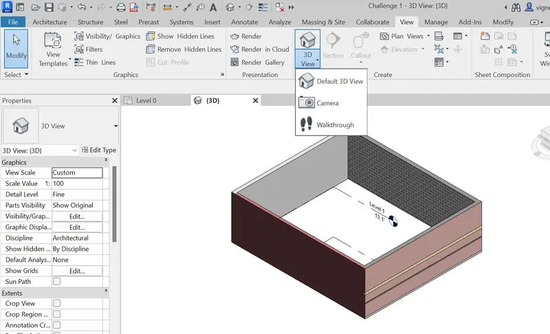
- Select the VIEW Icon on the toolbar.
- In the VIEW Icon under the create option we can find the Icon 3D View, Click the Icon 3D View Arrow.
- After Clicking the 3D View Icon we can see the option called Default 3D View, Click the Default 3D View.
- After Clicking the Icon additional tab will be opened in the workspace naming 3D view.
- Now we can View the 2D Layout directly in the 3 D View.
- By right clicking the Top Corner of the View Cube a dialogue box appears.
- In the Dialogue box we can find the option called save the view.
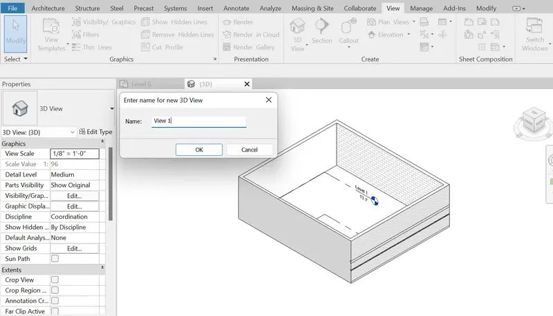
- By clicking the option Save the view We cansave the View in the appropriate name (View 1).
- Finally we can see the Screenshots of the task below.
Task : 7
AIM :
To Navigate the Created 3 D model by using the View Cube and Navigation Bar.
PROCEDURE:
- Now we can view the 3 D model, In the right side of the WorkSpace we can find the Navigation Bar.
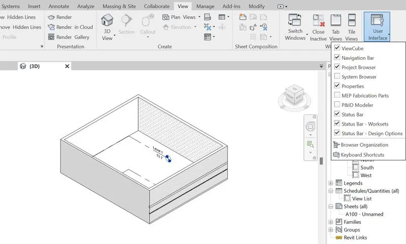
- Incase if there is no Navigation Bar in the right side of the workspace, We can Find the navigation bar by clicking in the view toolbar.
- In the View Toolbar we can find the Icon called User Interface.
- By clicking the User Interface Icon we can find the Navigation bar as unchecked, By Checking the Navigation bar on we can find the Navigation bar on the Right side of the Workspace.
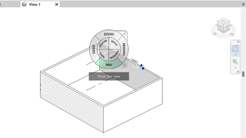
- In the Navigation Bar select the Navigation Wheel to use the Orbit, Pan, Zoom, etc.,
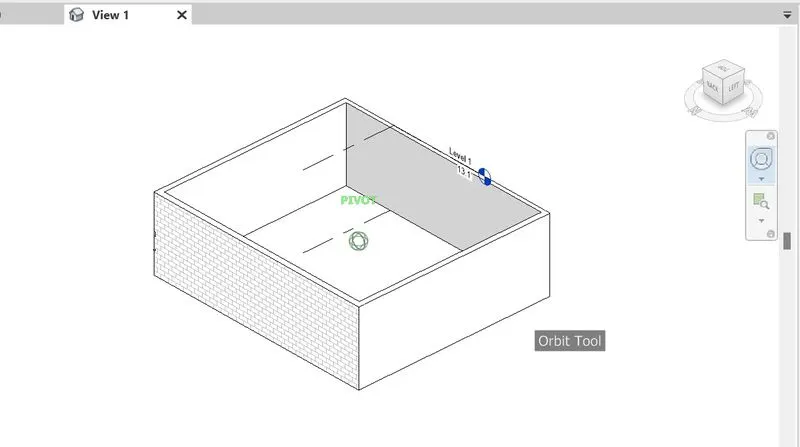
- The use of Orbit tool is to rotate the Model 360 degree.
- The use of Pan tool is to move the model.
- For using the Orbit tool we have to click the Orbit icon in the navigation wheel to rotate the Model.
- Mean while we have to click pan icon in the navigation wheel to move the Model.
- Finally we can see the Screenshots of the task below.
TASK : 8
AIM:
To switch the model to Hidden line/ Shaded/ Realistic Model.
PROCEDURE:
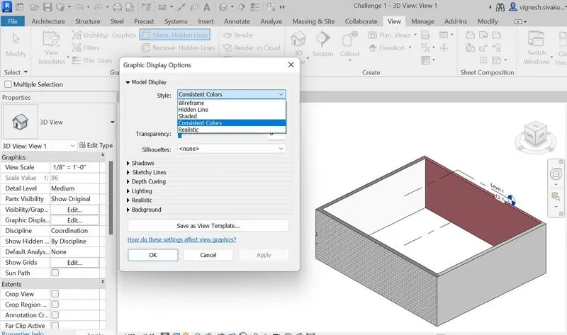
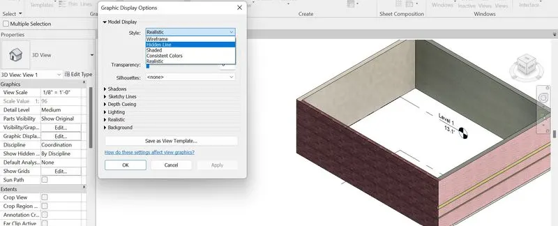
- In the Properties browser we have a property called Graphic Display.
- In the Graphic Display click the edit option, after that a dialogue box appears naming Graphic Display Options.
- In the Graphic Display option click on the Model Display option which is the First one of that option.
- After clicking the Model Display we have style option in that style option we can change our graphic display to respective styles like Wireframes/Hidden lines/Shaded or Realistic views and click Apply and then Click OK.
- Finally we can see the Screenshots of the task below.
TASK : 9
AIM:
To switch on the Sun Path ON and Off to view the shaddings of the Model.
PROCEDURE:
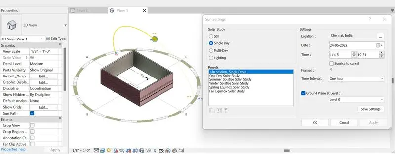
- In the Properties browser under Graphics Option we can Find Sun.
- By checking the option Sun ON, we can get the SUN PATH landing on the Model.
- Right click on the sunpath, we can find the option called Sun Settings...
- By clicking the Sun Settings... We can locate the Model Location.
- We can use Solar Study for finding the shadows of the model according to regular period of time.
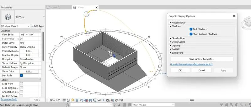
- And for the switching on the shadows again in the Properties Browser, Under Graphics option, click the edit option in the Graphics Display.
- In the Graphic Display Option click on the shadows option.
- In the Shadows option checkin both the Cast Shadows and Show Ambient Shadows.
- After Checking both the icons we can give Apply and then OK.
- After that we can see the shadow visible in the Model.
- Finally we can see the Screenshots of the task below.
TASK : 10
AIM:
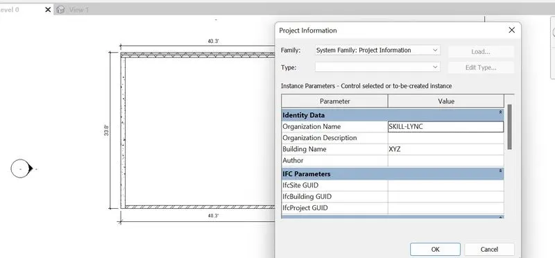
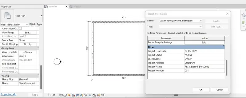
To enter the Project Details.
PROCEDURE:
- Click on the Manage Icon on the Tool Bar.
- In the Manage tool bar we have the option called setting. In the Settings option we have Project Information.
- By clicking the Project Option we will have a Dialogue Box appearing on the screen called Project Information.
- In the Project Information we are going to will the values according to the parameters.
- Organization Name as SKILL-LYNC, Building Name : XYZ.
- Project Status as Active, Project Issue Date, Project Name, Project Number.
- After Entering all the Details click OK button.
- And finally the Project Details has been entered into the Projects.
- Finally we can see the Screenshots of the task below.
Question 11:
Analyse toolbar helps you to perform analysis on our structural part of the building and it helps to perform the Energy Analysis also. The boundary conditions enable you to define point line and area boundary conditions in an analytical model.
Question 12:
The links thats Revit Supports are CAD links, Revit links, IFC links and Topography links.
Question 13:
Collaboration tab in Revit helps to link multiple Revit Files such as Architecture, Stucture, MEPF files and enables to work simuntaneously from different geographical location with the help of BIM 360 and to work locally with the help of Local Area Network connections by using the Central Model which saves the Project to the server locally or through Cloud sharing which can be used to work across the world. Collaboration Tool helps the Team Members to work simuntaneously all together at the same time with the help of worksharing without any disturbance in the Project.
Finally the Challenge 1 has been completed.