3D Creation of Celing, Roof, Architectural plan, Structural plan, Sectional view, Elevation view and Camera specific view for a house plan using REVIT
TASK : 1
AIM:
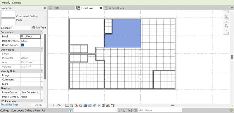
To model a Ceiling from the architecture tab above the walls at the first-floor level.
PROCEDURE:
- Open the First Floor Reflected Celing Plan (RCP) from the Project Browser
- In the Ribbon tool bar click the Architecture Tab Click the Celing under the build option.
- After clicking the Celing In the Properties browse, Select the celing type, to be Plain or Grid Celing
- We will have two option in modelling Celing Automatic celing and Sketch celing.
- Automatic Celing will create the celing by clicking the rooms of closed boundaries.
- While in Sketch Celing we will Draw the celing boundary over the Rooms in the closed loops to create the celing.
- After Drawing the Celing boundaries check for the Closed loops and no intersection of lines and then Click the finish edit mode option.
- Thus the Modelling of celing is completed.
TASK : 2
AIM:
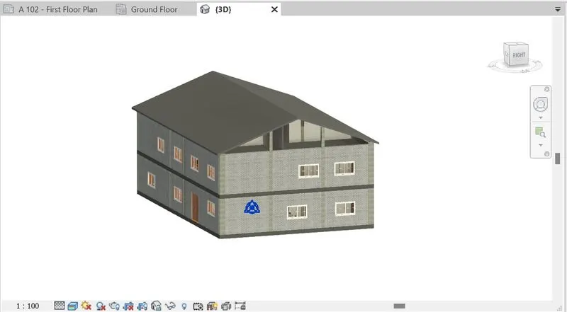
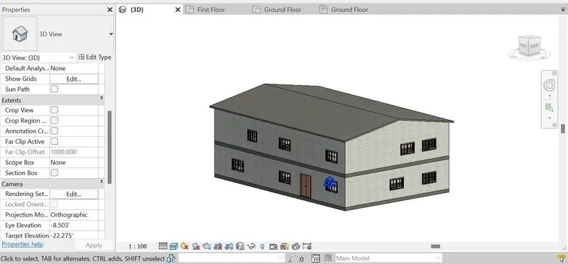
To model a roof above the ceiling by selecting the footprints of the ceiling. And adjust the roof slope to 10 degrees.
PROCEDURE:
- Open the First Floor Plan from the Project Browser.
- In the Ribbon tool bar click the Architecture Tab Click Roof under the build option.
- We will have 4 options in modelling of Roof. We will choose the First option which is roof by footprint.
- After Selecting the option Roof by footprint, we will get a dialogue box for selecting the Lowest Level Notice.
- After selecting the Lowest level In the Properties browse, Select the Roof Thickness and the Materials.
- Use the draw tool option to draw the roof boundary over the plan, without intersecting and must be of closed loops to create the Roof.
- After Creating the roof boundary click the finish edit mode option.
- Thus the Modelling of Roof is done.
- Now we will adjust the slope to 10 degrees. For that we need to Check the Units for the slope whether the slope unit is in degree or ratio.
- If it is in Ratio using the Project units change it to Degees.
- After Changing the units to degrees, Select the Roof in the 3D view.
- In the Properties browser Select the Slopes and change the slope to 10 degrees.
- Now Attach the Walls to the roof by Selecting the Attach to Top / Base option and Select the Roof which we created.
TASK : 3
AIM:
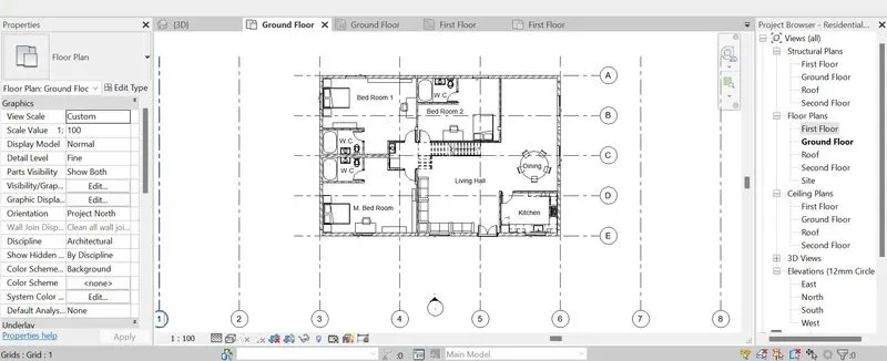
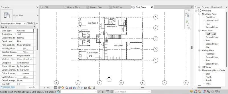
To create plan views for ground floor level and first-floor level including all the walls, floors, and components. Separate them to Architecture and Structural plans.
PROCEDURE:
- Open the First Floor Plan from the Project Browser.
- In the Ribbon tool bar click the View Tab.
- Click the Plan Views under the Create option. There we will have the seperate Views for the discipline.
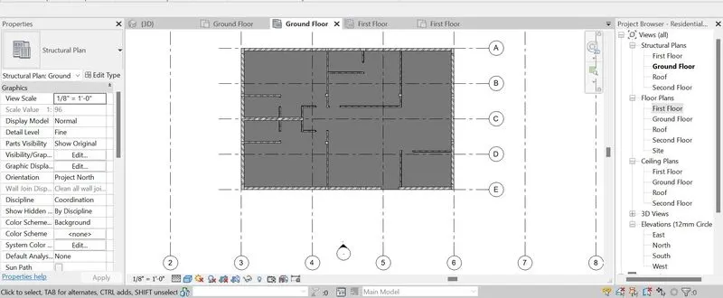
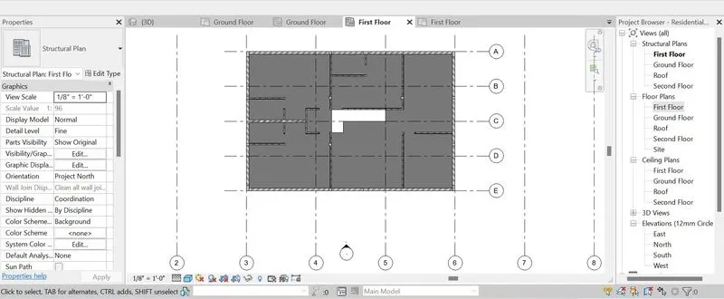
- Select the Structural plan, Select the Floors and then Click OK.
- Thus the Structural floor Plan are Created.
- In the structural plans, we must have details of only walls, floors, and columns. now we chan change the Discipline from Coordination to Structural in the Properties Browser.
STEP 2: Architecture Plan
TASK : 4
AIM:
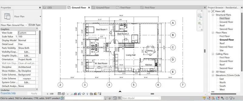
To add dimensions to all the walls and floors with reference to the longitudinal and transverse grids created in the project file.
PROCEDURE:
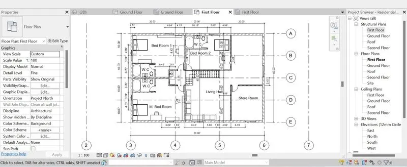
STEP : 1 Architecture Dimensions
- In the ribbon tool bar use the Annotate tab to add the dimensions.
- In the Annotation tool bar select the Linear or Aligned Dimension to add the dimension to all the walls with respective Grids.
- After adding the dimensions add the dimensions for the components placed with in the building.
- Do the same for the first andthe ground floors.
- Add the overall dimensions for the grids.
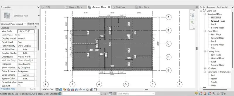
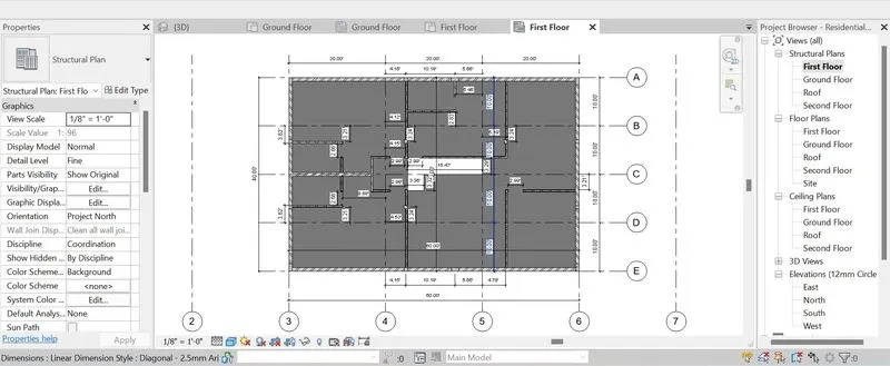
STEP : 1 Structure Dimensions
- In the ribbon tool bar use the Annotate tab to add the dimensions.
- In the Annotation tool bar select the Linear or Aligned Dimension to add the dimension to all the walls with respective Grids.
- After adding the dimensions add the dimensions for the framing elements Such as Columns & beams placed in the building.
- Do the same for the first andthe ground floors.
- Add the overall dimensions for the grids.
TASK : 5
AIM:
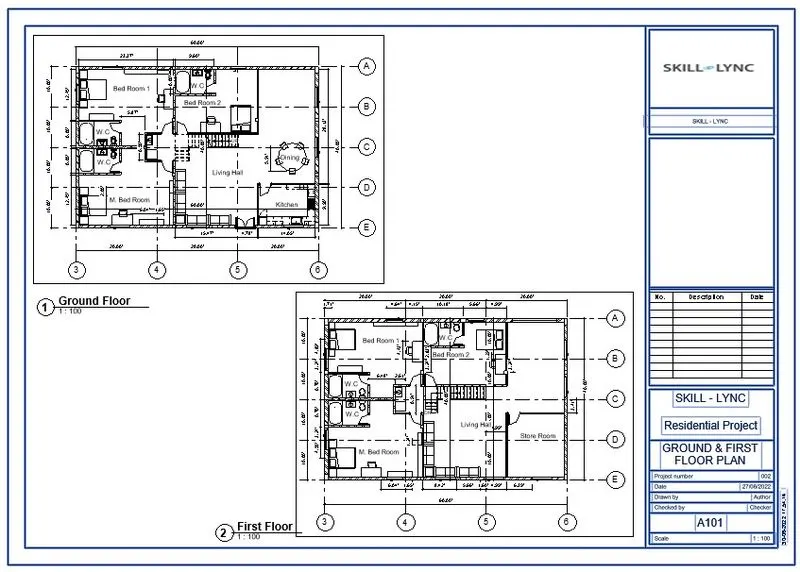
To create a sheet template from the view tab and adjust the parameters on the sheet to add appropriate views.
PROCEDURE:
- In the Ribbon tool bar click the View Tab.
- Click the create Sheets under the Sheet composition option.
- We will get a new Sheet dialogue box
- We should load the Required Sheet like A0, A1, A2, A3 & A4.
- For Loading the sheet, Click Load option in the top right of the new Sheet dialogue box.
- We will be in Libraries tab, There Search for the Titleblock, were we can get the required sheet.
- Load the Sheet into the project.
- After Loading the Sheet, Click the Sheet and Click the Edit Family option under the modify tab in the Ribbon tool bar.
- In the Edit family option we can change the parameters of the sheet and then load to project.
- Drag and Place the floor plan in the Sheet and Edit the Parameters According to the sheet in the properties browser.
TASK : 6
AIM:
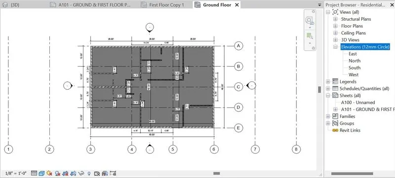
To create the elevation views, looking at your building from East, North, South, and West.
PROCEDURE:
- In the Ribbon tool bar click the View Tab.
- Click the elevation under the create option.
- Place the elevetions the on all the four Directions of the building with respect to the North, South, East and West.
- In the Project browser, under the Elevations Rename the views to North, South, East and West.
TASK : 7
AIM:
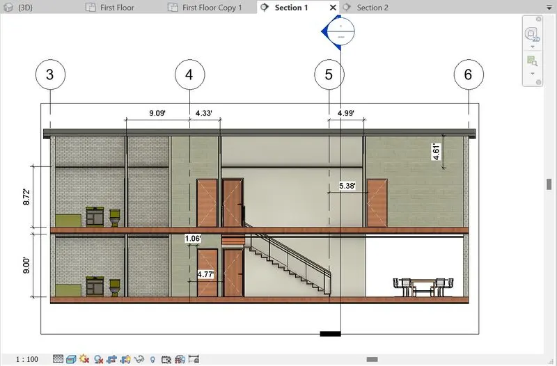
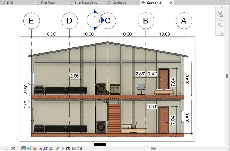
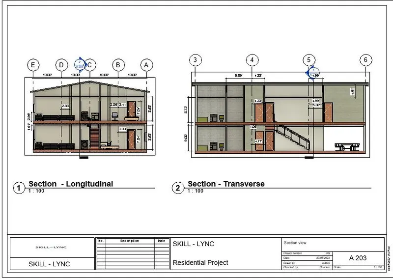
To produce section cut through each room either cutting across longitudinally or in a transverse direction.
PROCEDURE:
- In the Ribbon tool bar click the View Tab.
- Click the section tool under the create option.
- In the Floor plan draw the section longitudinally.
- Same as the above draw the section in transverse direction of the room.
- Rename the section view in the Project Browser.
- Open the section view from the Project Browser one by one to view them.
TASK : 8
AIM:
To classify the views, Plan Views, Section Views, and Elevation views to either Design or Documentation category using Properties browser
- PROCEDURE:
In the Properties Browser we can change the Scale, Display mode, Detail Level, the option in the Graphic, Underlay, extents & Identity Data.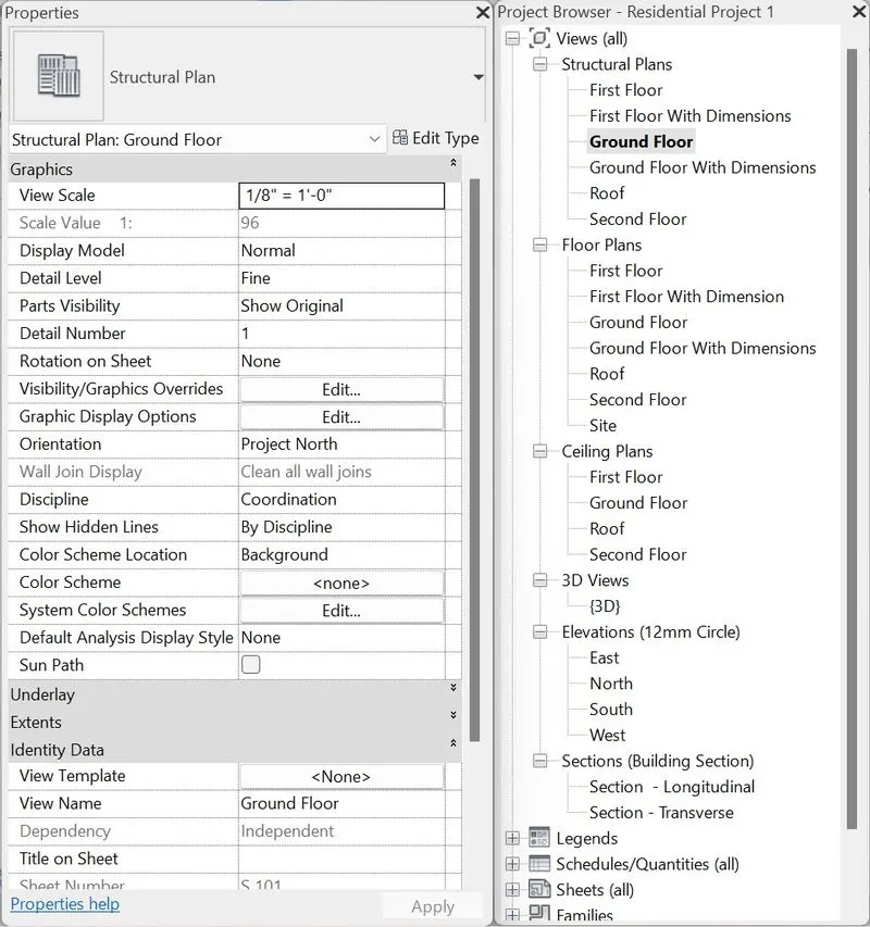
TASK : 9
AIM:
To create create multiple sheets as follows
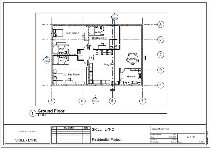
a. A 101- Ground Floor Architecture Plan
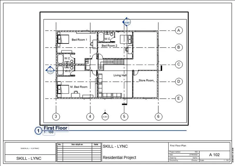
b. A 102- First Floor Architecture Plan
c. A 103- Roof Plan
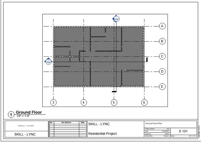
d. S 101- Ground Floor Structural Plan
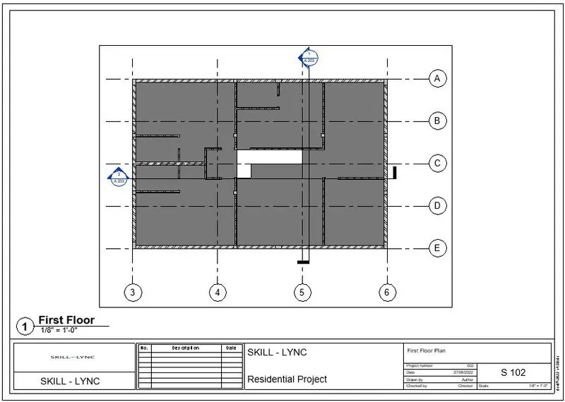
e. S 102- First Floor Structural Plan
f. S 103- Roof Framing Plan
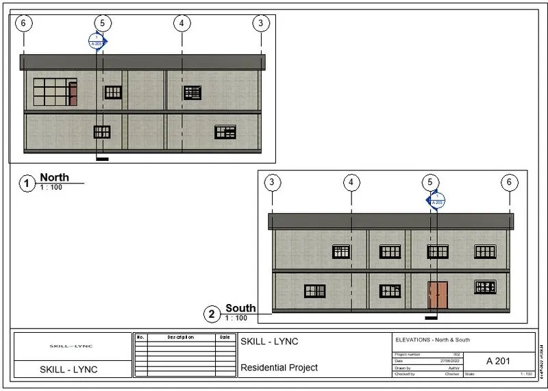
g. A-201- North-South Elevations
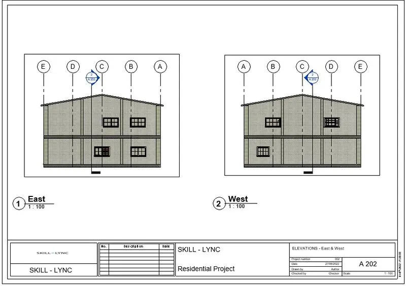
h. A-202- East-West Elevations
PROCEDURE:
- In the Project Browser, Click the Sheets option.
- Open the sheet, Drag the Views to the sheet according to the Project.
- Enter the Sheet Parameters in the Properties browser.
- Arrange the Sheets with the appropriate Discipline.
- We can see the Sheets bellow.
TASK : 10
AIM:
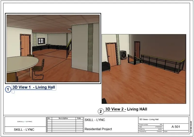
To create a camera-specific view or a 3D view in each room ( living, dining, bedroom). Based on the views create a new set of sheets starting A-501.
PROCEDURE:
- In the Ribbon tool bar click the View Tab.
- Click the 3D View options we will have the option called Camera.
- place the camera in any of the room.
- After Placing the camera we can focus the camera covering the enitre room.
- Do the same for the other rooms also.
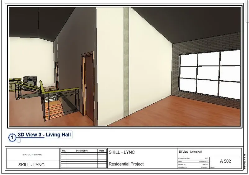
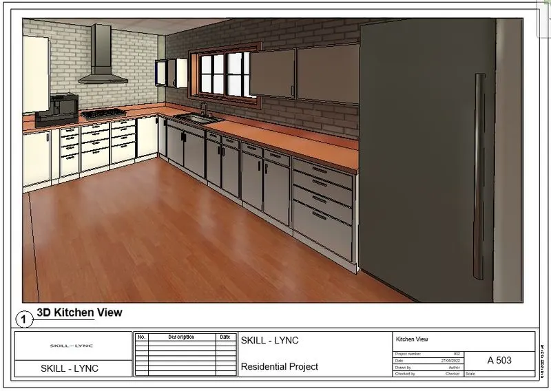
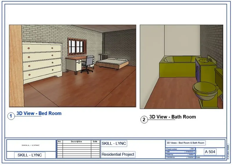
Thus the Challenge 4 is Done.