Creating Levels, Grids, Layout and model elements for a residential unit using REVIT
TASK 1:
BIM - BIM stands for Building Information Modelling.
BIM is a process for creating and managing information on a construction project across the project lifecycle. BIM is an modeling process that Architects, Engineers, and Contractors can use to collaborate on a building's Design, Construction, and Operation.
Features of BIM:
The main features of BIM are Coordination and Computation.
BENIFITS of BIM OVER A 2D CAD TOOLS:
- Real Time Modelling,
- Shorter Time Span to complete Projects,
- More Accuracy and Precise.
TASK 2:
AIM:
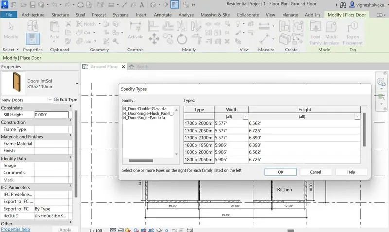
To Understand the concept of Categories, Families, Elements, Instances in Revit. And Load the Family and elements into the Revit Model.
PROCEDURE:
- In the Ribbon tool bar, Select the Category Door.
- Now the Ribbon tool Bar will be changed to Modify tab from Architectural Tab.
- In the Modify Tab ww will have an option called Load Family. Click on the Load Family and Select the Door Category.
- After selecting the Door category we will have multiple Door Families. Select the Door Family which we required for the model.
- After Selecting the Door Family, We will be opted for selecting the door elements. After selecting the elements click open.
- Thus the Category contains Familes and elements of the Door which we selected will be loaded in the model. for example Door is Category, Single Flush is Family, Sizes is Elements.
TASK 3:
AIM:
To Setup the Project Using Architectural Project Template. And save the Project file with the Project Information.
Procedure:
STEP 1: Opening and Saving the Project.
- Open the Revit file.
- In the Model Click on the New, Which open the dialogue box for opening the New Projects.
- Select the Architectural Template by Dropping the Template files. after that click Ok to Open the New Project.
- Click on the File to save the New Project to Appropriate Name (Residential Project 1).
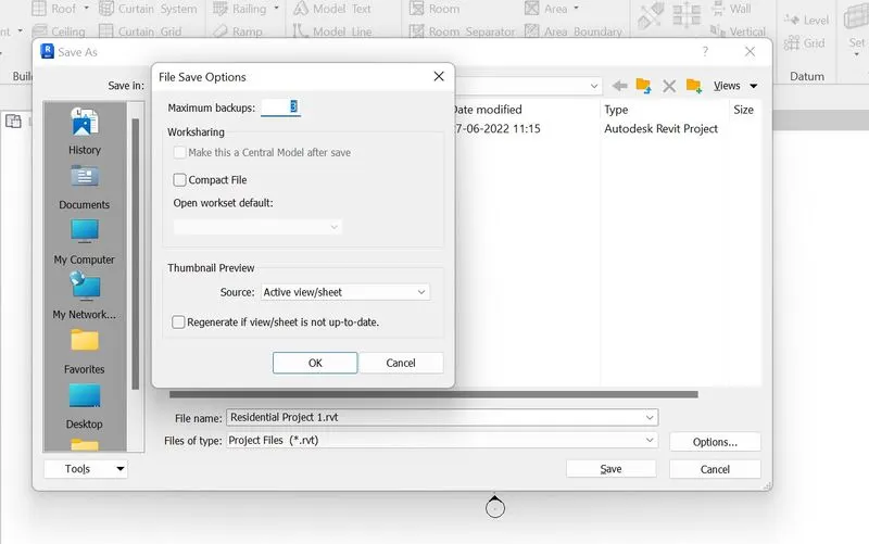
- After Entering the Project Name, Click on the Option Button in the bottom right of the Save dialogue box for the Saving the Project for Maximum Backup. As mentioed we will Set the Maximum backup of 3 and then click OK. And Agani OK to save the Project file.
STEP 2: Setting the Project Units.
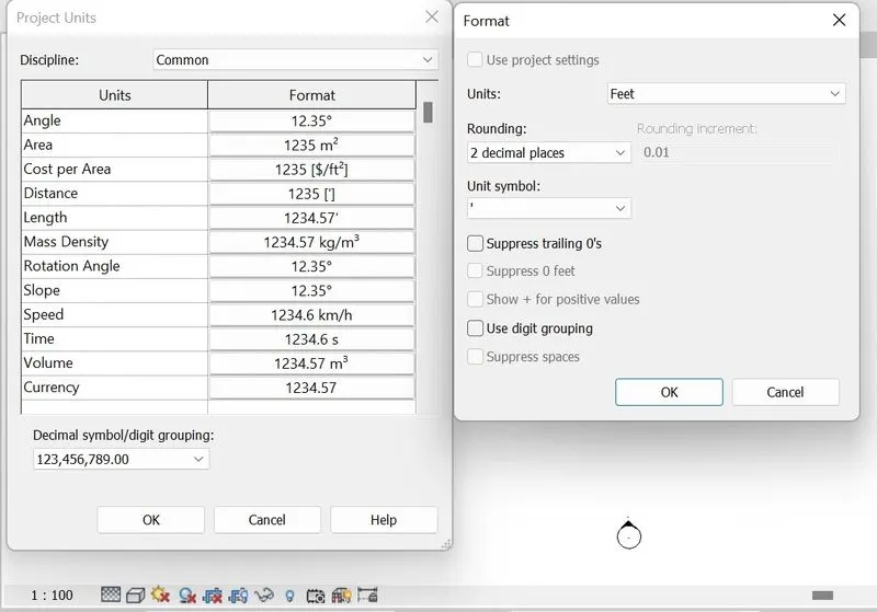
- Click on the Manage tab in the Ribbon toolbar, Under the Settings Icon in the Manage tab Select the Project Units Icon, and click that Icon.
- Now Project Units Tab will get open.
- We can choose our Project Units as per the clients requirements.
- Check the Discipline to be in common, Click on Length the Format Dialogue Box will get open. Here we can set the Projects Units, Units Symbol and Rounding Numbers. After Selecting click ok, Similarly Check for Area, Volume, etc., and click Ok.
- Finally the Project Units have been done.
STEP 3: Setting of Project Information.
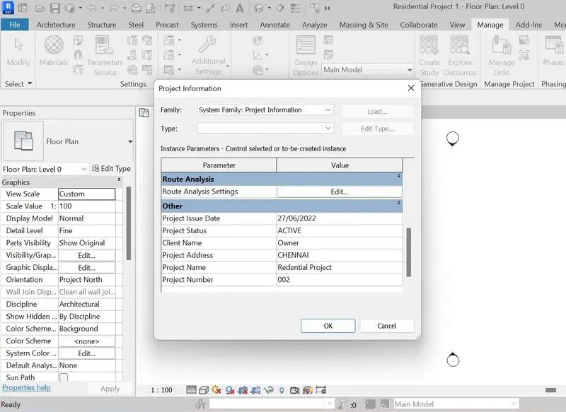
- In the same Manage tool bar, Select the the Project Information Icon under the Setting Tab.
- Project Information Dialogue box will appear, we can fill the Required Details about the Project as per the Clients Requirements.
- After Filling all the Required details click OK.
- Finally the Project Information Details as been entered.
- Click file icon on the top left Corner click the save button to save the project. Since the Maximnum number of backups were already entered while starting the Project now we can save the Project.
TASK 4:
AIM:
To Create the Levels and Grids With the given Values.
PROCEDURE:
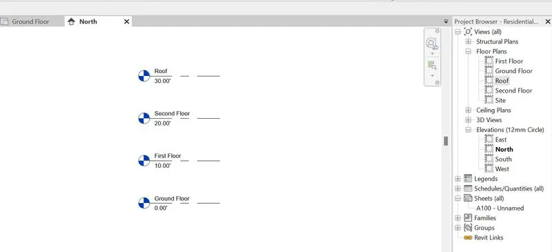
STEP 1: Creation of Levels with Feet as the Units.
- In the Project Browser, Under the Elevations - select any elevations (North/ East/ South/ West).
- In the Architectural Tab under Datum Tab, Click Levels.
- After Clicking Levels we will be having two options one is by Place a Level by Draw tool another one is Place a Level by using Pick lines.
- We can Place the levels by using Pick lines under the Offset 0f 10'.
- After Placing the Levels Change the Level Names as per the Project Requirement.
STEP 2: Creation of Grids.
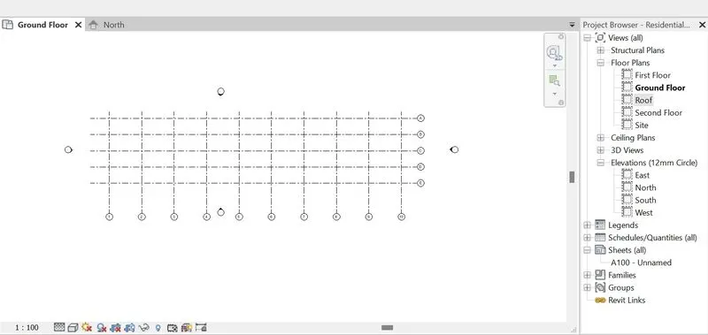
- Check we are in the workspace under the Ground floor Floor plan View.
- After that In the Architectural Tab under Datum Tab, Click Grids.
- Now we can Draw the Grid either Vertically or Horizantally as a begining.
- After Drawing we can use Pick Lines to Place the other Grids Parallely with regular interval of space.
- Do the same For the Perpendicular Direction also.
- But one more Additional Step is added here is which is renaming the Grid names. Because Grids should be of Alpha Numeric.
TASK 5:
AIM:
To model a conceptual layout of a residential unit.
PROCEDURE:
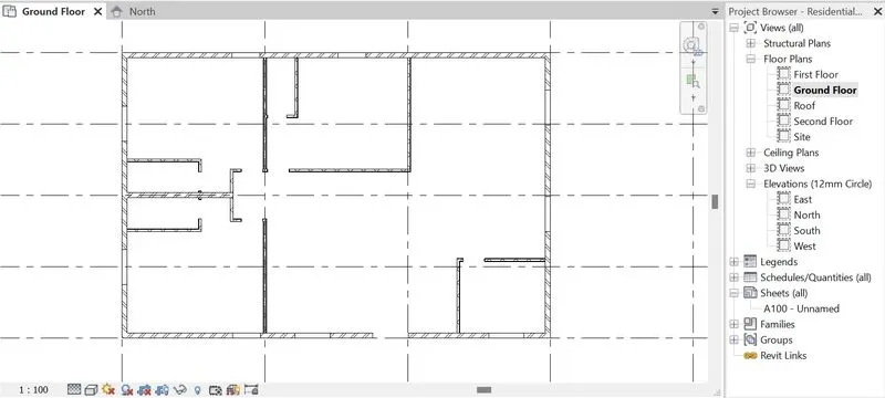
- In the Ground Floor under the Floor Plan View, Select the Wall catry in tha Architectural Tab.
- Draw a Wall of size 40' X 60' feet, as a builtup Area as layout.
- Let the outer wall thickness shall be 0.7'
- Place the partition Walls to place the rooms.
- Finally the 3BHK layout is done.
TASK : 6
AIM:
To include the Dimensions and the Components for the Residential Unit.
PROCEDURE:
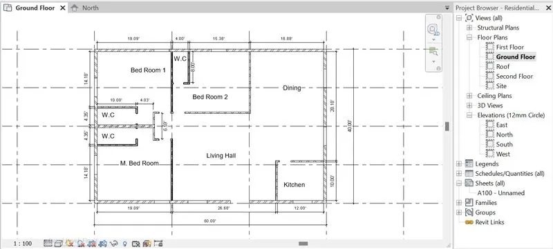
- From the annotate tab, under the Dimensions - select Either Linear nor Aligned Dimensions.
- Select the one end end of the Wall as a starting Dimension and Select the end of another Wall as a end point of the Dimension.
- Now we can enter the Room names by selecting the Text tab in the Annotation Tool bar.
- Click on the Text, place the Text in each rooms to add the names.
TASK : 7
AIM:
To include the Doors, Windows and the Components for the Residential Unit.
PROCEDURE:
- Select the Door Category in the Ribbon Tool bar under the Architecture tab.
- In the Door Category Select the Elements required for the Projects as per the requirements.
- After Selecting the Element Place the elements at the desired location of the walls.
- Select the Window Category in the Ribbon tool bar which is next to the Door Category.
- After Selecting the Window category Check for the different element in the Properties browser, If the required Element is not there check out in load Families in the same window category and Load the required Elements.
- After Loading the Window elements Place the windows in the wall at required Sill Height which we can change Sill Height in the Properties Browser after selecting the Window Element.
- Placing of Components such as tables, chairs, beds, etc., into the residential model.
- Select the Components Load the components from the Libraries like Furniture, Light Components., etc.,
- Select the Loded components from the properties Browser one by one to place the selected component in the approprite Position or Place.
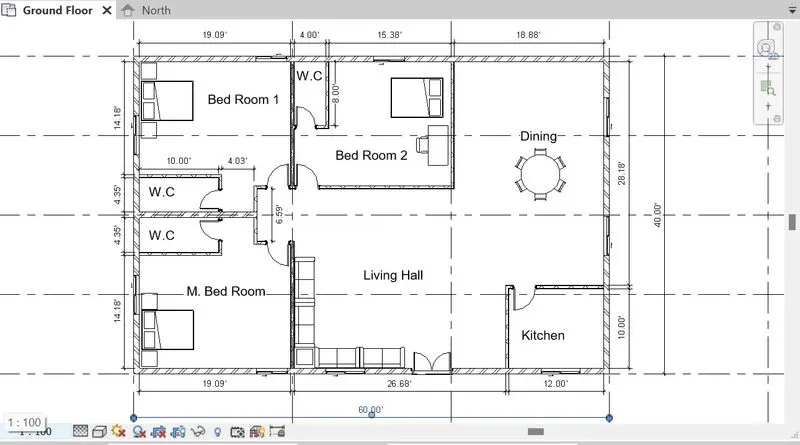
Thus the Challenge - 2 had been completed.