Introduction to REVIT concepts
AIM: Introduction to REVIT concepts
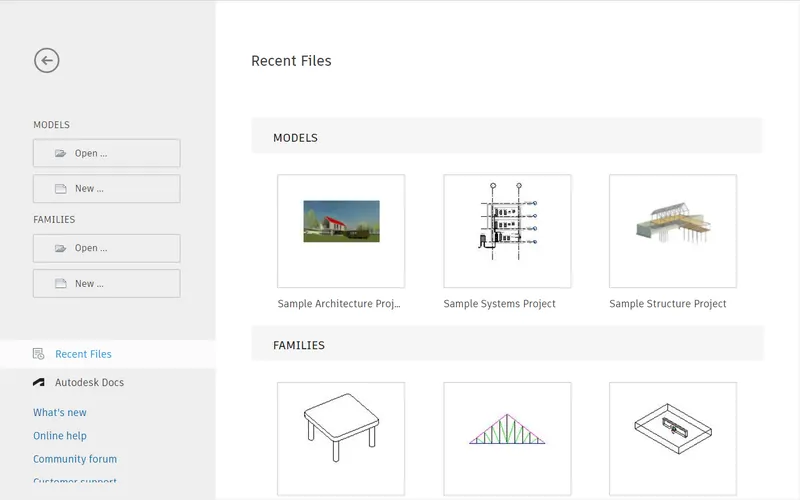
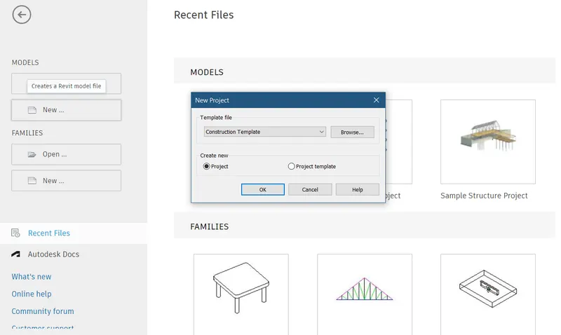
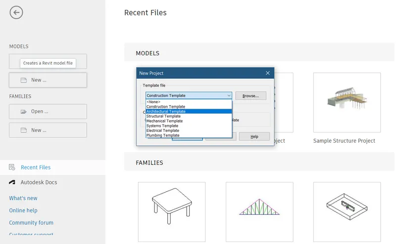
1) From the file menu, create a new project (Structural / Architectural / Construction template ) and name the project appropriately
Procedure:
- Open Revit Software in the computer
- Click on the file menu
- Now click on the new option from the list
- A window of new project opens
- Select the type template file u want to use
- for, example we select the architectural template
- Now select the project option in create new
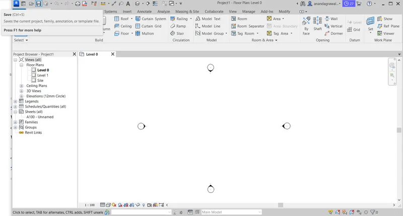
- Now revit opens
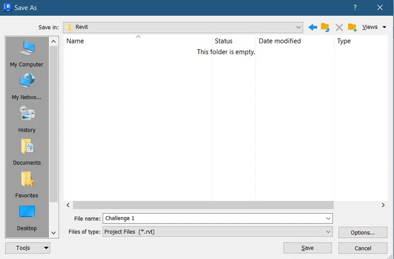
- Now use save option to save the file with a name
- Name the file as 'Challenge 1'
- Now thw file is created with a name
Result:
2) Save the new project file. Close and open using icons from file toolbar
Procedure:
- We have created a new file and saved the new project with the help of save option
- the name of the file is 'Challenge 1'
- Close the revit file with the saved name
- Now open the revit again
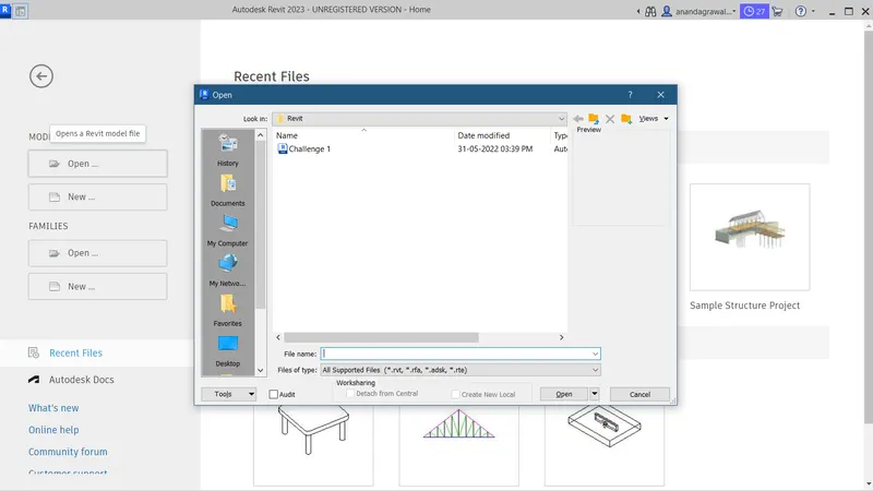
- Select the file option from thew menu
- Select the open option
- Search for the file to open
- Either select the file and select the open option or double click the file
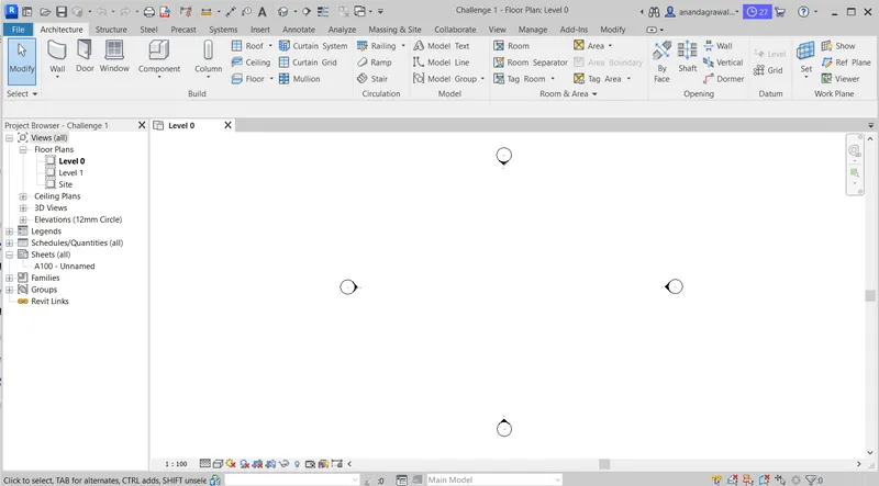
- The file will open with name challenge 1
Result:
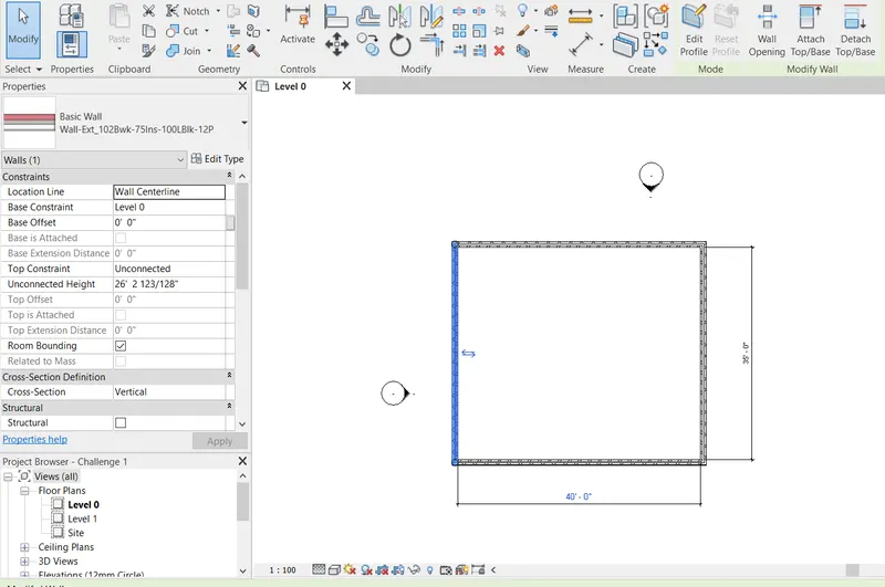
3) From the architecture/ structure toolbar familiarize with options to draw a wall. Create a rectangular layout of walls of about 40’-0” X 35’-0”
Procedure:
- Open the revit file with the name 'Challenge 1'
- Now goto architecture menu
- Click on the wall command in the architectural menu
- Now select the rectangle option in the modify tab
- Now Draw the wall of given dimensions (40'0" x 35'0")
- The wall is created
Result:

4) From the Annotate toolbar use the aligned option to add dimensions to the layout
Procedure
- Layout is completed in above question
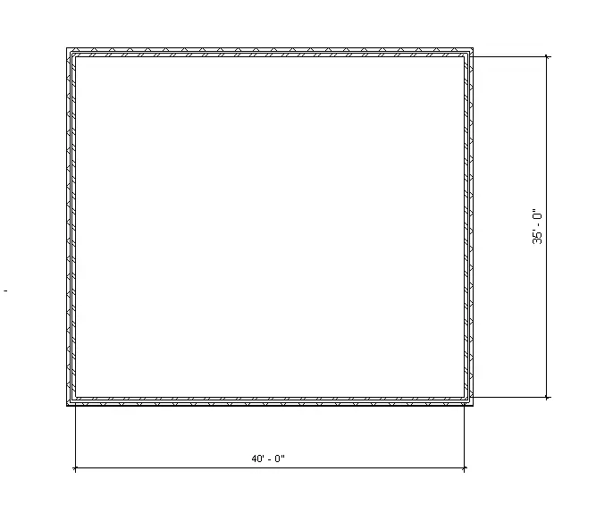
- Now we provide dimensions
- Goto annonate tab in the menubar
- Select the aligned dimensions option
- Select the first wall face and then the second wall face opposite to it
- Do the same for other side
Result:
5) Use the properties browser to switch to different wall types
Procedure:
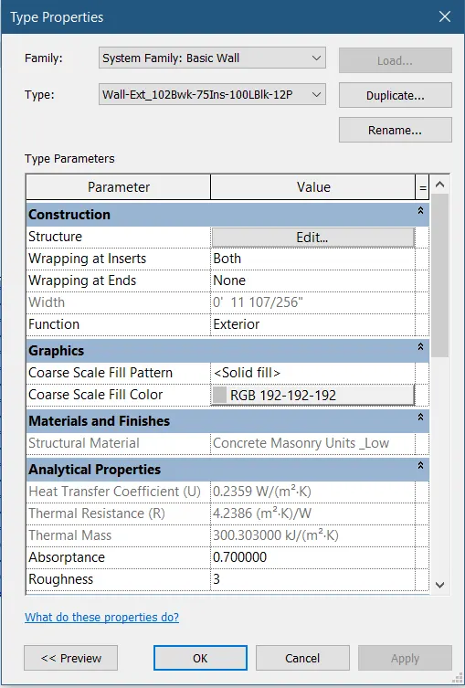
- To check the properties of the wall select the wall
- A properties menu is there in the left side of the wall
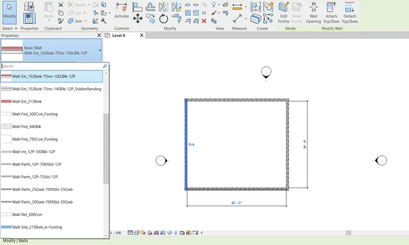
- One can edit the properties from the properties menu and also from the drop down list
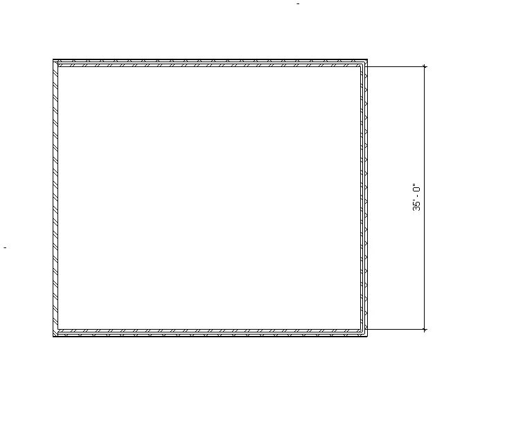
- Click on the wall type to which you want to change the current wall
- Now the wall is changed
Result:
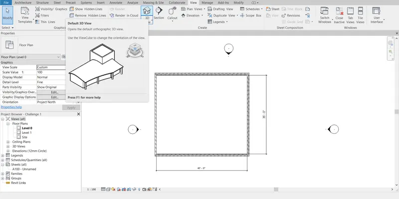
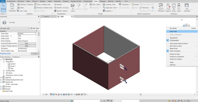
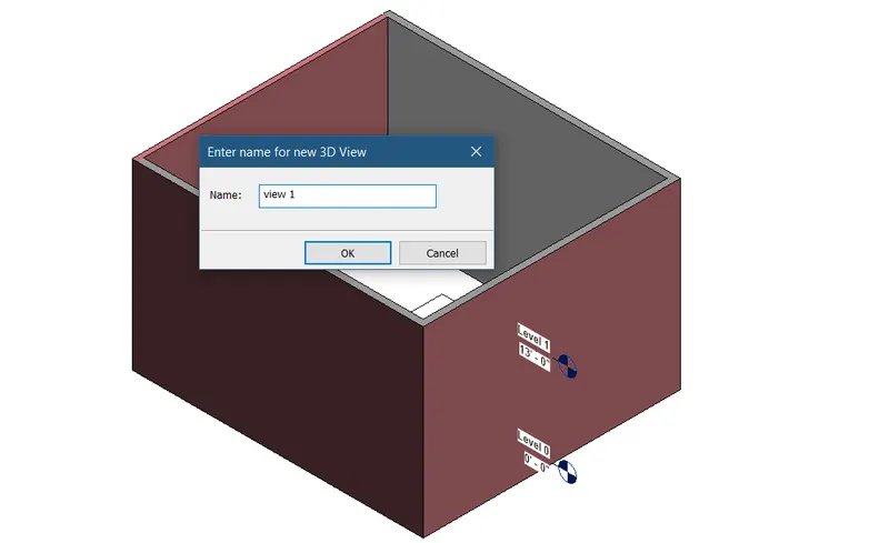
6) Create a 3D view from the view toolbar and save the view with the appropriate name
Procedure:
- Now to create a 3D view goto the view tab in the menu bar
- Select the 3D view option
- Set the view for the perfect oreintation
- Now right click on the cube and select the save view option
- Now provide a desired name to the view
- The saved views can be seen from the views tab
Result:
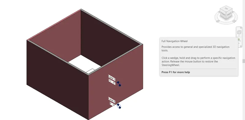
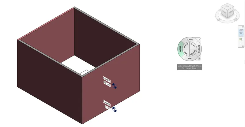
7) Navigate through the 3D model using the view cube. Orbit/pan through the model layout created
Procedure:
- Now Below the cube there is a tool bar with different tools
- We can navigate the drawing using the 3D cube
- From the bar below the cube we can pan/orbit/zoom etc.
Result:
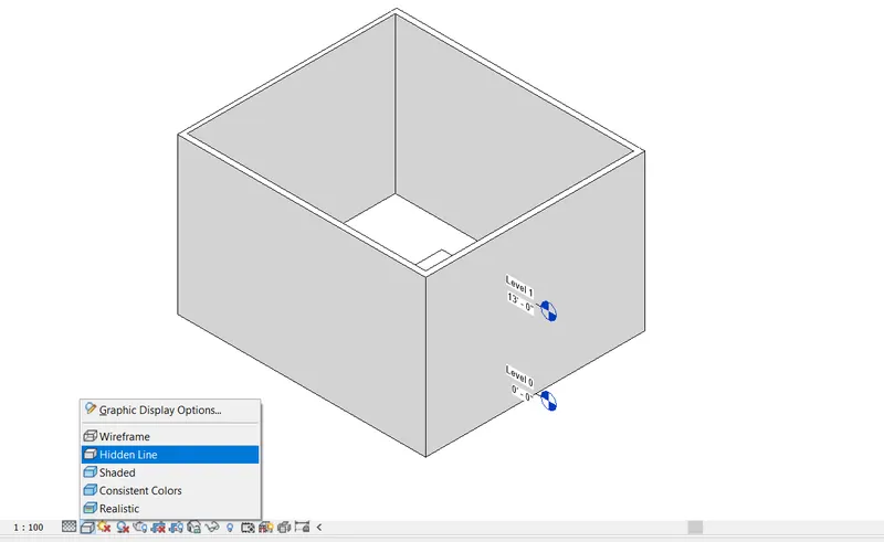
8) Use the visibility settings option below to switch model to shaded, realistic, hidden lines options
Procedure:
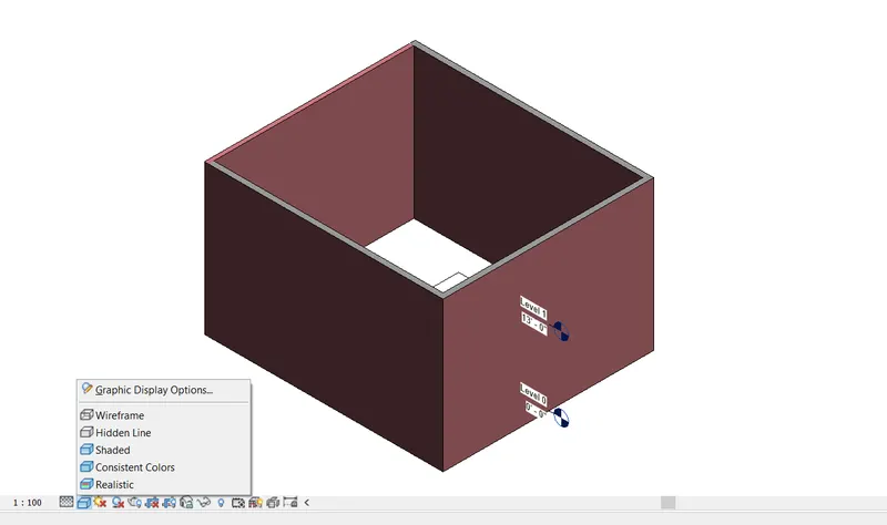
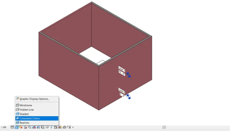
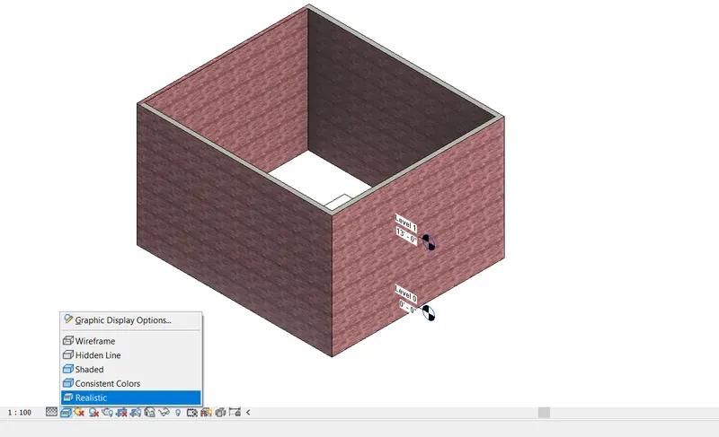
- To change the type of structural view select the cube icon which is given in the bottom most bar
- When clicked on that a list opens which has different type of views
- Select the desired view u want to see
Result:
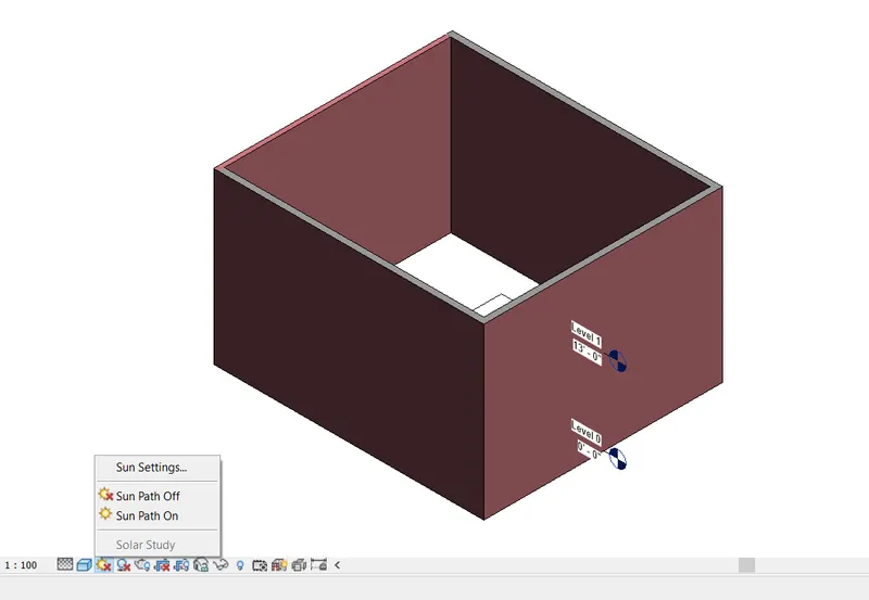
9) Turn the sun path on and off to view shadings in the layout created
Procedure:
- Sun path is used when we go for rendering option
- For the sun path we use the option of the sun given just beside to the view cube at the bottom most bar
- Click on the sun and it will ask to turn on or turn off the sun
- Click the turn on the sun and u will see the compass like thing appear
- It will show the direction
Result:

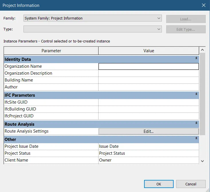
10) Use the Manage toolbar to enter project settings, project name, and project issue date (choose according to your convenience
Procedure:
- To add the project details, go to the manage tab of the menubar and click on the project information command icon.
- A dialog box will appear.
- Add the necessary details and press OK.
- Thus the project details are added.
- For more clarity have a look at the below snips.
Result:

11) What is the Analyze toolbar used in Revit? How it is beneficial for design and modeling
Ans:
The analyze toolbar is used to analyze the whole structure of the building. When one creates a structure there are many different kinds of forces, loads, and designs that are taken into consideration. A small failure can lead to the failure of the whole building. This analyze tab of the Revit software helps in analyzing if the structure is proper or not. Checks all the loads and gives the results for better designs as well and also gives the reasons why is the design not correct.
12) What are the links that Revit supports to be linked to the model?
Ans:
- Link Revit: Linking another revit model to current model
- Link CAD: Links CAD to current revit project. Linking is similar to having an xref in AutoCAD
- Point cloud: Links point cloud file (.rcp or rcs) into current project. It provides references for placing or editing model elements
- Link Topography : Links of existing topography to the current revit model. Topography created in software such as autodesk civil 3D
- DWF Markup: Links marked up DWF files into a revit project to see markups on corresponding sheets
- Link IFC: Links IFC file to current project. IFC enable interoperability between different software as it has international standards to import and export building elements
- Coordination model: Links NWD or NWC file to provide context for revit model
- Link PDF and Link Image to revit
13) Why do you need the Collaborate tab in Revit? How it supports modeling and its efficiency
Ans:
Collaboration tool offers users such as structural engineer and MEP engineers to work simultaneously. It enables cloud file, collaborate with it with multiple instances of independent files. It creates complete building model by bringing different models together. It enables to understand changes in the model and any conflicts occuring in the design when it is linked together. Thus it enables to design an optimized and efficient building model. Suppose to link revit file to current file (structural file), make a copy of current file and name it as MEP file. Link both the files and thus it enables to work on both files simultaneously.