Drafting of various geometries using Chamfer, Fillet tool in AutoCad
AIM:
Drafting of various geometries using Chamfer, Fillet tool in AutoCad
Figure:1
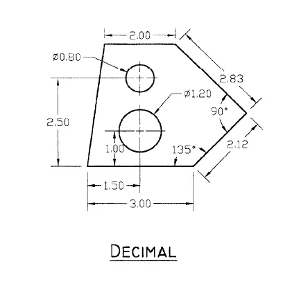
Procedure:
Steps:
- Type 'L' in the command box and press enter
- Specify first point: 1,1
- Specify next point: @3<0
- Specify next point: @2.12<45
- Specify next point: @2.83<135
- Specify next point: @2<180
- type close
- Type 'C' in the command box and press enter
- Specify center point for circle: 2.5,2
- Specify radius of circle: 0.6
- press enter
- Type 'C' in the command box and press enter
- Specify center point for circle: 2.5,3.5
- Specify radius of circle: 0.4
- press enter
- Give dimensions as per drawing using dimension command from the command bar
Result:
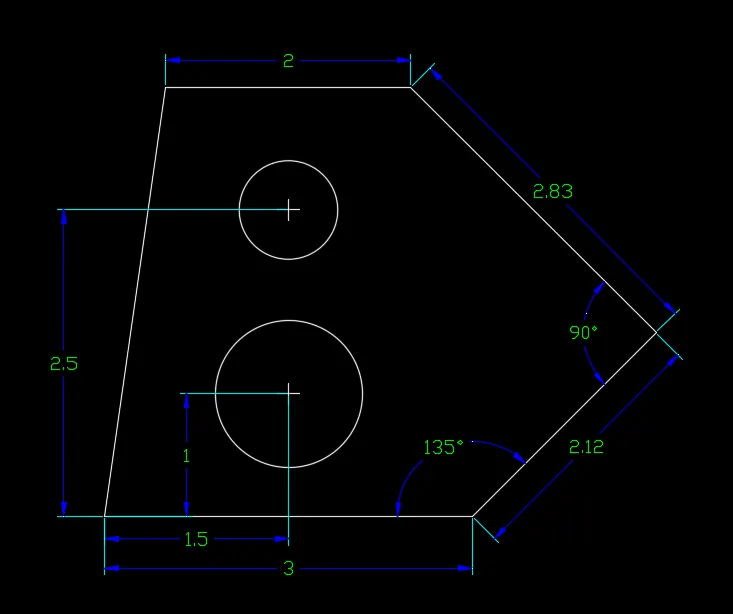
Figure 2:
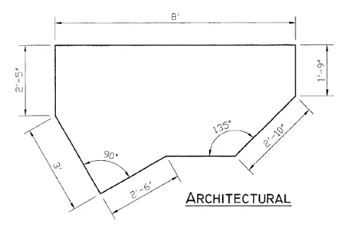
Procedure
Steps:
- Type 'UN' in the command box and press enter
- Select the Architectural Unit for length
- Type 'L' in the command box and press enter
- Specify first point: 2,6
- Specify next point: @8'<0
- Specify next point: @1'-9"<270
- Specify next point: @2'-10"<225
- Specify next point: @2'-4"<180
- Specify next point: @2'-6"<210
- Specify next point: @3'<120
- Type close and enter
- Type 'D' and press enter
- select modify option
- Select the unit format to Architectural In primary units
- Give dimensions as per drawing using dimension command from the command bar
Result:
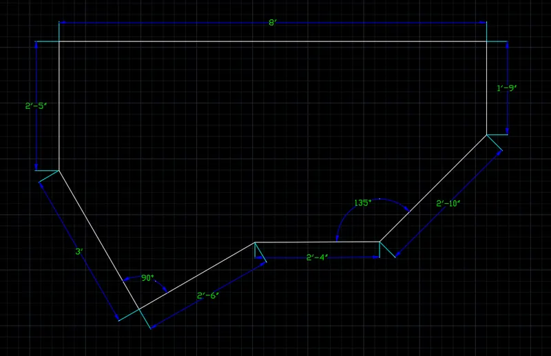
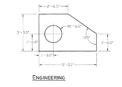
Figure 3:
Procedure:
Steps:
- Type 'UN' and press enter
- Select the unit system for length as 'Engineering'
- Type 'L' and press enter
- Specify first point: 1',1'
- Specify next point: @5'-0.1",0'
- Specify next point: @0',3'-3.0"
- Specify next point: @-5'-0.1",0'
- type close and enter
- Type 'cha' and enter
- Select distance option
- Specify first chamfer distance: 1'-9"
- Specify second chamfer distance: 2'-5.6"
- Select the lines and press enter
- Type 'c' and enter
- Specify the center point: 2'-3.0",2'-6.0"
- Select the diameter option
- Specify Diameter of circle: 1'-6.0"
- Type po and enter
- select the center point of circle and change the point type to plus from DDTYPE(PTYPE)
- Type 'd' and enter
- Select modify
- Select unit format as 'Engineering' in primary units option
- Give dimensions as per drawing using dimension command from the command bar
Result:
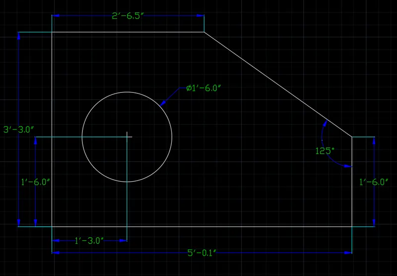
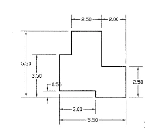
Figure 4:
Procedure:
Steps:
- Type 'L' and press enter
- Specify first point: 2,2
- Specify next point: @0,3
- Specify next point: @1,0
- Specify next point: @0,2
- Specify next point: @2.5,0
- Specify next point: @0,-3
- Specify next point: @2,0
- Specify next point: @0,-2.5
- Specify next point: @-2.5,0
- Specify next point: @0,0.5
- type close and press enter
- Give dimensions as per drawing using dimension command from the command bar
Result:
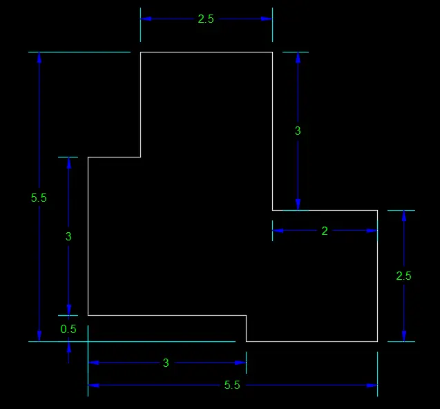
Figure 5:
Procedure:
Steps:
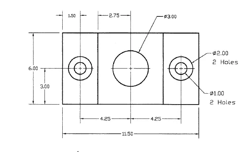
- Type 'L' and enter
- Specify first point: 2,2
- Specify next point: @11.50,0
- Specify next point: @0,6
- Specify next point: @-11.50,0
- type close and enter
- Type 'L' and enter
- Specify first point: 5,2
- Specify next point: @0,6
- press enter
- Type 'L' and enter
- Specify first point: 10.5,2
- Specify next point: @0,6
- press enter
- Type po and enter
- Specify a point: 3.5,5
- repeat po command and give point: 12,5
- Type c and enter
- Specify center point for circle: 3.5,5
- select diameter option
- Specify diameter of circle: 2
- Type c and enter
- Specify center point for circle: 3.5,5
- select diameter option
- Specify diameter of circle: 1
- Type c and enter
- Specify center point for circle: 12,5
- select diameter option
- Specify diameter of circle: 2
- Type c and enter
- Specify center point for circle: 12,5
- select diameter option
- Specify diameter of circle: 1
- Type c and enter
- Specify center point for circle: 7.75,5
- select diameter option
- Specify diameter of circle: 3
- Give dimensions as per drawing using dimension command from the command bar
Result:
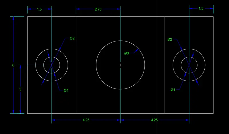
Figure 6:
Procedure:
Steps:
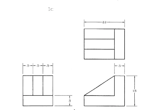
- First fig:
- Type 'L' and enter
- Specify first point: 2,2
- Specify next point: @1.5,0
- Specify next point: @0,1.5
- Specify next point: @-1.5,0
- type close and enter
- Type 'L' and enter
- Specify first point: 2,2.5
- Specify next point: @1.5,0
- press esc
- Type 'L' and enter
- Specify first point: 2.5,2.5
- Specify next point: @0,1
- press esc
- Type 'L' and enter
- Specify first point: 3,2.5
- Specify next point: @0,1
- press esc
- Type 'L' and enter
- Second fig:
- Type 'L' and enter
- Specify first point: 5,2
- Specify next point: @2,0
- Specify next point: @0,1.5
- Specify next point: @-0.5,0
- Specify next point: @0,-1
- Specify next point: @-1.5,0
- Type close and enter
- Type 'L' and enter
- Specify first point: 5,2.5
- Specify next point: 6.5,3.5
- press esc
- Type 'L' and enter
- Third fig:
- Type 'L' and enter
- Specify first point: 5,4.5
- Specify next point: @2,0
- Specify next point: @0,1.5
- Specify next point: @-2,0
- type close and enter
- Type 'L' and enter
- Specify first point: 6.5,4.5
- Specify next point: @0,1.5
- Type 'L' and enter
- Specify first point: 5,5
- Specify next point: @1.5,0
- Type 'L' and enter
- Specify first point: 5,5.5
- Specify next point: @1.5,0
- Type 'L' and enter
- Give dimensions as per drawing using dimension command from the command bar
Result:
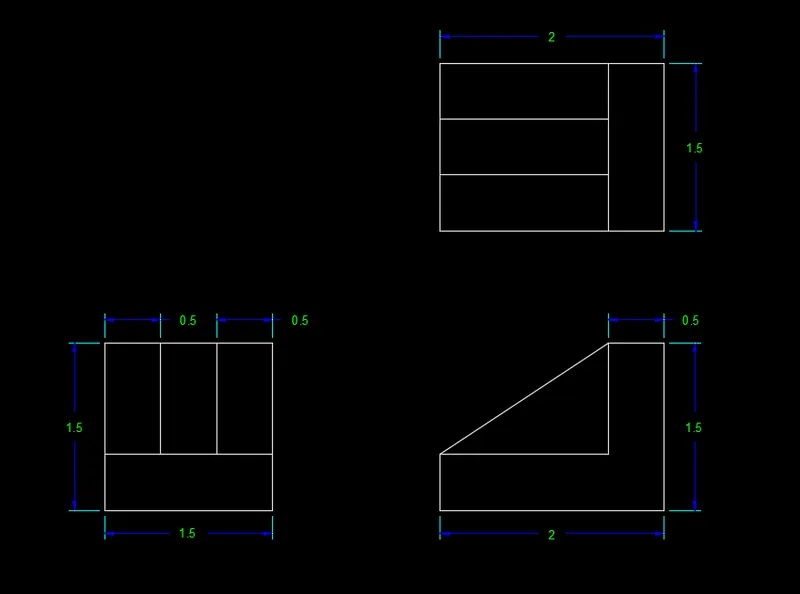
Figure 7:
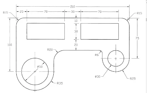
Procedure:
Steps:
- Type 'L' and enter
- Specify first point: 30,150
- Specify next point: @210,0
- Specify next point: @0,-75
- Specify next point: @-50,0
- Specify next point: @0,15
- Specify next point: @-90,0
- Specify next point: @0,-40
- Specify next point: @-70,0
- type close
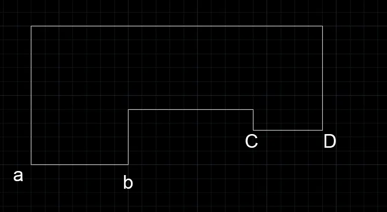
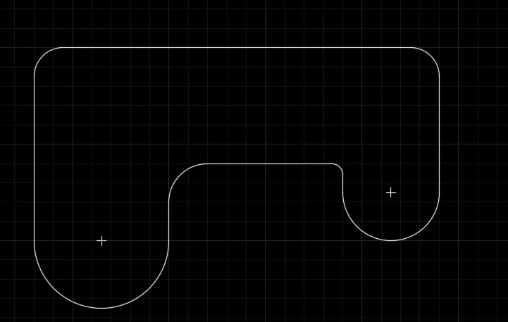
- Use trim tool to trim lines between a-b &c-d
- Type fillet and enter
- Select radius option
- Specify radius of fillet: 35
- Select the lines of a and b
- press enter
- Type fillet and enter
- Select radius option
- Specify radius of fillet: 25
- Select the lines of c and d
- press enter
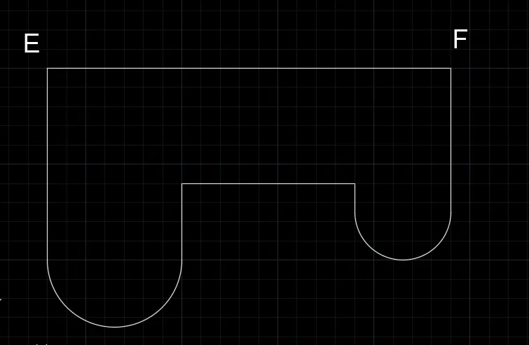
- Use fillet command and give fillets at e, f, g & h
- At E & F fillet radius: 15
- At G fillet radius: 20
- At H fillet radius: 6
- Select multiple point option from draw ribbon
- Specify a point: 65,50
- Specify a point: 215,75
- Type c and enter
- Specify center point of circle: 65,50
- Select the diameter option
- Specify diameter of circle: 50
- Type c and enter
- Specify center point of circle: 215,75
- Select the diameter option
- Specify diameter of circle: 30
- Type rec and enter
- Specify first corner point: 50,110
- Select dimensions
- Specify length for rectangle: 70
- Specify width for rectangle: 30
- Specify other corner point: 120,140
- Type rec and enter
- Specify first corner point: 150,110
- Select dimensions
- Specify length for rectangle: 70
- Specify width for rectangle: 30
- Specify other corner point: 220,140
- Give dimensions as per drawing using dimension command from the command bar
Result:
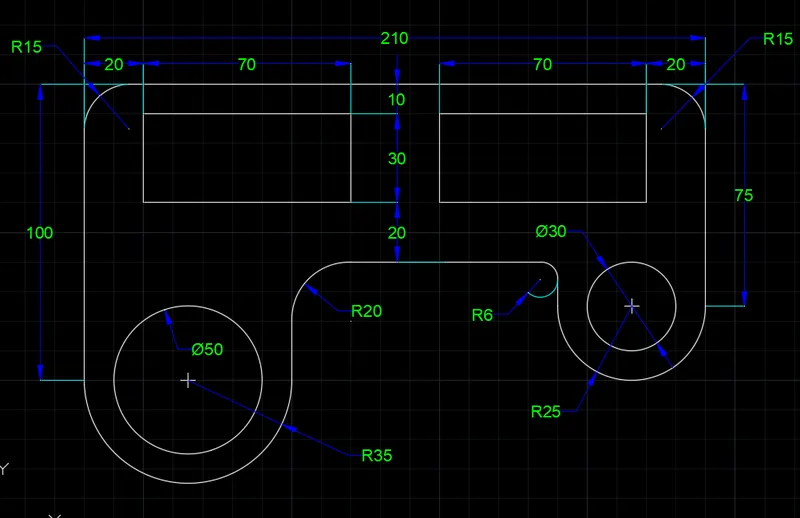
Figure 8:
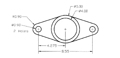
Procedure:
Steps:
- Select the multiple point option from draw ribbon
- specify a point: 3.725,5
- Specify a point: 8,5
- Specify a point: 12.275,5
- Type 'c' and enter
- Specify center point for circle: 3.725,5
- Select diameter option
- Specify diameter of circle: 0.90
- press enter
- Type 'c' and enter
- Specify center point for circle: 3.725,5
- Specify radius of circle: 0.90
- press enter
- Type 'c' and enter
- Specify center point for circle: 8,5
- Select diameter option
- Specify diameter for circle: 5
- press enter
- Type 'c' and enter
- Specify center point for circle: 8,5
- Select diameter option
- Specify diameter for circle: 4
- press enter
- Type 'c' and enter
- Specify center point for circle: 8,5
- Select diameter option
- Specify diameter for circle: 5
- press enter
- Type 'c' and enter
- Specify center point for circle: 12.275,5
- Select diameter option
- Specify diameter of circle: 0.90
- press enter
- Type 'c' and enter
- Specify center point for circle: 12.275,5
- Specify radius of circle: 0.90
- press enter
- Select the tangent option from osnap settings
- Type 'L' and Draw tangents connecting with outer circles
- Use trim option to trim the inner portion of side circles
Result:
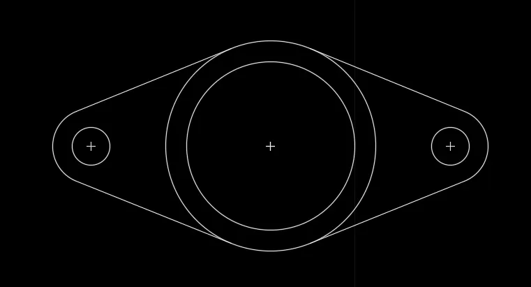
- Give dimensions as per drawing using dimension command from the command bar
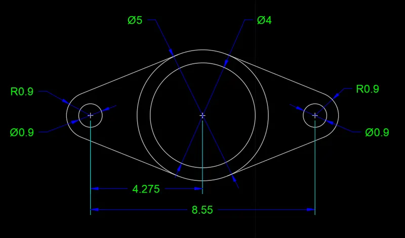
Figure 9:
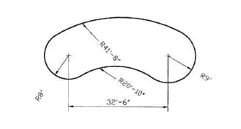
Prcedure:
Steps:
- Type 'UN' and press enter
- Select the unit system for length as 'Engineering'
- Select multiple points option from draw ribbon
- specify a point: 20',15'
- Specify a point: 52'-6",15'
- Type 'c' and enter
- Specify center point for circle: 20',15'
- Specify radius of circle: 8'-0"
- press enter
- Type 'c' and enter
- Specify center point for circle: 52'-6",15'
- Specify radius of circle: 9'-0"
- press enter
- Use Arc command and make 2 Arcs connecting both circle with different radius
- Radius of upper arc: 41'-8"
- Radius of bottom arc: 20'-10"
- Use trim tool to trim the inner portion of circle
- Give dimensions as per drawing using dimension command from the command bar
Result:
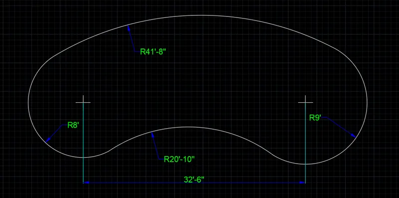
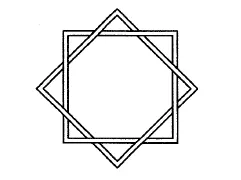
Figure 10:
Procedure:
Steps:
- Select the polygon command
- Enter the number of side: 4
- Specify center point of polygon : 20,20
- Select Inscreibed in circle
- Specify radius of circle: 10
- Use offset command and offset the polygon at a distance of 1 unit
- select rotate option from home tab
- Select objects
- Select the copy option
- Specify rotation angle: 45
- use trim tool to trim lines as shown in fig
Result:
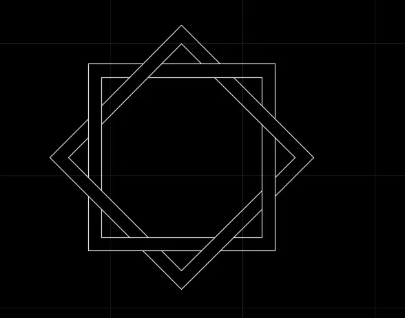
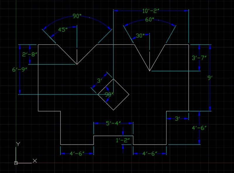
Figure 11:
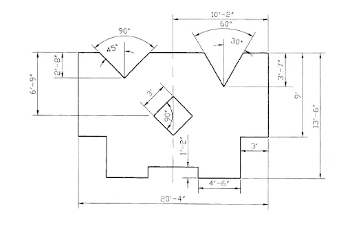
Procedure:
Steps:
- Type 'UN' in the command box and press enter
- Select the Architectural Unit for length
- Type l and enter
- Specify first point: 3',16'
- Specify next point: @0',-9'
- Specify next point: @3',0'
- Specify next point: @0',-4'-6"
- Specify next point: @4'-6",0'
- Specify next point: @0',1'-2"
- Specify next point: @5'-4",0'
- Specify next point: @0',-1'-2"
- Specify next point: @4'-6",0'
- Specify next point: @0',4'-6"
- Specify next point: @3',0'
- Specify next point: @0',9'
- Type close
- Type l and enter
- specify first point: 8'-3",16'
- Specify next point: @0',-2'-8"
- press esc
- Type l and enter
- specify first point: 18'-1",16'
- Specify next point: @0',-3'-7"
- press esc
- Now use xline option and make lines at an angle of 45 and 30
- Now use trimk option to trim the unwanted lines
- Use rectangle option to make a square of 3' at the center of the figure at an angle of 45 degree
- Give dimensions as per drawing using dimension command from the command bar
Result: