Creating a Floor plan, Footing detail and Isometric view using AutoCad
AIM:
Creating a Floor plan, footing detail and isometric view using AutoCAD.
Part I: C.S. of Load Bearing wall over Spread Footing
Procedure:
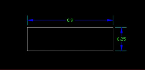
Step 1:
- Type 'rec' in the command box and press enter
- specify the first corner point of rectangle (1.5,0.2)
- Click D for dimensions
- specify length = 0.9
- specify width = 0.25
- Press enter
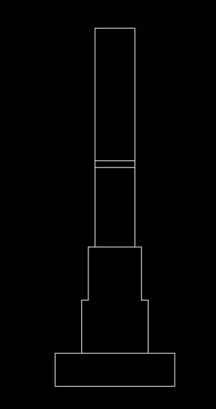
Step 2:
- Type 'PL' or 'PLINE' in the command box
- Specify start point 1.7,0.45
- Specify next point - @0,0.4
- Specify next point - @0.05,0
- Specify next point - @0,0.4
- Specify next point - @0.05,0
- Specify next point - @0,1.65
- Specify next point - @0.3,0
- Specify next point - @0,-1.65
- Specify next point - @0.05,0
- Specify next point - @0,-0.4
- Specify next point - @0.05,0
- Specify next point - @0,-0.4
- Press enter
- type L in command box
- Specify the first point - 1.8,1.25
- Specify next point - @0.3,0
- Press enter
- type L in the command box
- Specify first point - 1.8,1.85
- Specify next point - @0.3,0
- press enter
- type L in the command box
- Specify first point - 1.8,1.9
- Specify next point - @0.3,0
- press enter
Step 3:
- Type 'pl' and press enter
- Specify start point - 1.75,1.1
- Specify next point - @-1.15,0
- Specify next point - @0,0.15
- Specify next point - @0.3,0
- Specify next point - @0,0.15
- Specify next point - @0.3,0
- Specify next point - @0,0.15
- Specify next point - @0.3,0
- Specify next point - @0,0.15
- Specify next point - @0.3,0
- Press enter
- Type L in the command box
- Specify the first point - 2.15,1.25
- Specify next point - @1,0
- Specify next point - @0,0.6
- Specify next point - @-1.05,0
- press enter
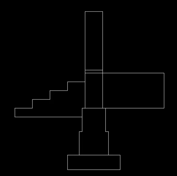
Step 4:
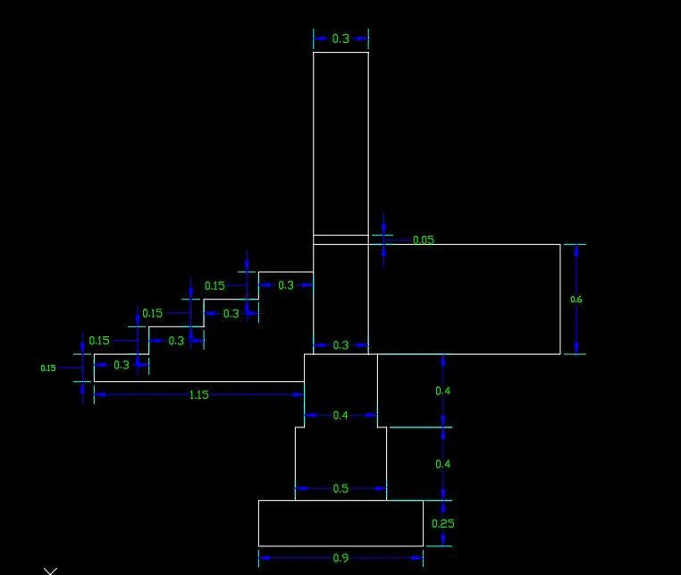
Give dimensions as per drawing using dimension command from the command bar
The C.S of load bearing wall over spread footing is completed
Part II: C.S. of Isolated Footing
Step 1:
- Type 'rec' and press enter
- specify firstcorner point 1,0.5
- select dimensions
- enter the length - 1.0
- enter the width - 0.4
- specify the other corner point - 2,0.9
- Type chamfer in the command box and press enter
- select the distance option
- specify first chamfer distance - 0.15
- specify second chamfer distance - 0.38
- select the lines and press enter
- Do the same process again for other side
- Now use the trim option to trim the upper most line
- Type l in the command box and press enter
- Specify first point - 1.38,0.9
- Specify next point - @0,1.60
- Specify next point - @0.24,0
- Specify next point - @0,-1.6
- press esc
- Type L in the command box and press enter
- Specify first point - 1.42,2.5
- Specify next point - @0,-1.96
- Specify next point - @-0.38,0
- Specify next point - @0,0.04
- press esc
- type mirror in the command box and select the objects to mirror and press enter
- Specify first point of mirror line - 1.5,0.5
- Specify second point of mirror line - 1.5,2.5
- press enter
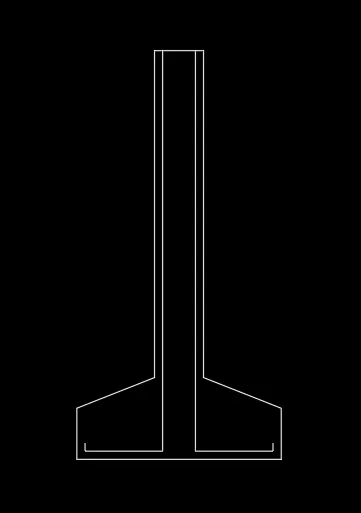
Step 2:
- Type L in the command box and press enter
- Specify first point - 1.42,2.3
- Specify next point - @0.16,0
- press esc
- Type 'o' or offset and press enter
- Specify the offset distance 0.2
- select the object and offset it in negative y axis using mouse
- Repeat the above step 7 more times
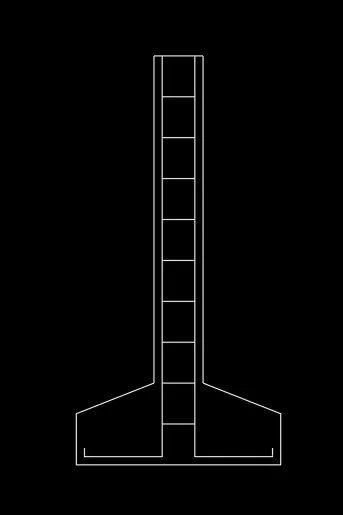
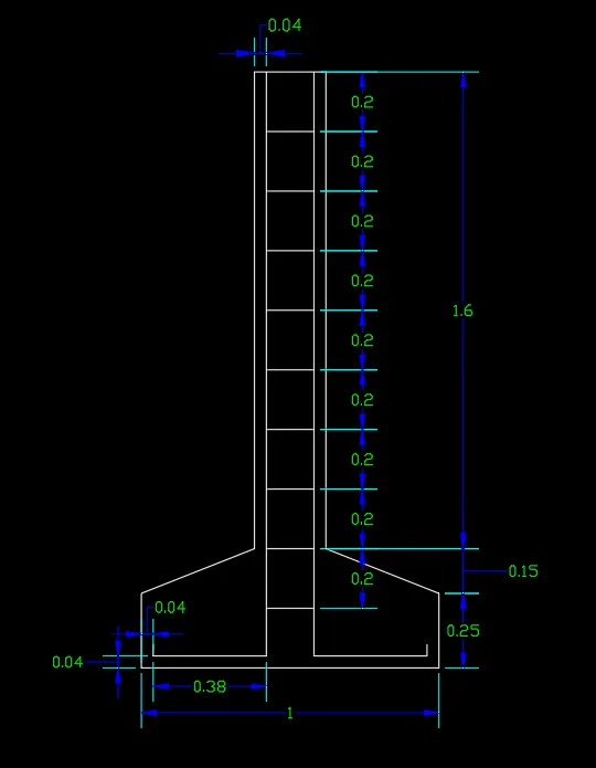
Step 3:
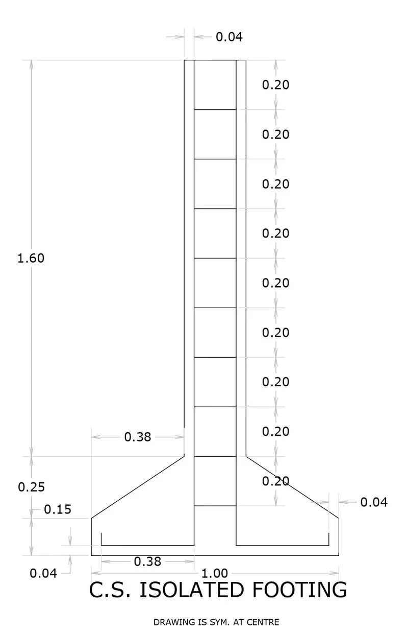
Give dimensions as per drawing using dimension command from the command bar
The C.S. Of Isolated Footing is created
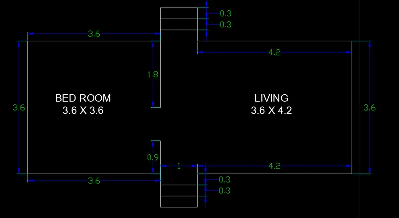
Part III: Line Diagram of Two Bedroom Building
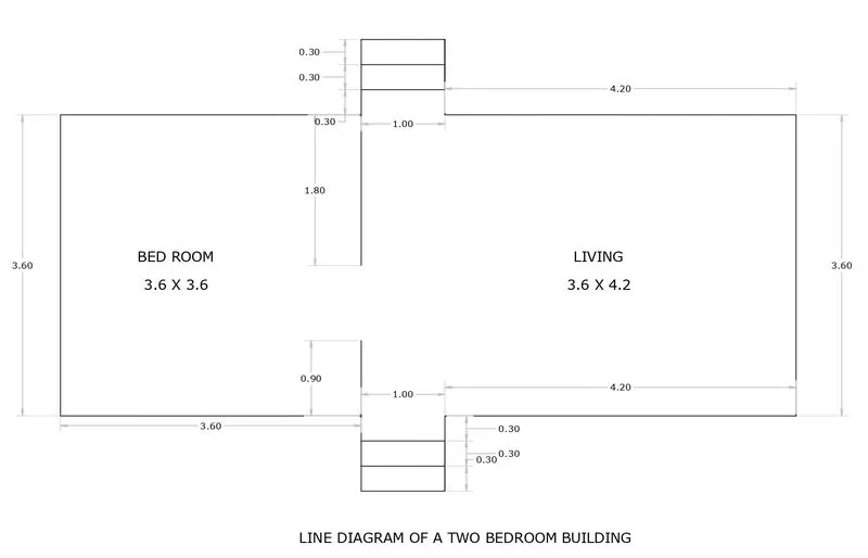
Step 1:
- Type L in the command box and press enter
- Specify first point - 4.6,2.4
- Specify next point - @0,-0.9
- Specify next point - @-3.6,0
- Specify next point - @0,3.6
- Specify next point - @3.6,0
- Specify next point - @0,-1.8
- press esc
- Type L and press enter
- Specify first point - 5.6,1.5
- Specify next point - @4.2,0
- Specify next point - @0,3.6
- Specify next point - @-4.2,0
- Press esc

Step 2:
- Type PL and press enter
- Specify first point - 4.6,1.5
- Specify next point - @0,-0.3
- Specify next point - @1,0
- Specify next point - @0,0.3
- Press esc
- Type CO and press enter
- Select the poliline and press enter
- Use mouse to copy it 2 times below
- Do the same process for other side
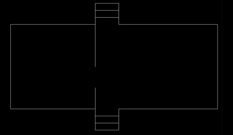
Step 3:
Give dimensions as per drawing using dimension command from the command bar
The Line diagram of two Bedroom Building is created
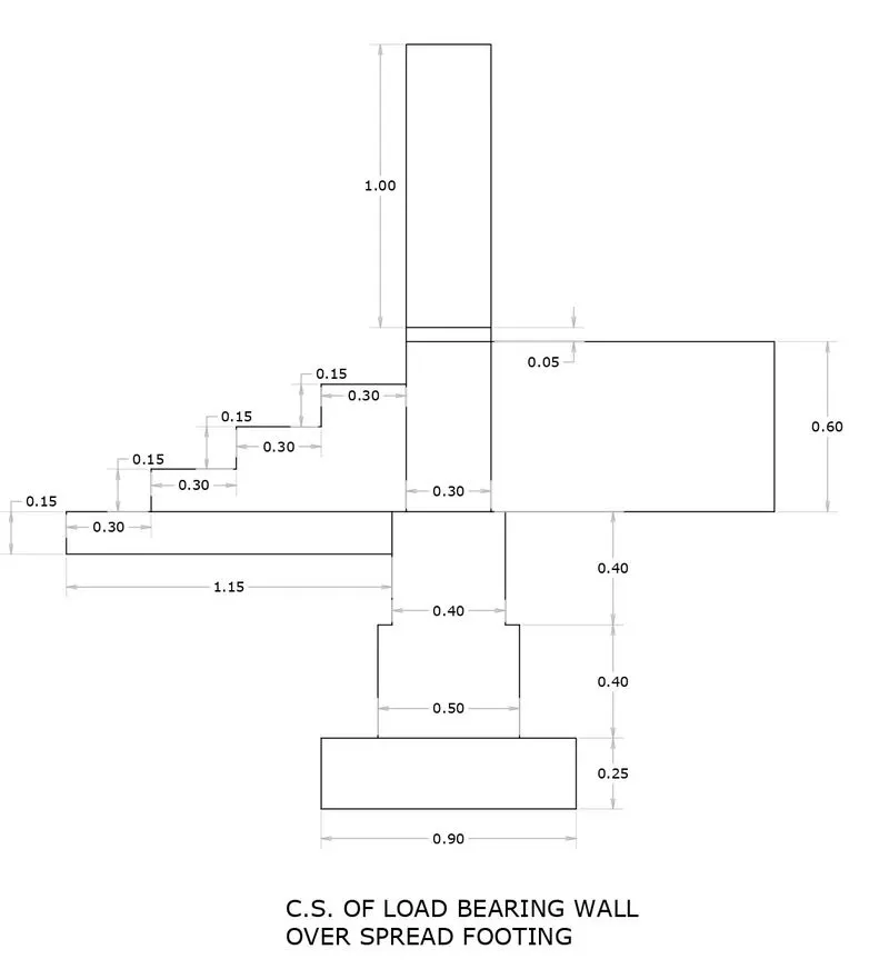
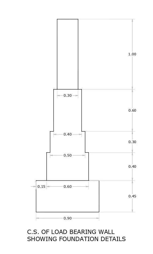
Part IV: C.S. of Load bearing wall showing Foundation details
Step 1:
- Type L in the command line and press Enter.
- Specify First point: 1,0.3
- Specify next point: @0,.45
- Specify next point:@.15, 0
- Specify next point: @0,.40
- Specify next point: @.05, 0
- Specify next point: @0,.30
- Specify next point: @.05, 0
- Specify next point: @0,.60
- Specify next point: @.05, 0
- Specify next point: @0,1
- Specify next point: @.30,0
- Specify next point: @0, -1
- Specify next point: @.05, 0
- Specify next point: @0,-.60
- Specify next point: @.05, 0
- Specify next point: @0,-.30
- Specify next point: @.05,0
- Specify next point: @0,-.30
- Specify next point: @.05,0
- Specify next point: @0,-.40
- Specify next point: @.15,0
- Specify next point: @0,-.45
- Specify next point: @-.90, 0
- Type L in the command box and press enter
- Specify first point: 1.15,0.75
- Specify next point: @0.60,0
- press enter
- Type L in the command box and press enter
- Specify first point: 1.3,2.05
- Specify next point - @0.3,0
- press enter
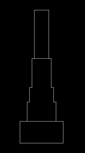
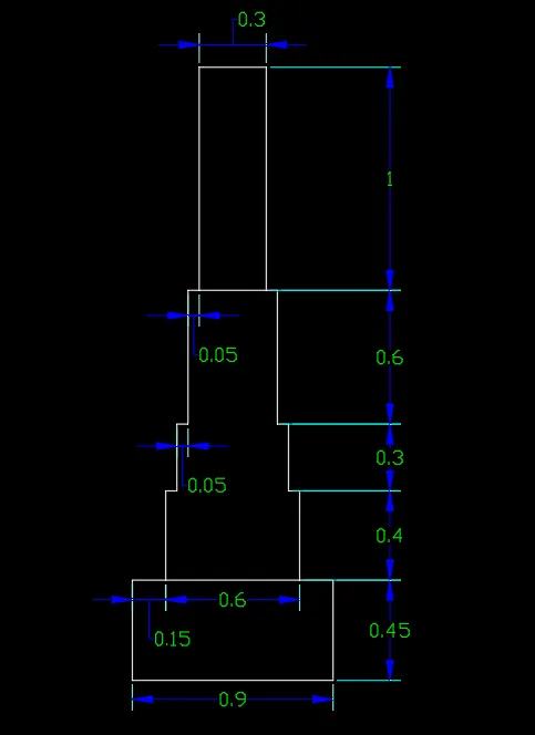
Step 2:
Give dimensions as per drawing using dimension command from the command bar
The C.S. of Load bearing wall showing Foundation details is created
Part V: Isometric view of steps
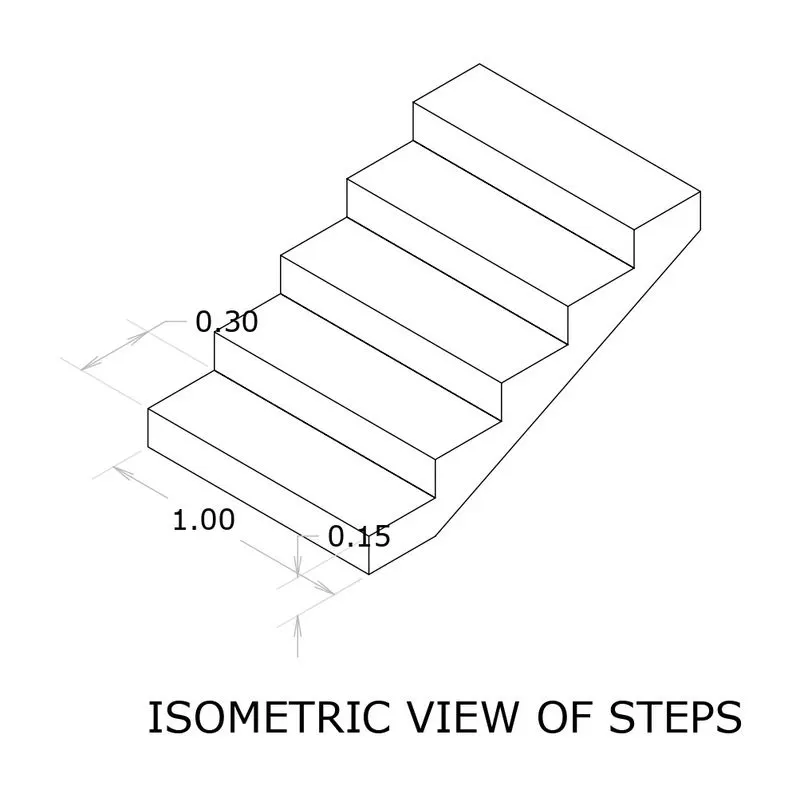
Step 1:
- Type DS in the command line and press enter.
- Unpick snap on and grid on options
- Tick on isometric snap in snap type.
- This will activates the isometric screen.
- Type rec press enter
- Select thickness in modes
- Specify thickness of rectangle: 0.15
- Specify first corner point: 0.5,0.5
- Enter lenght:0
- Enter width: 1
- Type l and press enter
- Specify first point : 0.5,1.5,0.15
- Specfy next point: @0.3,0
- Specfy next point: @0,-1
- Specfy next point: @-0.3,0
- Press enter
- Type CO and press enter
- Select whole object
- Specify the base point: 0.5,0.5,0
- Copy the object 4 times using the cursor
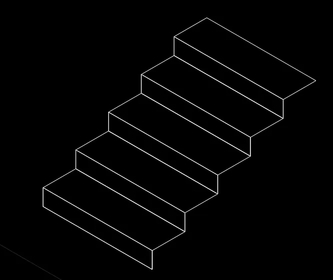
Step 2:
- Type L in the command box and press enter
- Specify first point: 0.5,0.5,0
- Specify the next point: @0.3,0
- press esc
- Type L in the command box and press enter
- Specify first point: 2,0.5,0.75
- Specify next point: @0,0,-0.15
- Now using line command join the two points which are open
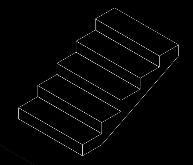
Step 3:
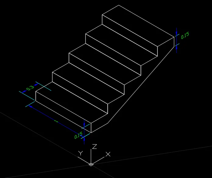
Give dimensions as per drawing using dimension command from the command bar
Isometric View of steps is created
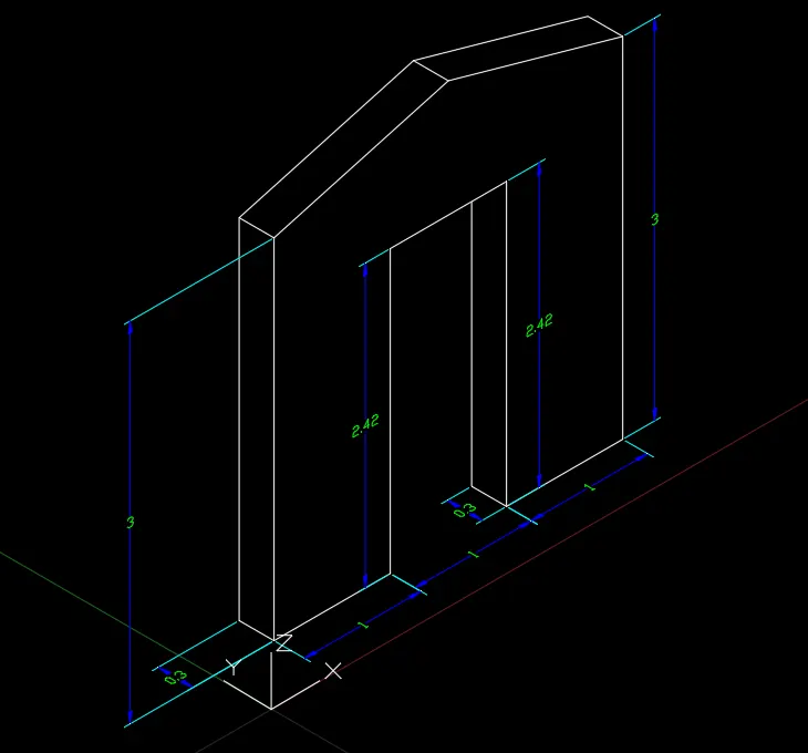
Part VI: Isometric view of Gable Wall
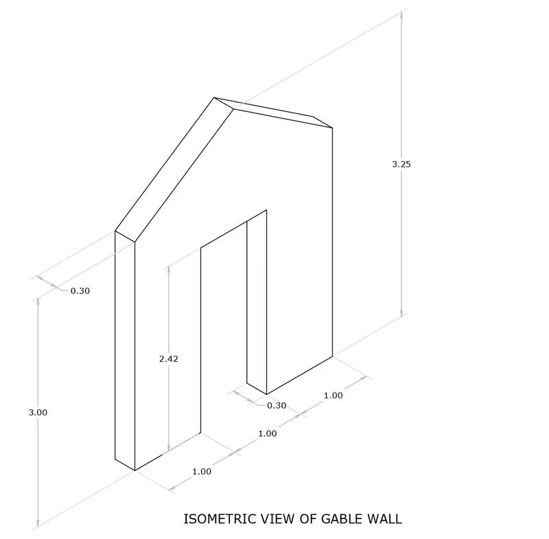
Step 1:
- Type DS in the command line and press enter.
- Unpick snap on and grid on options
- Tick on isometric snap in snap type.
- This will activates the isometric screen. press Enter.
- Type L in the command line and
- Specify the start point 0.5,0.5.
- Take isoplane left
- Specify the next point.30,curser towards NW
- Specify the next point:3, curser towards N
- Specify the next point:.30, curser towards SE
- Specify the next point.3, curser towards E
- Type L in the command line and press Enter.
- Specify the start point a0.5,0.5
- Take isoplane right
- Specify the next point:1,curser towards NE
- Specify the next point:2.42,curser towards N
- Specify the next point:1,curser towards NE
- Specify the next point 2.42,curser towards E
- Specify the next point:1,curser towards NE
- Specify the next point:3,cursor towards N
- press enter
- type L and press enter
- Select the mid pot of object
- give dimension 4 towards N
- Use copy option and copy the line at point : 0.5,0.5,3
- to the points : (3.5,0.5,3) , (2.5,0.5,0) & (2,0.5,3.42)
- Join the lines using line command
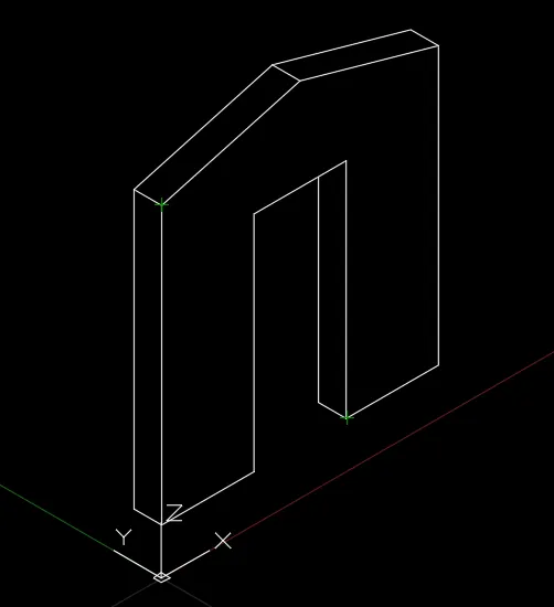
Step 2:
Give dimensions as per drawing using dimension command from the command bar
Isometric view of gable wall is created