Introduction to REVIT concepts
1.From the file menu, create a new project (Structural / Architectural / Construction template ) and name the project appropriately
Aim
To create a New Project by using Architectural Template and giving appropriate name to the project.
Procedure
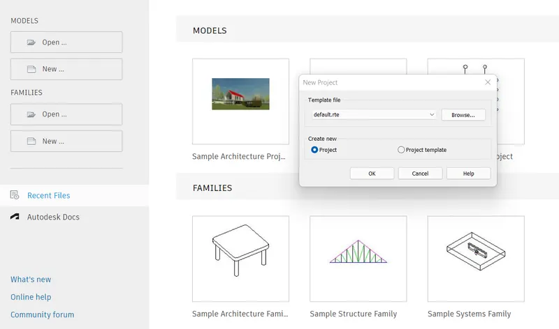
Double click the Revit software a screen will appear and then choose the template as Architectural and press ok.
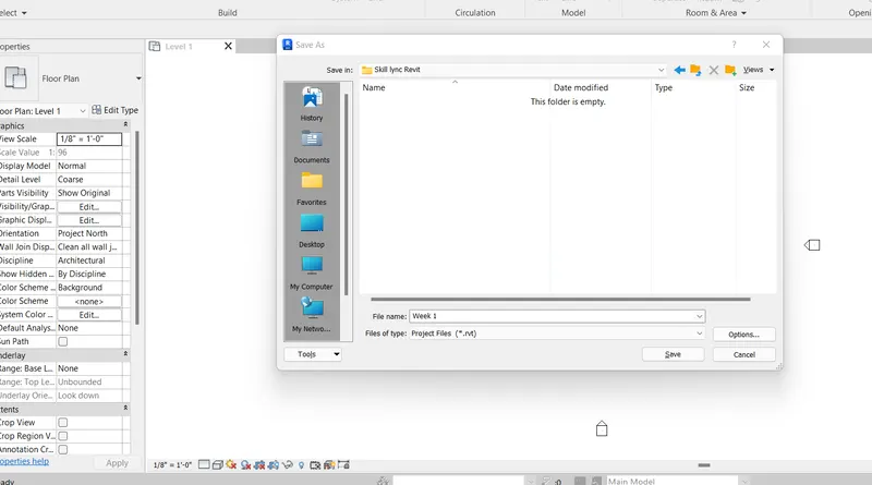
The home page of the Revit software will appear. Go to file menu and select save choose the destination and give name to the file and then save.
Result
Thus, the New Project is created and template is saved
2.Save the new project file. Close and open using icons from file toolbar
Aim
To save the New Project file, Close and open the file from tool bar.
Procedure
Open the Revit software and go to file menu and press save the template will be saved.
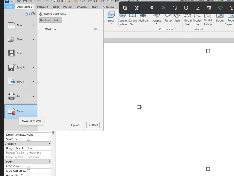
Then go to file menu and go to close and then close the saved file.
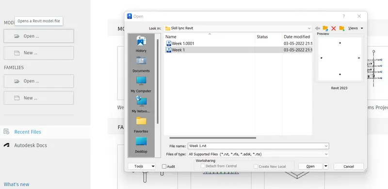
Then in Revit toolbar open, new available press open and then open the saved template again.
Result
Thus, the template is closed and opened by using tool bar.
3. From the architecture/ structure toolbar familiarize with options to draw a wall. Create a rectangular layout of walls of about 40’-0” X 35’-0”
Aim
To draw a rectangular layout of wall of 35’ x 40’
Procedure
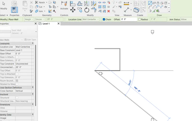
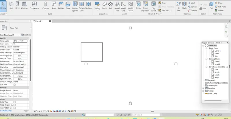
Open Revit Architecture imperial template. Use wall option in that and use line option to draw a wall.
Click on the screen for first point and then more cursour right and give dimension of 40’ and move down and give 35’.
Then in the left provide dimension of 40’ and in up word give dimension of 35’.
The rectangular wall section is created.
Result
Thus, the rectangular wall layout is created.
4.From the Annotate toolbar use the aligned option to add dimensions to the layout
Aim
To give dimensions for the rectangular wall section by using annotate tab.
Procedure
Open the rectangular wall section layout and click on annotate tab.
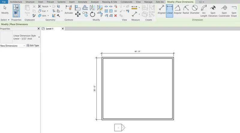
Use linear option and press first end of the wall and then the second end and then drag up and press enter.
Then use aligned potion and select the vertical start of the wall and end point of the wall then drag the mouse side wise and then press enter.
The dimensions of the rectangular wall have been created.
Result
Thus, the Dimensions of the rectangular wall have been provided by using annotate tab.
5.Use the properties browser to switch to different wall types
Aim
To create different wall type by using property browser.
Procedure
Go to Revit software which we have saved previously.
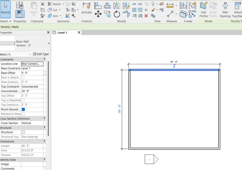
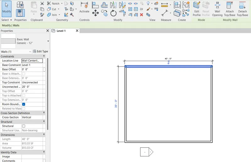
Select any of the wall, in property browser it will show the type of the wall as Generic 8”.
Press the down arrow in the property browser different wall types will appear in that. Use any of the property i.e., Generic 12”.
The wall type will be changed to Generic 12” for particular wall
Result
Thus, the wall type has been created by using property browser.
6.Create a 3D view from the view toolbar and save the view with the appropriate name
Aim
To create the 3D view and to save the view.
Procedure
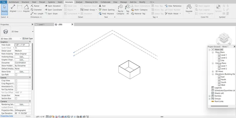
Got o Revit saved project. In the top right there is a 3D option drag it and select Default 3D view.
The 3D view of the rectangular wall has been created.
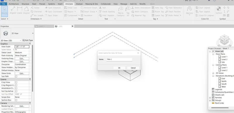
Select the view cube to change the view and if need to save the current view Right click on the view cube and save by providing name to that particular view.
If want to change the view click on the view cube in different location the view will be changed.
Right click on the view cube to save the view.
Result
Thus, the 3D view of the project is created and saved.
7.Navigate through the 3D model using the view cube. Orbit/pan through the model layout created
Aim
To Navigate through 3D model using view cube, Orbit/ pan through the model created.
Procedure
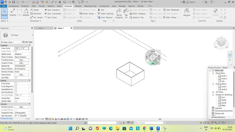
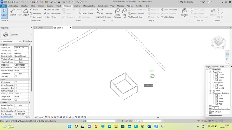
In Revit right side navigation tool bar will be available click on it.
There are more options in it use orbit see the overall 3D view of the layout.
Press pan to move the 3D layout
Result
Thus, orbit and pan tools are used to see the 3D view of the Layout
8.Use the visibility settings option below to switch model to shaded, realistic, hidden lines options
Aim
To use the visibility settings for switching the model to shaded, realistic and hidden lines option.
Procedure
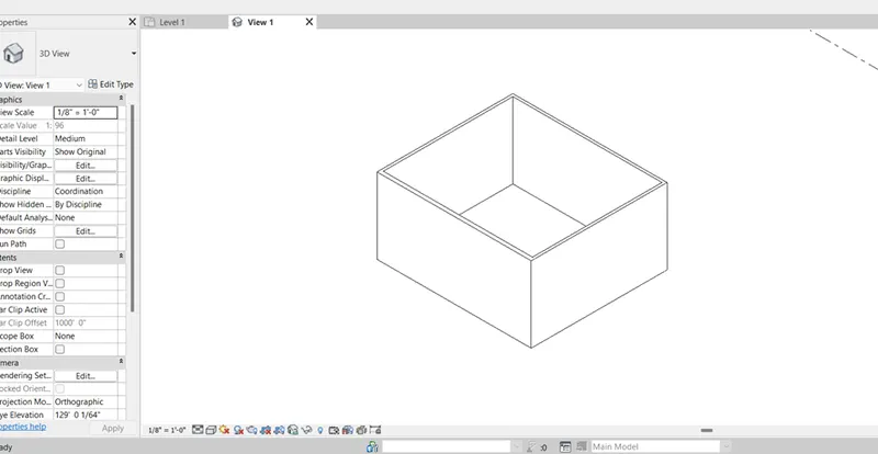
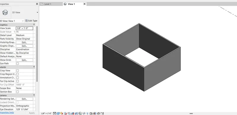
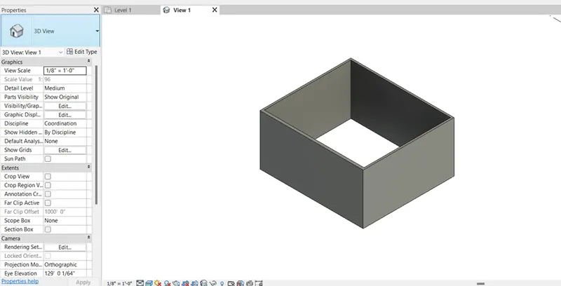
Open the created 3D model. In the bottom tool bar, there is a visibility tool. In that we have shaded, realistic and hidden option we can switch any of the option by using this tool.
Result
Thus, the hidden lines, shaded and realistic views are made and photos attached.
9.Turn the sun path on and off to view shadings in the layout created
Aim
To create the sun path on and off to view the shading in the layout.
Procedure
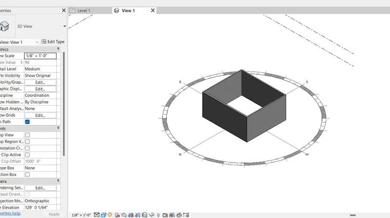
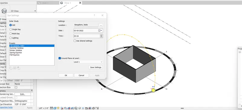
Open the 3D layout of rectangle. In bottom tool bar sun path icon is available.
We can on and off sun path by using this icon.
One sun path is on the path of sun is created and the position of sun also give according to the time.
If we not required sun path go to that icon and turn it off.
Result
Thus, sun path is created to view the shading in the layout.
10.Use the Manage toolbar to enter project settings, project name, and project issue date (choose according to your convenience).
Aim
To use manage toolbar to enter project information.
Procedure.
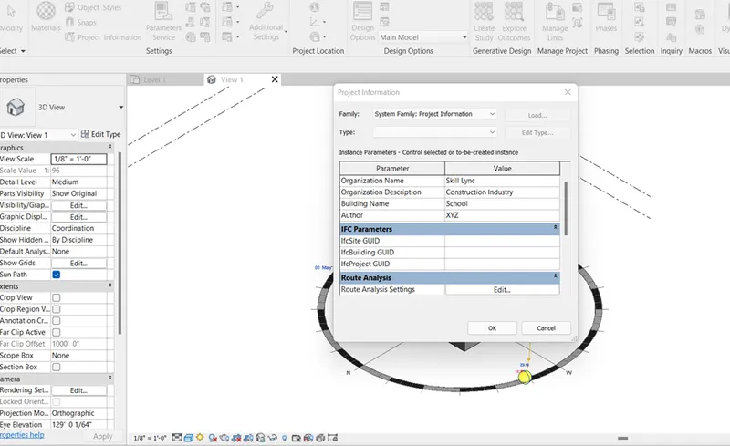
In Revit, use manage tool bar to edit the project information.
Click manage tool bar in the tools and dialogue box of project information is opened. Edit the details entered in it as per the requirements.
Result
Thus, project information is entered by using manage toolbar.
11. What is the Analyze toolbar used in Revit? How it is beneficial for design and modeling
Analysis Toolbar is available at the top options in Revit software.
Analysis toolbar is used to perform structural analysis of the building.
There are various options in analysis toolbar for structural analysis.
The tools like boundary condition, Loads, Load Combinations etc.
12.What are the links that Revit supports to be linked to the model?
In Revit we Have insert tool in that we can line any sort of file to the current model.
We have Link Revit used to link another Revit file to the particular file.
We can also link IFC File, CAD File, and we can also manage files
13.Why do you need the Collaborate tab in Revit? How it supports modeling and its efficiency
Collaborate tab is used to share the work within one work place.
For example in one Revit sample architect, structural, mechanical, electrical, plumbing can do their work and update it in one work place so that every cone can see the work.
In collaborate More person can work in same project with different location without any disturbance.
In collaborate we can share the work in central model whatever the team draws.