Introduction to REVIT concepts
Aim : Intoduction to revit concepts
Introduction:
Autodesk revit is a tool for architects, structural engineers, mechanical engineers, designers and contractors and more. we can model the architectural and structural components for in 3D for for building design, create 2D floor plans and blueprints, model internal components in 3D, annotate design for planning purposes and much more. tje tools and features that make up revit architecture are specially designed to support building informatio model (BIM) workflows.
Project template: project templates provides initial setting to stream line projectsetp and implement the standard standard.
Link multiple projects: Models can be linked together either to indicate the relative location of the building on a campus or to simply coordinates the efforts across the didciplines ( architectural, structural etc).
Work in a team: setting up work sharing post initial design phase can allow multiple team members to work simulataneously. Different desciplane of engineers such as architects, structural engineers, mechanical engineers and electrical engineers, plumbing are working on the same project independently so by using the collabrate tab all members are work simulataneously for the proogressive of the work.
1. From the file menu create a new project (structural/architectural/construction template) and name the project appropriately.
Procedure:
- Open the Revit software.
- From the model select the New option.
- Select the template as a Architectural template and select the OK.
- Click on the file menu select the save option and give the name as project 1 and click on the save.
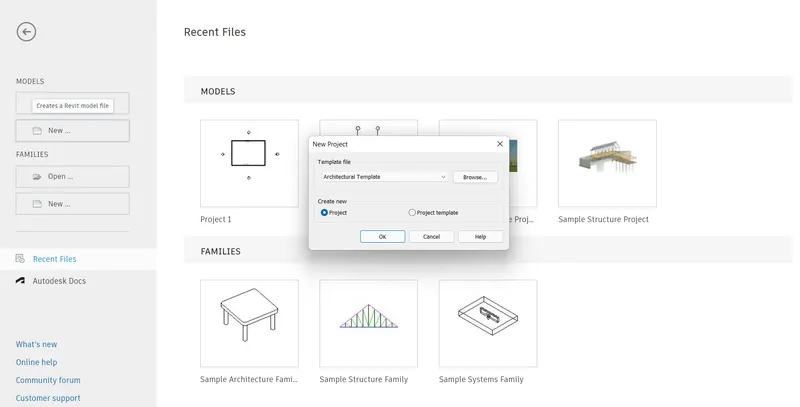
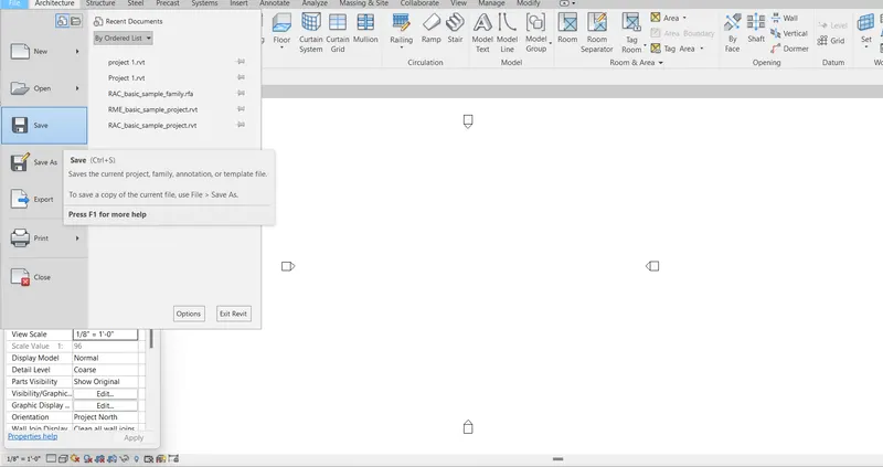
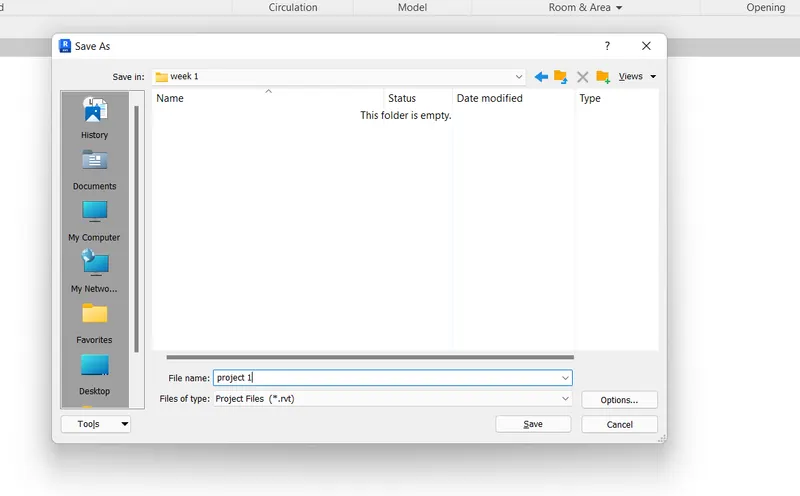
Result:
Created the new project from the menu bar and save the project with a name project1.rvt
2. Save the new project file. close and open using icons from the file toolbar.
Procedure:
- Open the new architectural template sheet.
- From the file menu select the save option and give the file name and save the object.
- Select the file menu
- Click on the close option.
- last drawn project will seen in the recent files from that we can select the project andd open.
- Other wise from the model select open option select the file that saved alredy or from the file menu tab select the open option we can open the already created revit project sheet.
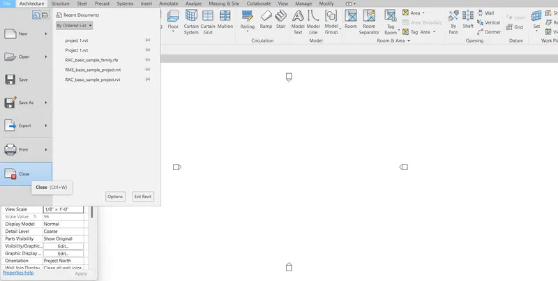
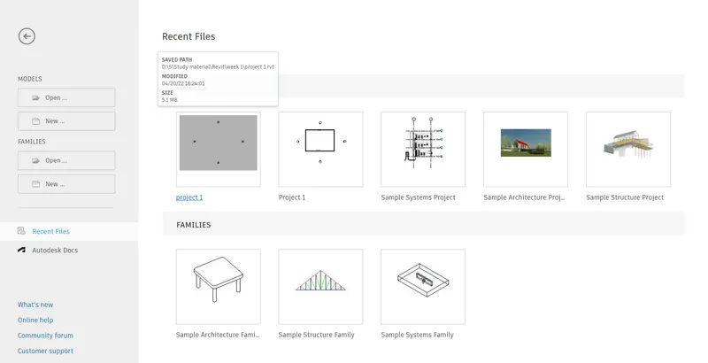
Result:
from the file menu bar the project was saved and closed and opened.
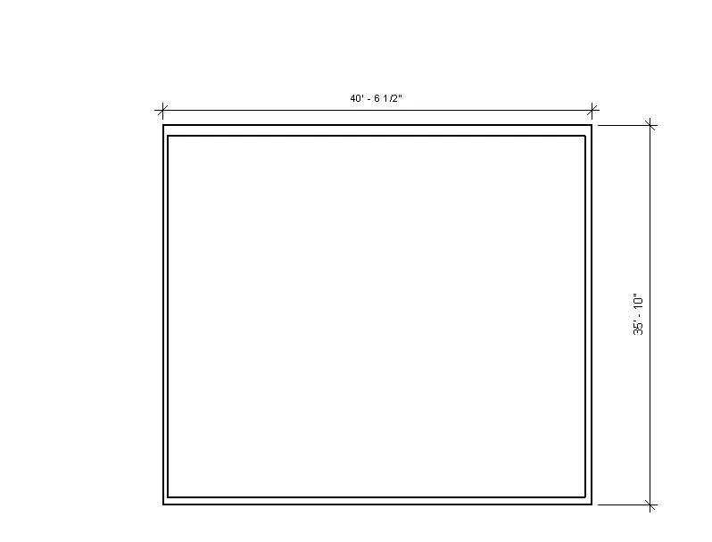
3. From the architectural/structural toolbar familarize with the options to draw a wall. create the rectangular layout of walls of about 40' X 35'.
Procedure:
- open the file that already saved as a project 1.
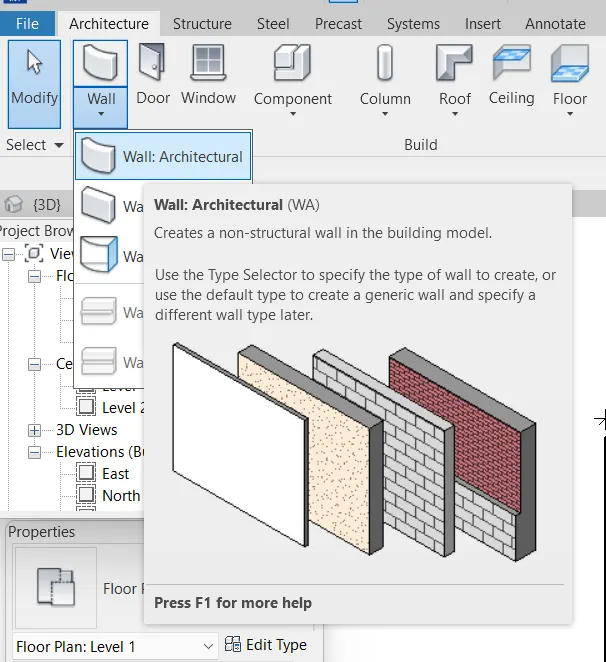
- From the tab select the architecture, in that select the wall
- Give the starting point of the wall and give the horizontal length as a 40' and vertical length as a 35'
- Move the cursor till vertical dotted line appears and join the first point.
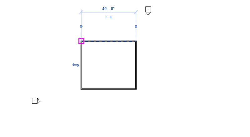
Result:
4. From the annotate toolbar use aligned option to add dimensions to the layout.
Procedure:
- We have already drawn the layout.
- From the tab select the annotate
- select the aligned option select two points that requires the dimensions.
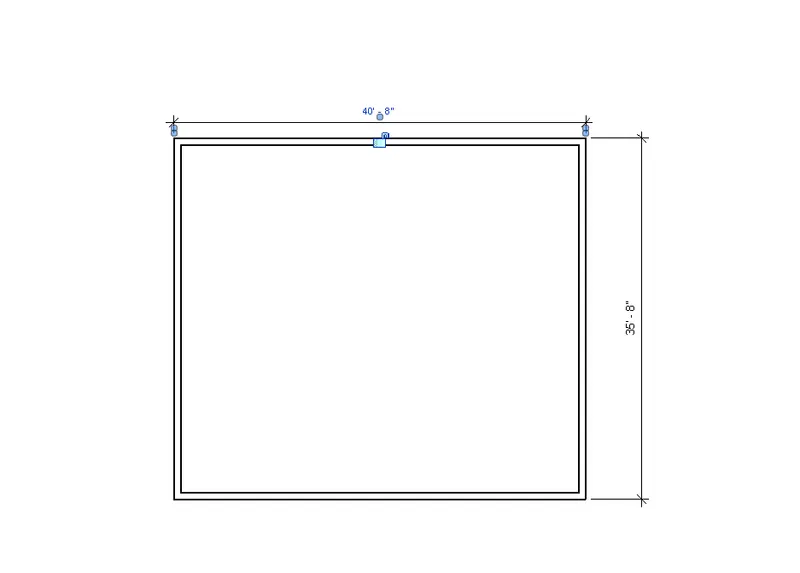
Result:
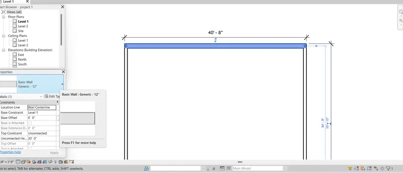
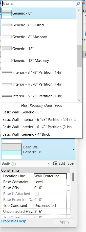
5. Use the properties browser to switch to different wall types.
Procedure:
- Select the wall that need to change the thickness.
- from the project properties click on the wall type and select the different walls.
- the top wall is changes to generic 12"
- The left wall is changes to Interior 5" partitiion
6. Create the 3D view from the view tool bar and save the name with approprite name
Procedure:
- From the top menu bar select the default 3D view or we can select from the view tab select the 3D view.
- from the view cube select the required view.
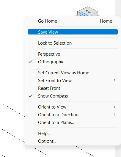
- Right click by keeping the cursor on the view cube select the save view and give the name as required.
- saved view will appear on the project browser on 3D views with the saved name
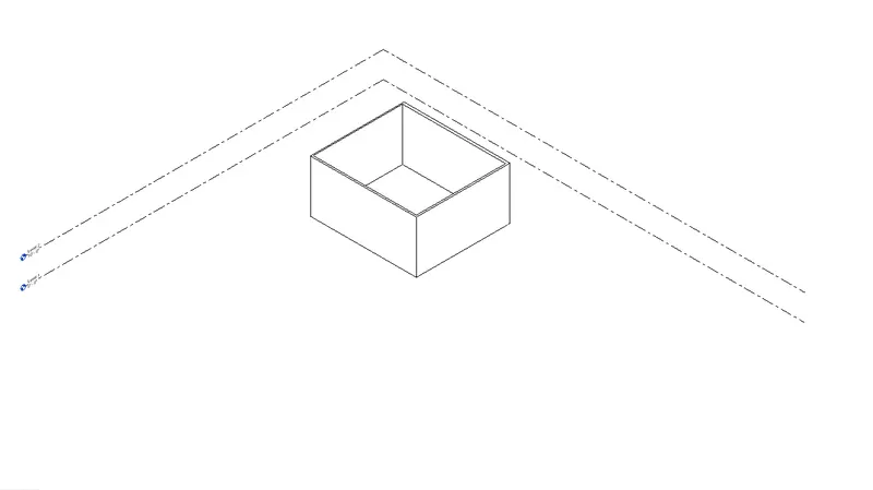
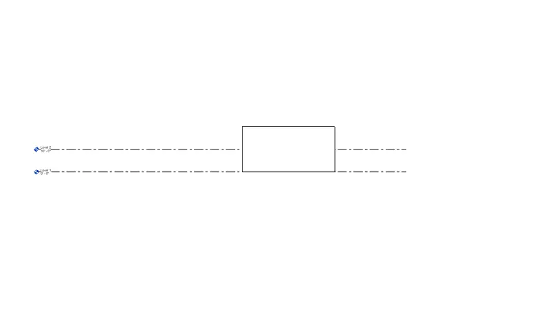
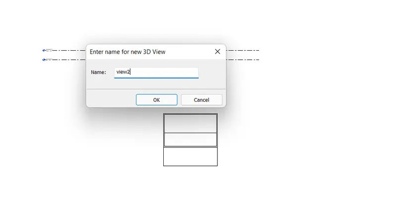
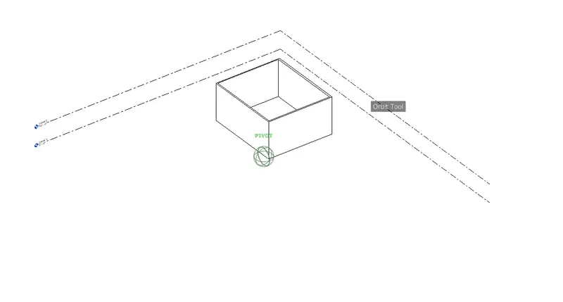
7. Navigate through the 3D model using the view cube . orbit/pan through the model layout created.
Procedure:
- From the view tab select the user interface
- Mark the navigation bar and the navigation bar is appears on the right side.
- Select the navigation wheel.
- Select the orbit and move at the required view.
- we can use the pan option that prestnt on the navigation wheel.
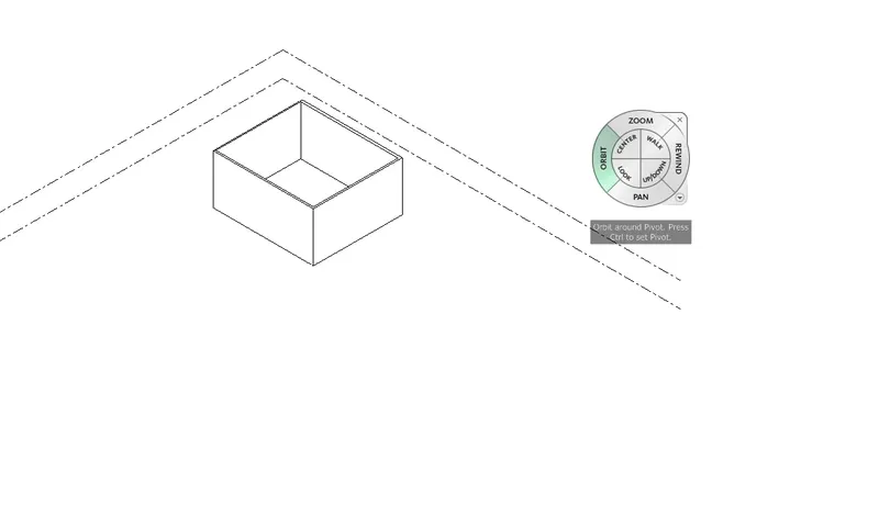
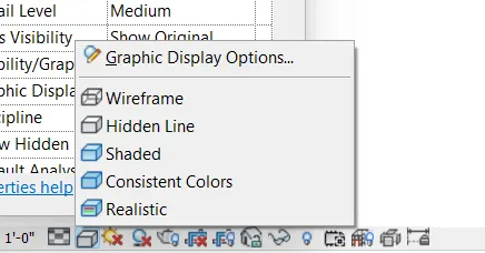
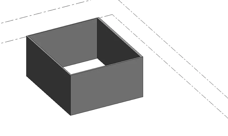
8. use the visibility setting option below to switch the model to shaded, realistic, hidden lines options.
Procedure:
- From the bottom menu bar click on the visual style.
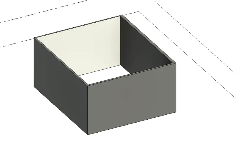
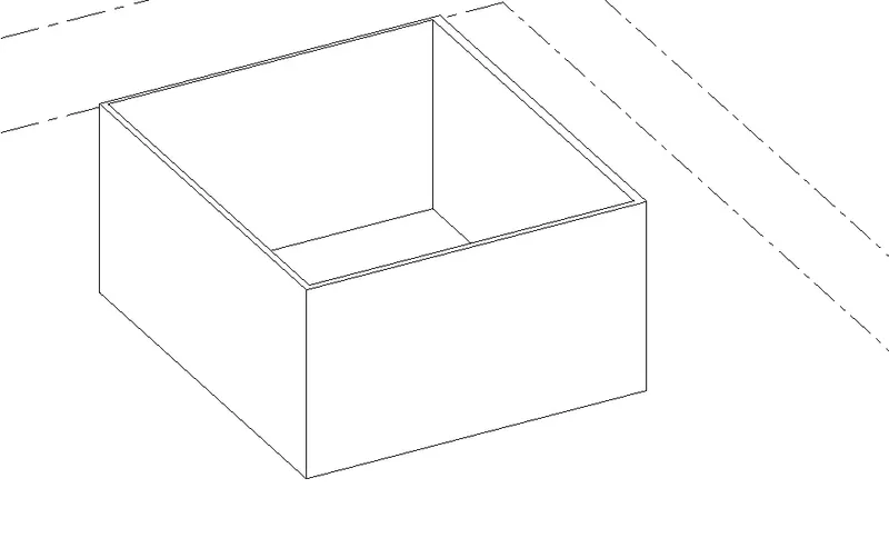
- Select the required visual style such as hidden, shaded and realistic.
Shaded
Hidden Line
Realastic
9. Turn the sun path on and off to view the shadings in the layout created.
Procedure:
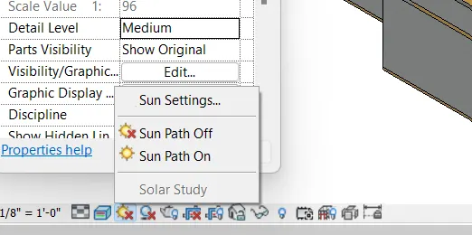
- From the bootom menu bar click on the sun path
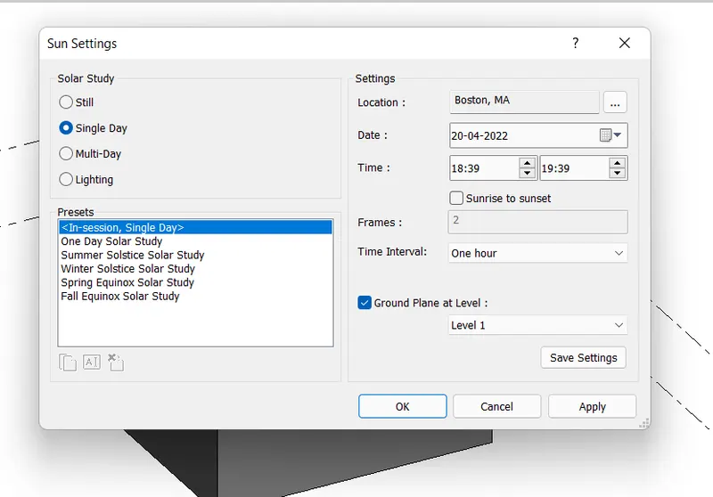
- select the sun setting and give the change the setting
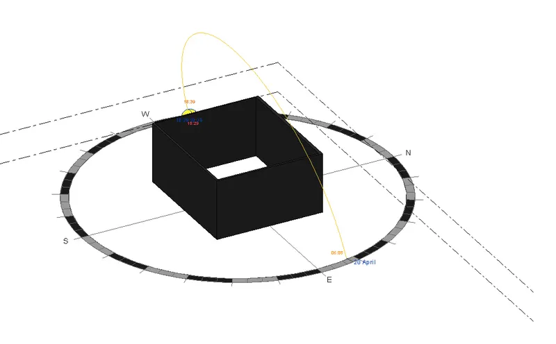
- Click on the sun path on the below images appear.
- Click on the sun path off.
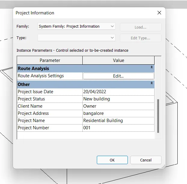
10. Use the manage toolbar to enter project setting, project name, and project issue date ( choose according to your convienece )
Procedure:
- from the manage tab select the project infirmation the below dialogue box will appear.
- Give the necessity parameter such as organisation name, author, building name etc.
- also give the project issue date, project address, client name, project name and project number.
11. what is analyse yoolbar used in the revit? How it is beneficial for design and modelling
- Analyze tab in the revit helps to perform the structural analysis of the building.
- It helps to add the boundary conditions to the model such as point, line and area to the model.
- We can apply point load, line load, and area load to the model to evaluvate the performance of the building.
- By using the load combination we combine the load for perform the analytical model.
- It helps in the energy optimization and energy analysis of the building.
- It creates the energy model from the features thaat given to the model based on the conceptual masses.
- It helps uin heating and cooling analysis based on the existing building model.
12. What are the links that revit support to be linked to the model
The links the revit supports are
- Link Revit: It helps to link the another revit model to the current model.
- Link cad: linking the 2D cad file to the revit
- Link IFC: link the IFC files to the revit.
- Manage link: It provides options for managing the links to building models, cad files, DWF markup files, and point clouds.
- Link Topography: Link the existing topography to the current revit model.
13. Why do you need the Collaborate tab in the revit? how it supports modelling and its efficiency.
- By using the collabrate tab team members work simultaneously.
- Different desciplane of engineers such as architects, structural engineers, mechanical engineers and electrical engineers, plumbing are working on the same project independently so by using the collabrate tab all members are work simulataneously for the proogressive of the work.
- Collabrate enables the users to create the central file or cloud file that can be used by others simulataneously.