Introduction to REVIT concepts
1) AIM & INTRODUCTION: To create a new project and naming the project.
PROCEDURE:
- Open Revit software by double clicking the software.
- From the Revit software click on New and browse the appropriate template (selected the Imperial- Architectural Template). Create new Project and click OK.
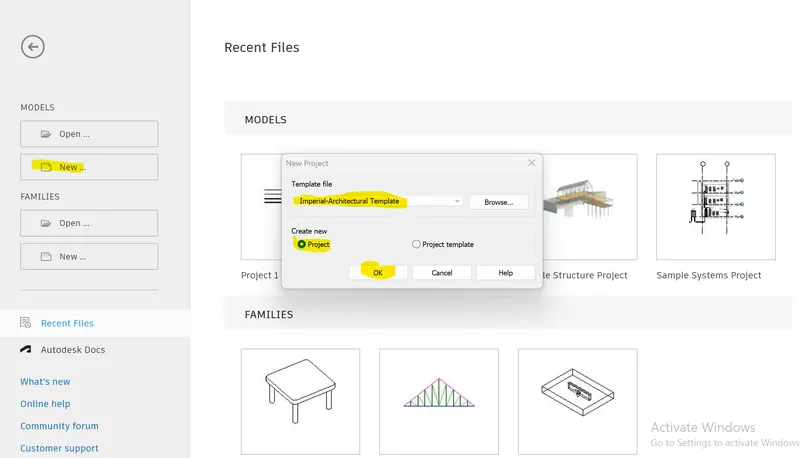
- Revit screen will appear after awhile.
- From File button, select Save option.
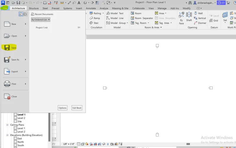
- Choose the destination folder to save and rename the file accordingly and click on save button
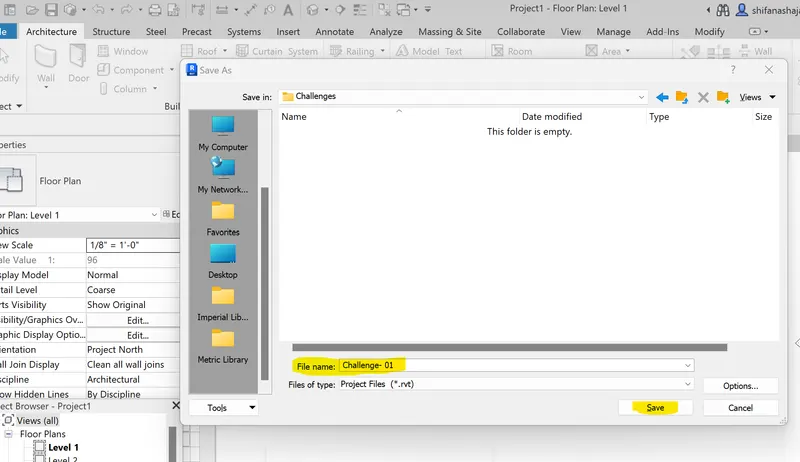
RESULT: By saving the file, the project name is renamed as Challenge -01.
2) AIM & INTRODUCTION: Save the file. Then open and close the project file using File menu.
PROCEDURE:
- Open Revit software.
- Click on File menu and save the file using the Save menu (already saved the file for above Question).
- Again click on File menu and select Close option. Now the Project file has been closed.
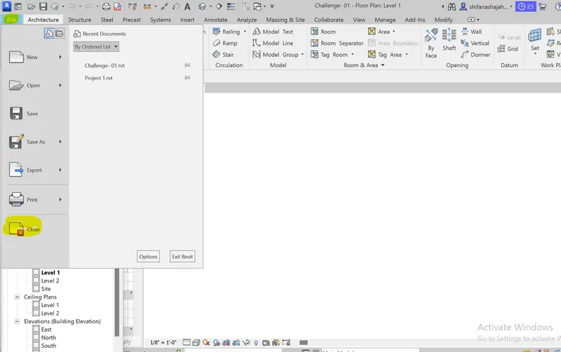
- Then recent files are appeared on the screen, double click the project file from the screen as we saved before.
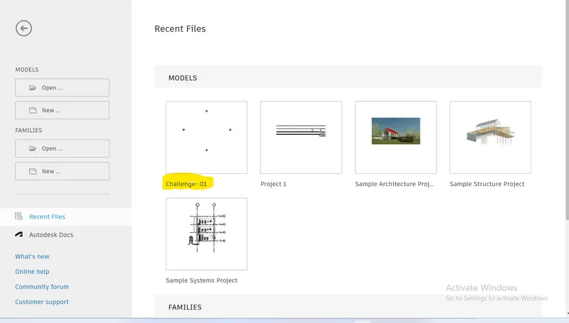
- Project file is appeared.
RESULT: From the file menu we can close the saved file and reopen the file from the recent files.
3) AIM & INTRODUCTION: From Architectural / structural toolbar draw a rectangular layout of wall.
PROCEDURE:
- Architectural Template and click on wall option.
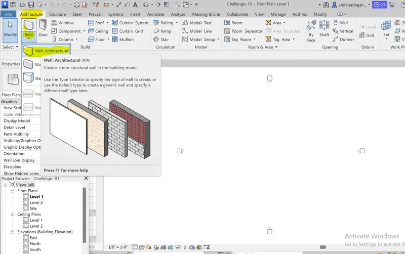
- In the draw tab several options are available to draw a wall. Select Line option to draw appropriate wall.
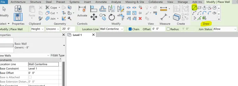
- With Line option, on drawing area drag horizontally then enter 40" and press enter. Then vertically enter as 35" and press enter. Similarly draw other two sides of the rectangle and press enter
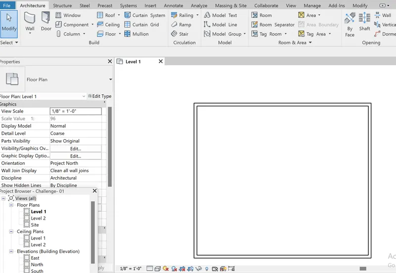
RESULT: From the architecture / structural template wall is drawn with appropriate measures.
4) AIM & INTRODUCTION: From Annotate toolbar add dimensions to the wall.
PROCEDURE:
- Click on Annotate toolbar, there are Aligned, Linear and Angular tools for dimensioning.
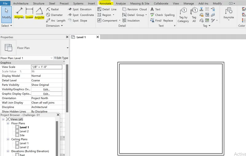
- Select the linear tool for horizontal dimensioning. Click on one corner of the horizontal wall and drag to the other corner and carefully, then move to the particular height above the wall and press enter
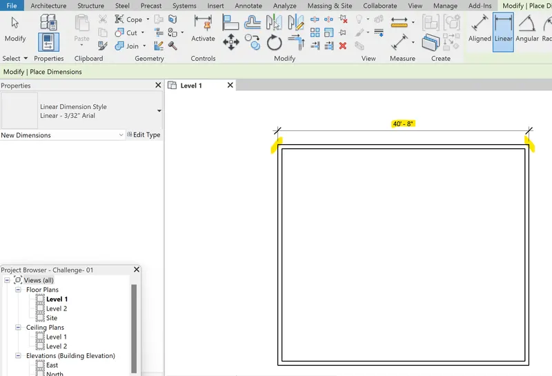
- Similarly select the Aligned tool for vertical dimentioning from one end to another.
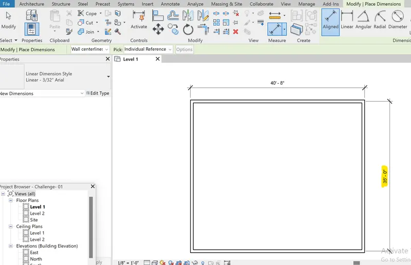
RESULT: Using Annotate toolbar gave the dimensions for the wall by linear and aligned tool.
5) AIM & INTRODUCTION: From property browser need to switch different wall types.
PROCEDURE:
- In the left side of the panel we can see the property broswer with various properties showing on it.
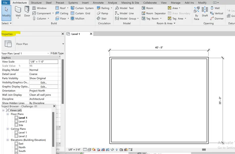
- Click any wall we have drawn, then in properties it will show the type and thickness of the wall. Here the wall is Generic and 8" thickness.
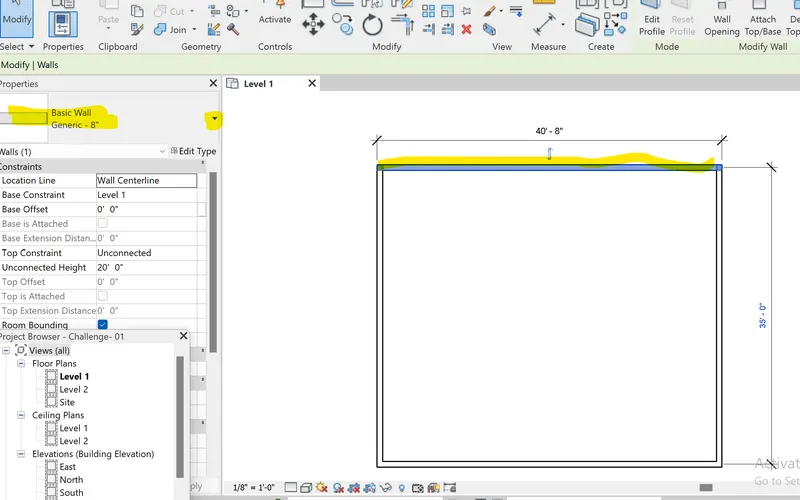
- We can drop down the browser with different types and different thickness. we can select the Generic type and 12" thickness.
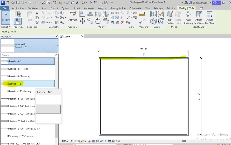
- So the wall thickness has been changed to 12" thickness as shown below.
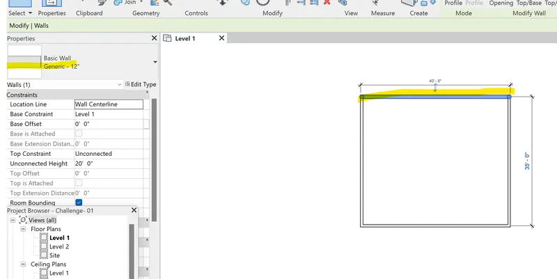
- Similarly we can change the other wall thickness also.
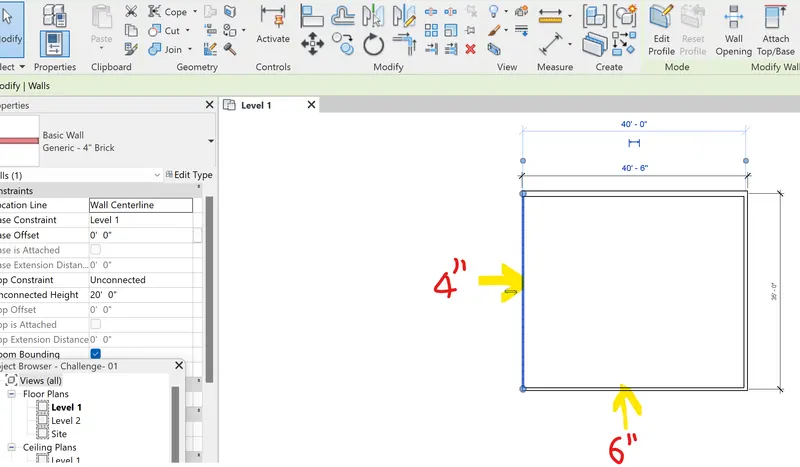
RESULT: Using property browser we can change the different wall type like generic, concrete, brick works and so on similarly thickness can also change as 4", 6", 8", 12".
6) AIM & INTRODUCTION: Need to create a 3D view and save with an appropriate name.
PROCEDURE:
- To switch the floor plan to 3D view click on view option and select 3D view as shown. Or we can select the default 3D view on top.
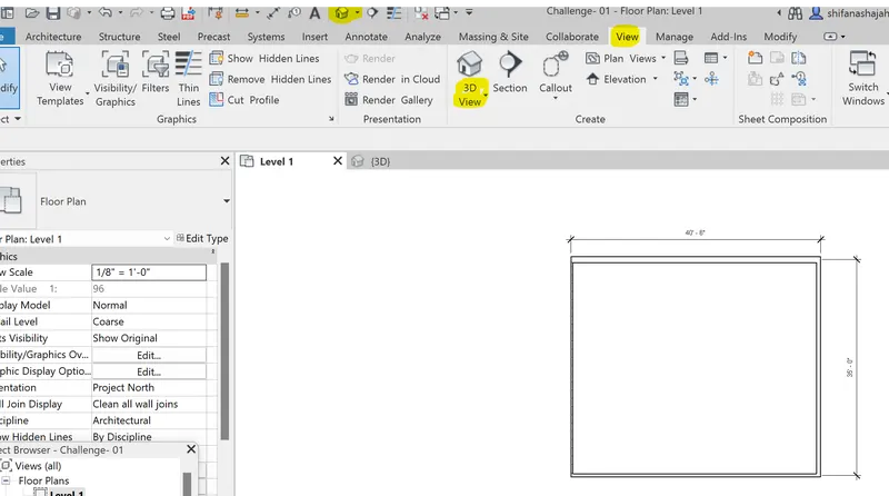
- Click on 3D view so we automatically directed to the 3D view. In right corner there is a view cube. Click on any corner of the view cube to see the desired side 3D view
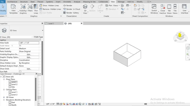
- Right click on the corner of the view cube which we selected to save the view. Rename the view (given as 3D view 1). Then press Ok. Similarly we can save the other 3D views.
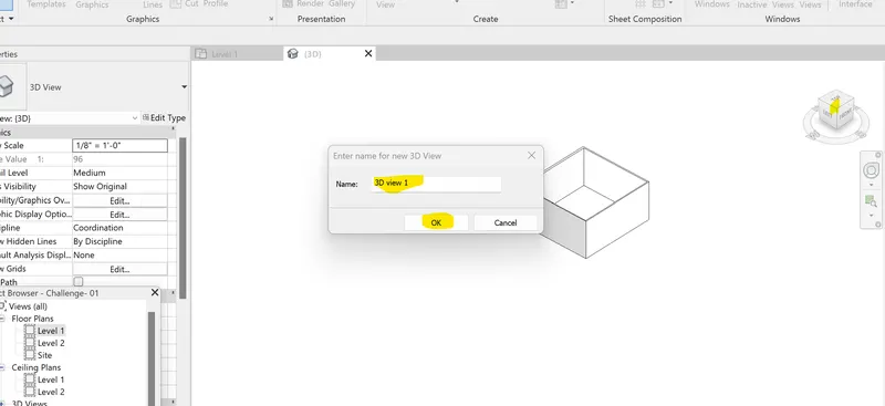
RESULT: From the 3D view we can place different 3D views and can save each 3D views.
7) AIM & INTRODUCTION: Need to navigate through the 3D model and orbit / pan through the model layout.
PROCEDURE:
- In the 3D view right side there is full navigation wheel having Orbit, Zoom, Pan and Rewind.
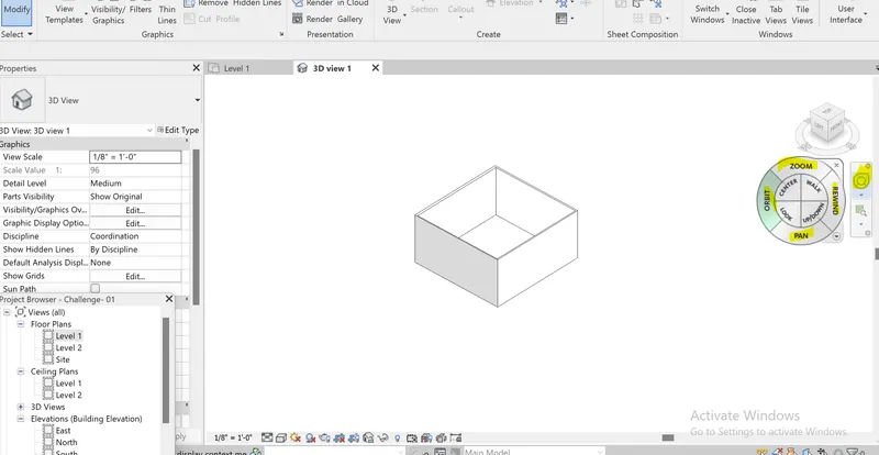
- For orbiting to 360 degree, the 3D view click and drag into the 3D model.
- Similarly for Pan, click on Pan tool and drag for pan the 3D model.
RESULT: Using navigation wheel we can Orbit/ pan or zoom the 3D model to the desired view.
8) AIM & INTRODUCTION: Using visibility settings need to switch the model into shaded, realistic, hidden lines option.
PROCEDURE:
- From the bottom toolbar there is visual style having various options like wireframe, hidden lines, shaded, realistic.
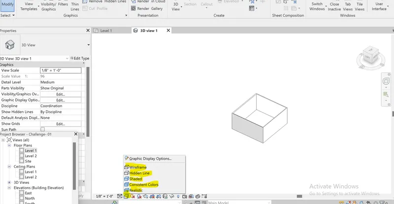
- click on the shaded option to view the 3d visual style as shaded
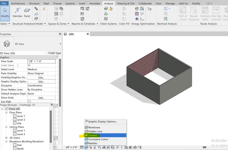
- Similarly we can make the model to realistic, wireframe, hidden lines.
RESULT: Using visual style toolbar we can view the 3D model in different styles as shaded, wireframe model, realistic for better visualisation.
9) AIM & INTRODUCTION: Need to turn the sun path on and off to view shadings in the layout created.
PROCEDURE:
- There is a dedicated option for sunpath on and off in the bottom toolbar as shown below.
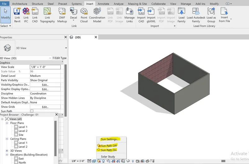
- By selecting the sunpath On there is a dialogue box appeared, select the continue with current settings. Then we can see the sun path in the model
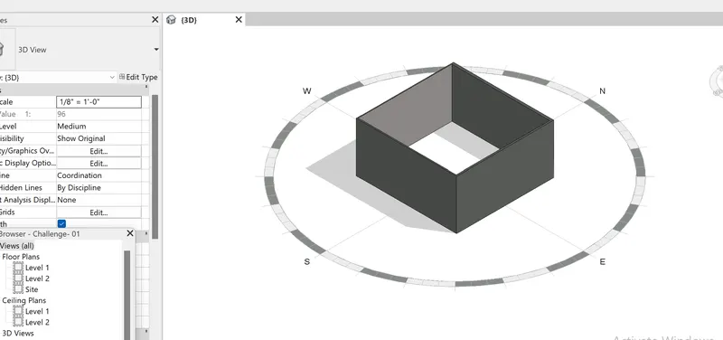
- When sunpath is Off it will disappear.
- When we select the Sun settings we can provide the solar study, precasts, time, location as our preference. Then press OK.
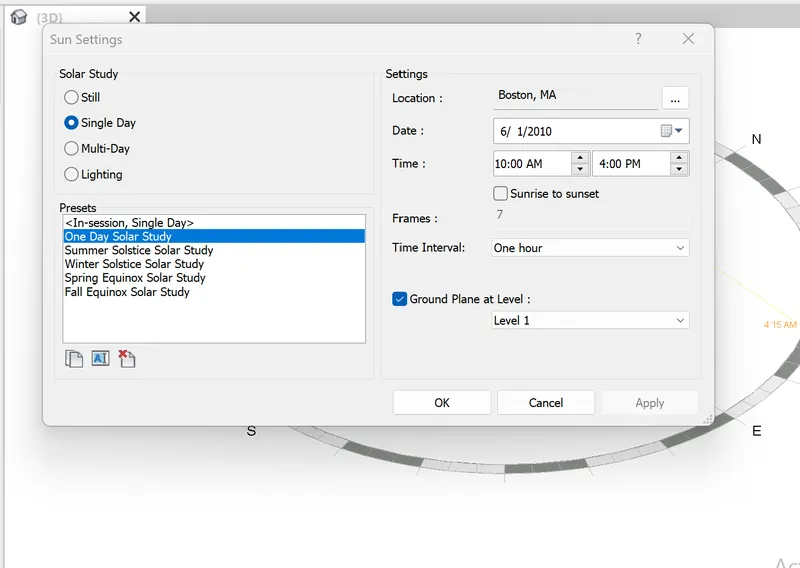
- Thus sunpath will appear in the given setting mode
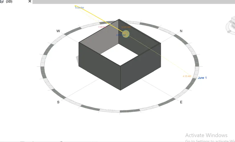
RESULT: We can On and Off the sunpath from the sunpath menu. Also we can give the location of project and time thus sunpath will come accordingly.
10)AIM & INTRODUCTION: By using manage toolbar need to enter the details such as project name, project issue date and so on.
PROCEDURE:
- Click on manage toolbar and select project information tool.
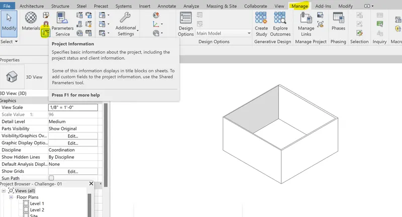
- In the project information provide the details as shown below.
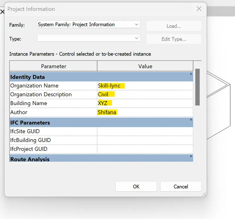
- Also provide the project issue date and provide full address of the project as below and press OK.
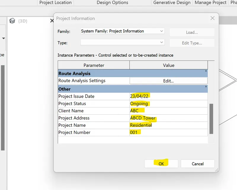
RESULT: From the manage toolbar we can give all the project information.
11) AIM : To know about analyze toolbar on revit.
INTRODUCTION:
- Analyze toolbar can be used to analyze the structural analysis of the building.
- There are various options to analyze the process.
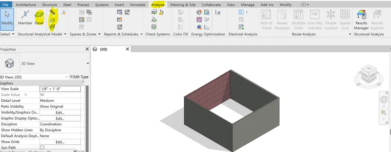
- Analytical member- Places an analytical member to the project.
- Analytical panel- Opens a sketch mode where we can draw the contour of the analytical panel to place in the project.
- Analytical link- Creates an analytical element that connects two seperate analytical nodes.
- Boundary condition- Defines point, line and area boundary conditions in an analytical model.
- Loads- Applies point, line and area loads to a model.
12) AIM: Links that Revit supports to be linked to the models:
INTRODUCTION: The links supports to the model are:
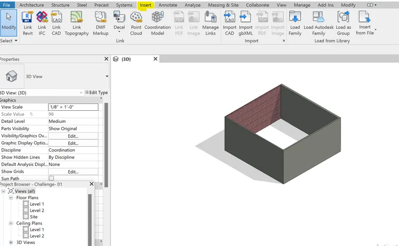
- Link Revit: Links another Revit model to the current model.
- Link IFC: Links an IFC file to the current project to reference its information for additional design works.
- Link CAD: Links a CAD file to the current Revit project.
- Link Topography: Links existing topography to the current Revit project.
- DWF markup: Links marked-up DWF files into a Revit projects so you can see the markups on corresponding sheets.
- Decal: Places an image of surfaces of a building model for rendering.
- Point cloud: Links a point cloud file into the revit project.
- Coordination model: Links a NWD or NWC file to provide context for the revit model.
- Manage links: Provides options for managing links to building models, CAD files, DWF markup files and point clouds.
13) AIM: Need of Collaborate tab in Revit and its efficiency.
Revit provides several different ways to collaborate with team members who are also using the software.
- We can link multiple Revit models together, allowing team members to work in context.
- Through worksharing, users on the same local area network (LAN) can work together in the same Revit model.
- When collaboration needs to occur among users who are not in the same geographic location, use Revit Server or Revit Cloud Worksharing.
- Revit Server connects offices who share a network but are not in the same geographic location.
- Revit Cloud Worksharing is a cloud-based service that allows any Revit users inside or outside a network to collaborate on a Revit model.