3D Creation of Celing, Roof, Architectural plan, Structural plan, Sectional view, Elevation view and Camera specific view for a house plan using REVIT
1)Based on the project saved from Week 3, proceed from the First Floor Level. Model a Ceiling from the architecture tab above the walls at the first-floor level.
AIM:
To model a Ceiling from the architecture tab above the walls at the first-floor level.
INTRODUCTION:
Just like Floors and Roofs, Revit Ceilings consist of 3D model geometry and non-graphical parametric data. They are created by use of the dedicated Ceiling tool.
-
Automatic Ceiling: This will make Revit detect where there are bounding Walls that enclose potential ceiling spaces. In short- Revit is going to try and guess from your model where ceilings should be created.
-
Sketch Ceiling: This allows you to sketch where you want your Ceiling elements created.
PROCEDURE:
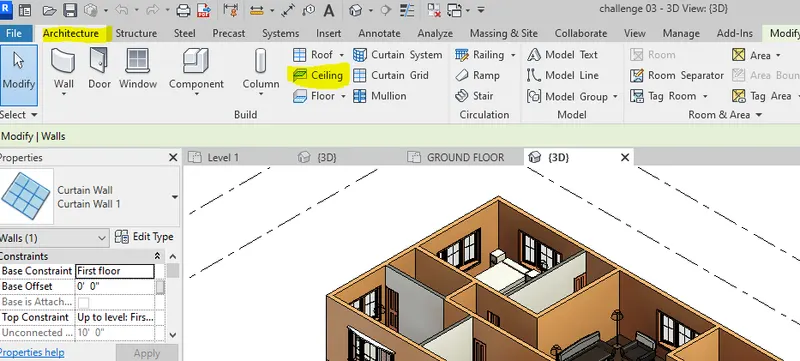
- First we open the Week 3 project from revit sofware , and select the ceiling option from the architecture toolbar.
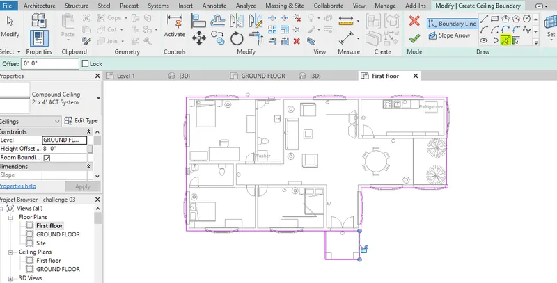
- Select the boundaries of the first floor by pickline option as shown below.
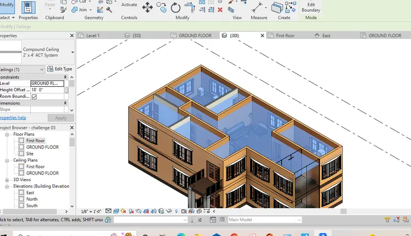
- After finishing the boundaries the ceiling is visible in the 3D view as shown.
RESULT:
The ceiling has been created in the first floor level fromthe architectural tab above the walls.
2) Model a roof above the ceiling by selecting the footprints of the ceiling. Using the adjustment toolbars appearing on-screen adjust the roof slope to 10 degrees.
AIM:
Need to model a roof above the ceiling by selecting footprints of the ceiling.
INTRODUCTION:
Roofs have been constructed in a wide variety of forms flat, pitched, vaulted, dimed, or in combinations as dictated by technical, economical or aesthetic considerations. By applying the Defines Slope property to lines of a roof boundary, you can create different roof types, including flat roofs, gable roofs, and hip roofs. We can model quite a few roofs simply by using Revit’s ‘Roof by Footprint’ tool. For more complex roof profile shapes, ‘Roof by Extrusion’ is typically used.
- Display a floor plan view or a reflected ceiling plan view.
- Click Architecture tabBuild panelRoof drop-down
 (Roof by Footprint).
Note: If you try to add a roof on the lowest level, a dialog prompts you to move it to a higher level. If you choose not to move the roof to a different level, Revit notifies you later if the roof is too low.
(Roof by Footprint).
Note: If you try to add a roof on the lowest level, a dialog prompts you to move it to a higher level. If you choose not to move the roof to a different level, Revit notifies you later if the roof is too low. - On the Draw panel, select a sketch or pick tool. To edit roof properties before sketching, use the Properties palette.
Tip: When using Pick Walls, you can specify the overhang before you sketch the roof. On the Options Bar, select Extend to wall core if you want the overhang to be measured from the core of the wall, and then specify a value for Overhang.
- Sketch, or pick, a closed loop for the roof.
- Specify slope defining lines. To change the slope definition of a line, select the line and, on the Properties palette, click Defines Roof Slope. You can then change the slope value.
When a roof line is set to slope defining, this symbol
 appears adjacent to it.
 - Click
 (Finish Edit Mode), and then open a 3D view.
PROCEDURE:
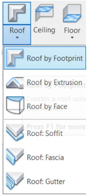
- From the architecture toolbar, select the Roof by Footprint option as shown below.
- Select the pick line option from Footprint,then select the boundaries of the plan and provide the slope as 10 degree in the property browser.
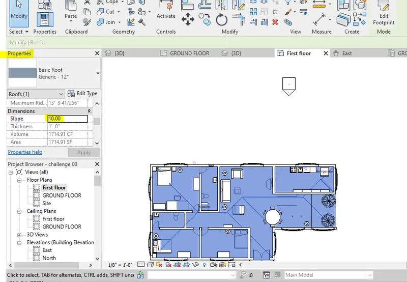
- The roof with 10degree slope has been created in the 3D view.
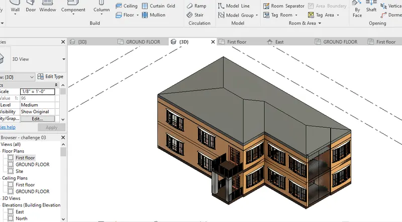
RESULT:
Roof has been created above the ceiling by selecting the footprints of the ceiling with a roofslopeof 10degree.
3) Using the file saved from weeks 2 to 4, create plan views for ground floor level and first-floor level including all the walls, floors, and components. Separate them to
architecture and structural plans
a. Architecture plan must have walls, floors, and all the components placed within the building
b. Structure plan must have details of only walls, floors, and columns
AIM:
Need to create plan views for ground floor level and first-floor level including all the walls, floors, and components. Separate them to
architecture and structural plans.
INTRODUCTION:
Autodesk Revit Architecture is a modelling and detailing tool, that is best suited for architects and modelling purposes. Revit Architecture specific tools can be found on the ‘Architecture’ tab. It is all about the build environment.
Revit Structure is a structure tool that is primarily used by structural engineers. Autodesk narrowly differentiates between Revit, MEP and Structure so as to increase the functioning and work progress. Revit Structure specific tools can be found on the ‘Structure’ tab. They are also about the built environment but includes tools for analysing and graphically presenting loads in the structure.
The floor plan view is the default view in a new architecturalproject.-MOst projects include atleast one project plan.
PROCEDURE:
- From the project browser select the Ground floor from Floor plan.Then select the View tab and go to Plan view tool from Create panel.
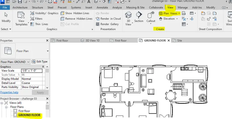
From the drop down menu select the Floor plan. Then Architectural view for the Ground floor is created.( Here I am doing in Architectural plan,so automatically Floor plans are created in Architectural view).
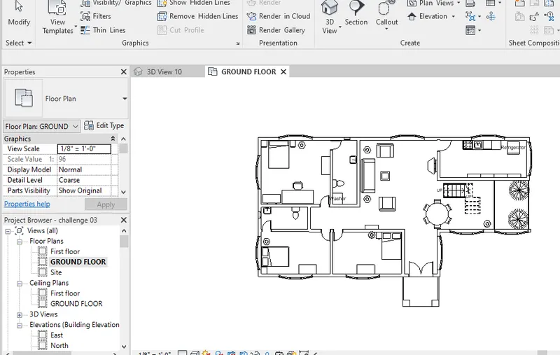
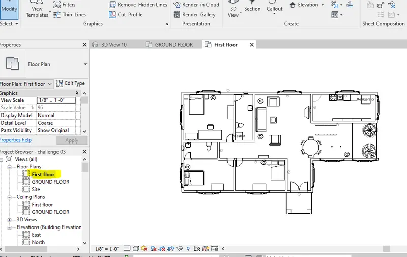
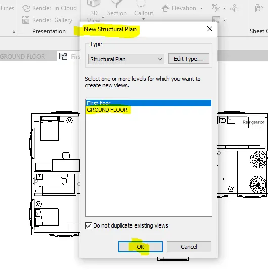
- From the view tab, select the Plan view tool fromthe create panel. Choose Structural plan from the dropdown list.
- Then a dialogue box appears as New structural plan. Select the Ground floor fromthe available list. Click OK.
- Hence the Structural plan for Ground floor is created.
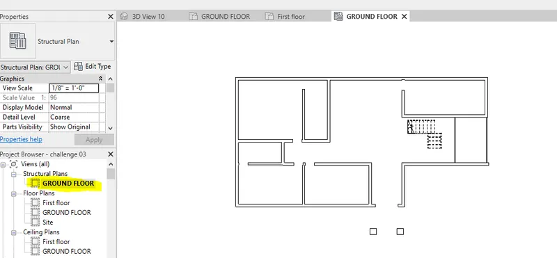
- Similarly,select the view tab and select the Plan view tool from the create panel. Choose Structural plan from the dropdown list.
- Then a dialogue box appears as New structural plan. Select the First floor fromthe available list. Click OK.
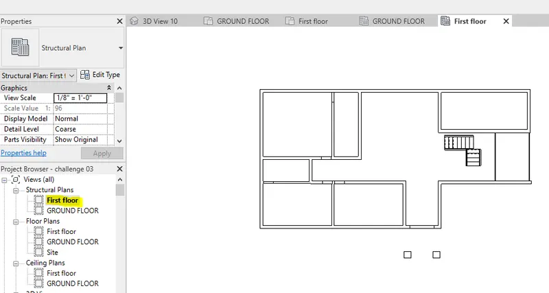
- Hence the Structural plan for First floor is created.
RESULT:
- The plan views for ground floor and first floor has been created for both the architectural and structural plan.
4) Using annotate toolbar add dimensions to all the walls and floors with reference to the longitudinal and transverse grids created in the project file
a. The architecture plan dimensions include details on where the components are placed within the buildings with relation to grids. Overall dimensions are sufficient for architecture plans
b. The Structure plan dimensions must include details on the position of all the walls and interior walls with reference to grids. Locate all the framing components of the building with reference to a fixed point using Structural plans
AIM:
Need to add dimensions to all the walls and floors with reference to the longitudinal and transverse grids created in the project file.
INTRODUCTION:
Quick Dimensions automatically adds dimensions to your selected elements (including those in elevations and sections), creates multiple dimension chains at one go, and joins isolated dimensions into a chain.
- Automatically add dimensions to selected architectural, structural or mechanical elements.
- Create multiple dimension chains in one click.
- Join separate dimensions into a dimension chain.
PROCEDURE:
- First we need to add longitudinal and transverse grid lines to the architectural and structural plan as shown below using grid option.
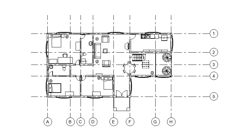
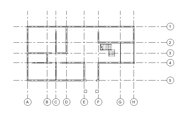
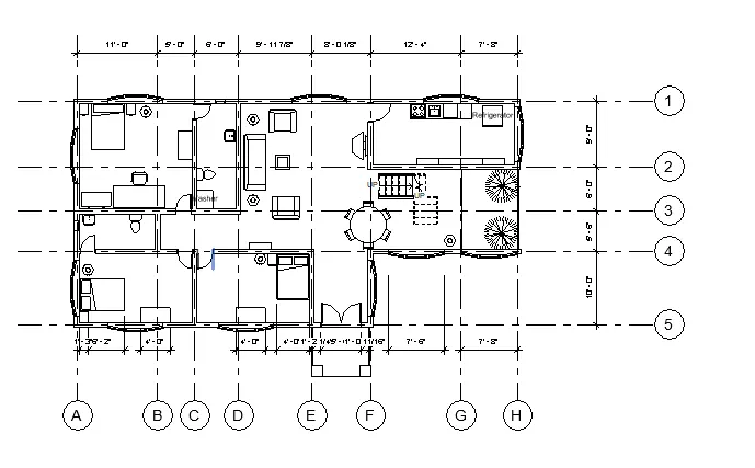
- Add dimensions using annotate tab in the architectural plan include details on where the components are placed within the buildings with relation to grids.
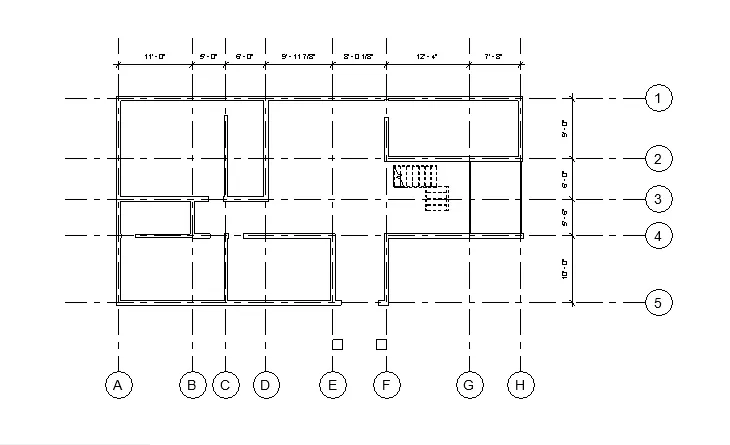
- Add dimensions using annotate tab in the Structural plan dimensions must include details on the position of all the walls and interior walls with reference to grids.
RESULT:
All dimensions are added to the architectural and structural plan with reference to the longitudinal and transverse grids created in the project file.
5) Create a sheet template from the view tab and adjust the parameters on the sheet to add appropriate views
AIM:
Need to create a sheet template from the view tab and adjust the parameters on the sheet to add appropriate views.
INTRODUCTION:
- Create views on a project template before you start building the model to streamline the project documentation process.
- When creating a project template, you can include sheets in the template. Start with a blank project file, and create the standard views and levels that each project should include. Leave the views empty, but assign standard names to them.
- To create a standard set of construction documents, create sheets using the desired title blocks. Add views to the sheets, using the desired viewport templates and view title types. Then save the empty project as a project template.
- When you create a project using this project template, all of the views and sheets are already created and listed in the Project Browser. As you start to draw the building model in the project views, the views on the sheets update automatically. This technique streamlines the project documentation process and maintains organizational standards.
PROCEDURE:
- Click on Sheet option from the view toolbar as shown below.
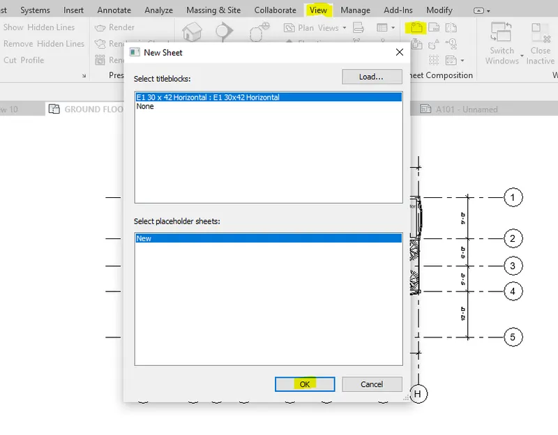
- Then a new tab appears. Select the appropriate sheet template and click OK.
- So we got a new sheet as shown below.
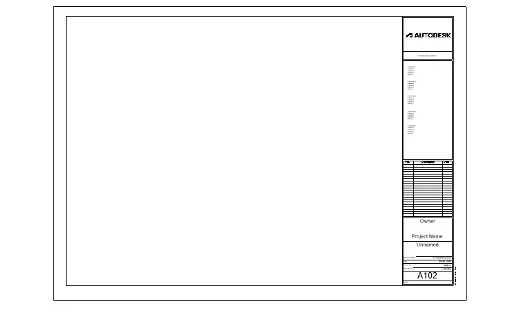
- We can edit the parameters in the sheet and add appropriate view to the sheet.
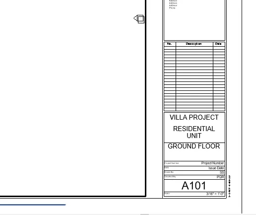
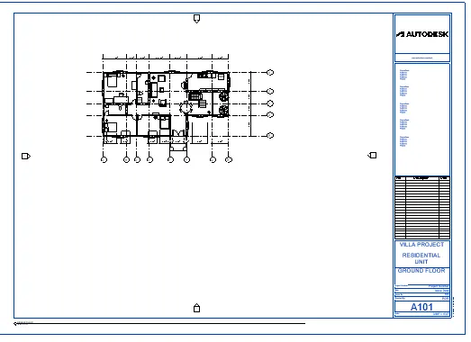
RESULT:
Created a sheet template from the view tab and adjust the parameters on the sheet to add appropriate views.
6) Using the elevation tab create the elevation views, looking at your building from East, North, South, and West
AIM:
Need to create the elevation views, looking at your building from East, North, South, and West using the elevation tab.
INTRODUCTION:
- Elevation views are part of the default template in Revit Architecture. When you create a project with the default template, 4 elevation views are included: north, south, east, and west. It is in elevation views where you sketch level lines. For each level line that you sketch, a corresponding plan view is created
-
You can create additional exterior elevation views and interior elevation views. Interior elevation views depict detailed views of interior walls and show how the features of the wall should be built. Examples of rooms that might be shown in an interior elevation are kitchens and bathrooms.
PROCEDURE:
- Click on elevation option from the view toolbar as shown below.
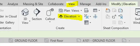
- Choose elevation option fromthe drop down list. Then a bullet icon appears and place thse bullets in 4 directionsas East, North, West and South.
- Go to Project Browser, in the elevation views these views are created. Edit the name as East, North, West and South.
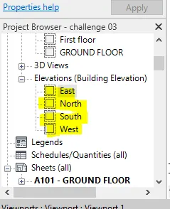
- Click on each elevation view for the realistic appearance.
EAST 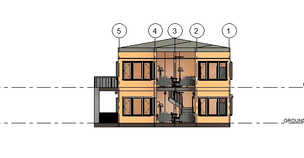
NORTH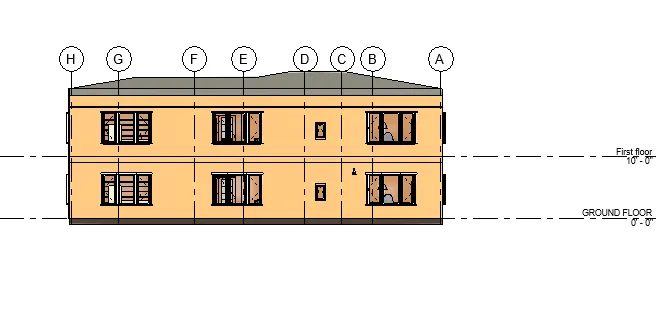
SOUTH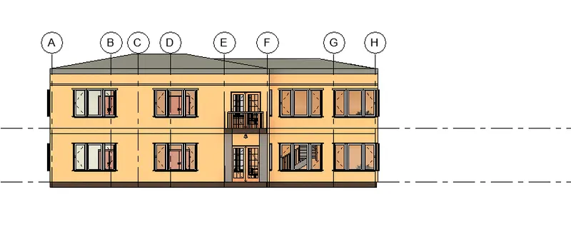
WEST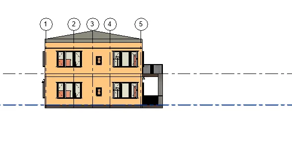
RESULT:
Created the elevation views, looking at your building from East, North, South, and West.
7) Produce section cut through each room either cutting across longitudinally or in a transverse direction
AIM:
To produce section cut through each room either cutting across longitudinally or in a transverse direction
INTRODUCTION:
- A section is a cross-section in a building model that you place by drawing a line. The view associated with this section is known as a section view.
A section cuts through a model so that the interiors of model components along the section line are visible. - There are three default types of sections: building, wall and detail.
Each type of section appears in a separate listing in the Project Browser. -
By simply using the section tool you can select the location, orientation and extents of a section view. Revit will automatically process all objects that are cut through and all objects that may be seen within the view, ensuring nothing is missed.
- You can split sections into segments that are at right angles to the view direction.
You can then use these segments to show parts of a building model located at different distances.
PROCEDURE:
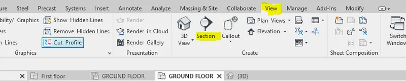
- Click on the section option fromthe view toolbar as shown below.
- After selecting section toolbar place the section on the bedroom toproduce the section views either longitudinally or transversely.
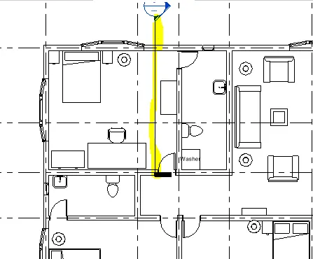
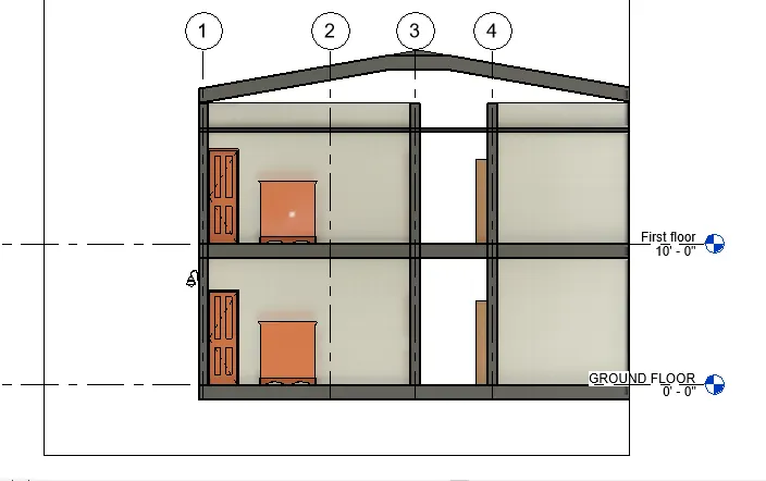
- Here I placed longitudinally on Bedroom 1 for the section view as shown below.
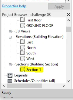
- Then in project browser and go to section views edit the name of the section view we created.
- This is the section view of the Bedroom 1
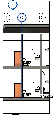
- Similarly take the section view of toilet
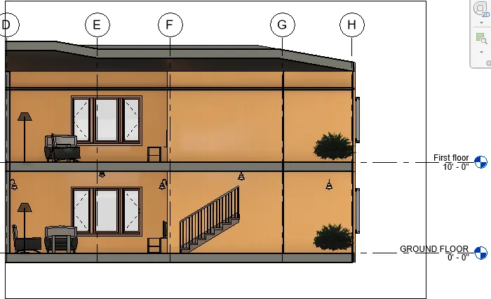
- Section view of Hall
- Section view of Kitchen
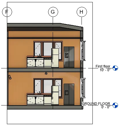
- Section view of Patio
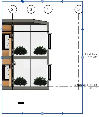
- Section view of 2 bedrooms
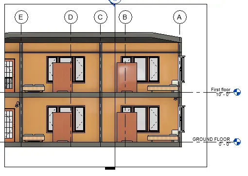
RESULT:
Sectional views are created longitudinally and transversely.
8) Classify the views, Plan Views, Section Views, and Elevation views to either Design or Documentation category using Properties browser
AIM:
Using Property browser classify the views, Plan Views, Section Views, and Elevation views to either Design or Documentation category.
INTRODUCTION:
- Project browser can be organized by creating a new project browser sort group for views /sheets and schedules. Currently, these are the only elements that can be organized and grouped.
- Right clickon the model space and select the project browser option from the dropdown list.
- Then the project browser appears at the left side of the screen.
- Under project browser we can classify the views.
PROCEDURE:
- Using the property browser we can classify the views, plan views, section views, elevation views as follows.
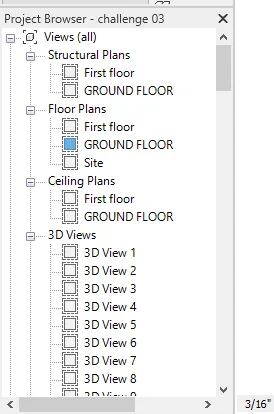
RESULT:
By using property browser classified the views, Plan Views, Section Views, and Elevation views to either Design or Documentation category.
9) Using the sheet template produced create multiple sheets as follows
a. A 101- Ground Floor Architecture Plan
b. A 102- First Floor Architecture Plan
c. A 103- Roof Plan
d. S 101- Ground Floor Structural Plan
e. S 102- First Floor Structural Plan
f. S 103- Roof Framing Plan
g. A-201- North-South Elevations
h. A-202- East-West Elevations
Add additional sheets based on the sections created in your Revit file
AIM:
To create the multiple sheets using the sheet template produced.
INTRODUCTION:
- In the Project Browser, under 3D Views, click the View to Building view title and drag it to the upper right corner of the sheet, and release the mouse button.
An outline of the view displays for easier placement.
- Click to place the view.
PROCEDURE:
- From the Manage Tab , click on project information and edit the project information. Then click OK.
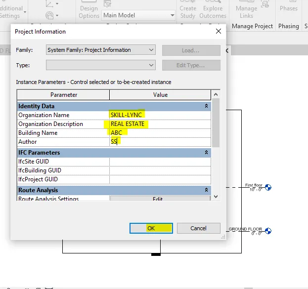
- So the datas are added into the sheet.
- Got to view tab and clickon sheet option. Then new sheet dialogue box appears. Select the sheet and press OK. Then the new sheet appears.
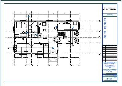
a) From project browser drag the Ground floor Architectural plan into the sheet with a desired scale.
- Then edit the title block as Ground floor Plan and number as A101. Also edit the name on the Project browser sheet view as A101-Ground Floor Plan.
b) Similarly add the first floor plan into the new sheet.
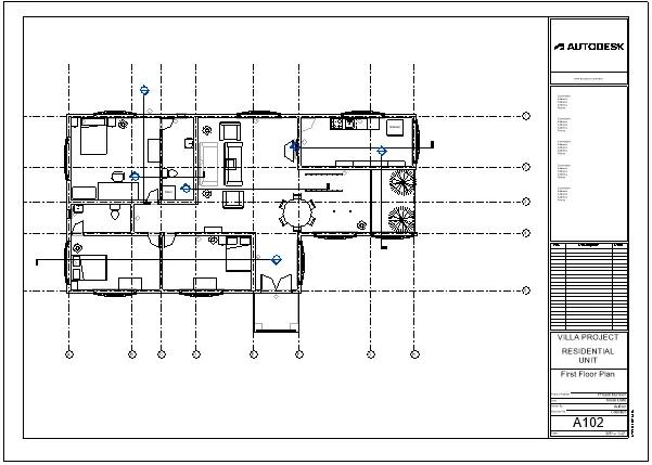
- Then edit the title block as First floor Plan and number as A102. Also edit the name on the Project browser sheet view as A102-First Floor Plan.
c) Add Roof Floor Plan into the sheet.
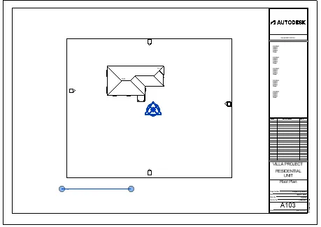
- Then edit the title block as Roof Plan and number as A103. Also edit the name on the Project browser sheet view as A103-Roof Plan.
d)Add Ground Floor Structural Plan into the sheet
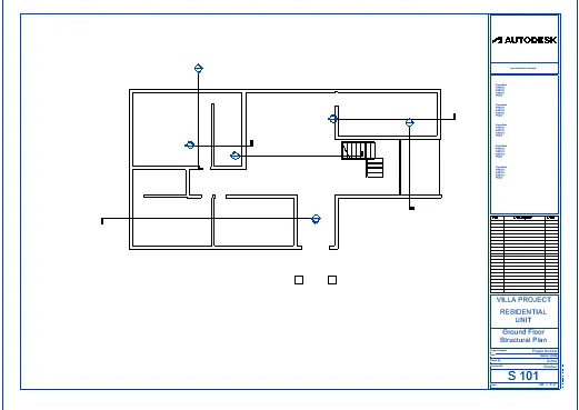
- Then edit the title block as Ground Floor Structural Plan and number as S 101. Also edit the name on the Project browser sheet view as S101-Ground Floor Structural Plan.
e) Add First Floor Structural Plan into the sheet
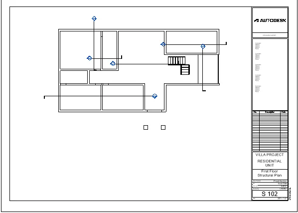
- Then edit the title block as First Floor Structural Plan and number as S 102. Also edit the name on the Project browser sheet view as S 102-First Floor Structural Plan.
g) Add North and South view sections into the sheet
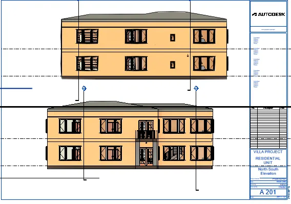
- Then edit the title block as North South Elevation and number as A 201. Also edit the name on the Project browser sheet view as A 201-North South Elevation.
h) Add East and West view sections into the sheet
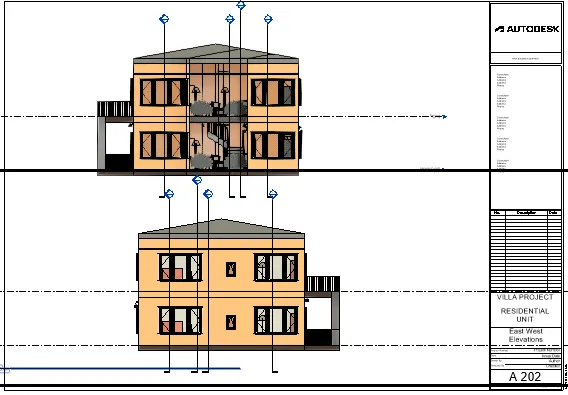
- Then edit the title block as East West Elevation and number as A 202. Also edit the name on the Project browser sheet view as A 202-East West Elevation.
RESULT:
The multiple sheets are created as per the requirements with title blocks.
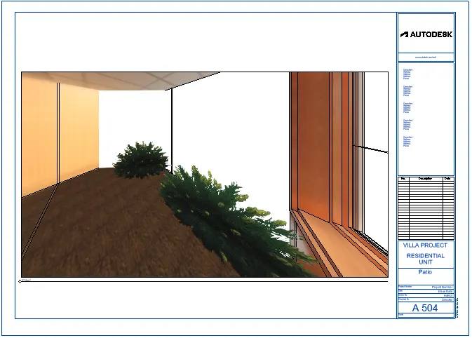
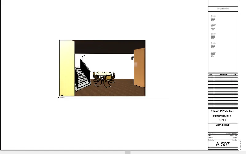
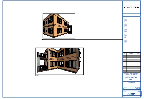
10) Create a camera-specific view or a 3D view in each room ( living, dining, bedroom). Based on the views create a new set of sheets starting A-501 (you can add as many sheets after, 502, 503.. n)to place the 3D view images. Produce the sheets as a part of project drafting.
AIM:
Need to create a camera-specific view or a 3D view for each room in the sheets.
INTRODUCTION:
- Camera views are reallistic view whivh allow aus to view what we see acutually if we were standing at any given location in our design.
- After creating your 3D model in Revit, You can place a camera by activating it from your ribbon, View tab, Create panel. Click the small arrow near the 3D view, and click the camera button on the drop-down menu.
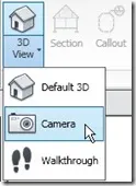
Then you can define the camera by two clicks: the camera position and target position. After you define the camera, Revit will automatically open a new view. This view will show you what your camera sees. Mostly we need to modify the view. Make sure modify is active, click the view boundary. You will see the blue grips on the rectangle sides. You can resize the boundary by dragging the grip.
PROCEDURE:
- First go to the plan view, place the camera in the bedroom to desired direction as follows.
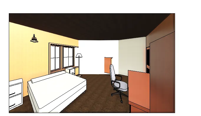
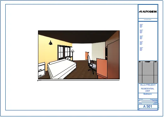
a)Then add this 3D view into the sheet with title block as A-501 Bedroom.
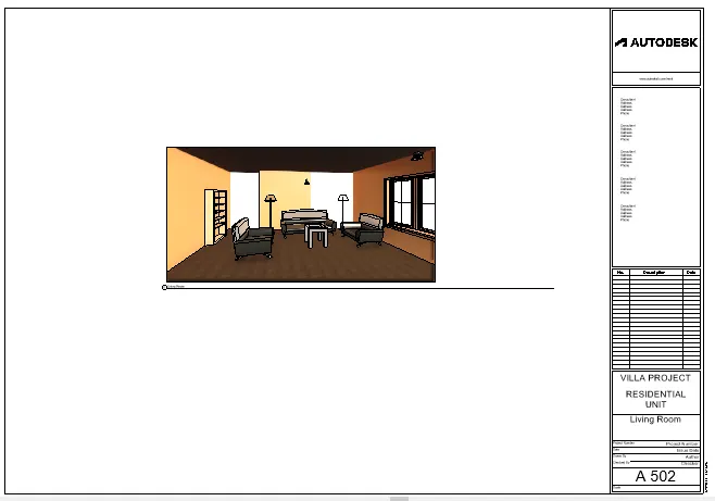
b) Place the camera into the living area.
Then add this 3D view into the sheet with title block as A-502 Living Room.
c) Place the camera into the toilet.
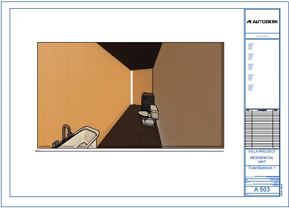
Then add this 3D view into the sheet with title block as A-503 Toilet Bedroom 1.

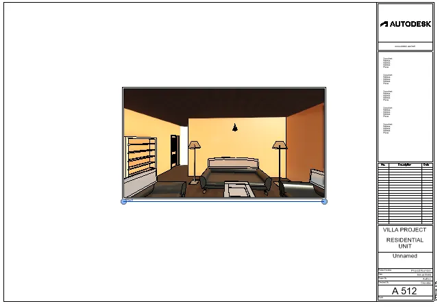
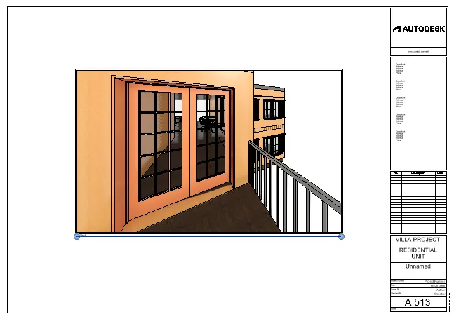
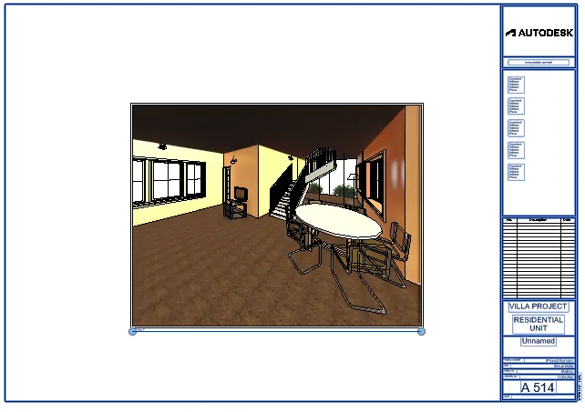
RESULT:
The camera views created are placed in different sheets a shown.