Creating Levels, Grids, Layout and model elements for a residential unit using REVIT
1) AIM: Need to know about BIM, its features and benefits.
INTRODUCTION:
Building Information Modeling (BIM) is the holistic process of creating and managing information for a built asset. Based on an intelligent model and enabledby a cloud platform. BIM integrates structured, multi-disciplinary data to produce a digital representation of an asset across its lifecycle, from planning and design to construction and operations.
BIM is the foundation of digital transformation in the architecture, engineering, and construction industry. As the leader in BIM, Autodesk is the industry's partner to realize better ways of working and better outcomes for business and the built world. It is the latest evolution of the building industry and it refers to the process of designing, building and operating a building collaboratively using a single coherent system of 3D models rather than seperate design drawings.
Features of BIM:
- Centralize document management
- Design and visualize a 3D model
- Create automated reports on all workflows
- Manage and track resources
- Monitor and manage construction costs
- Detect and resolve clashes
BIM software is a valuable tool as it increases visibility into ongoing construction projects. It also allows for more streamlined planning and better resource management.
For these reasons, more organizations are now turning to building information modeling software.
Benefits of BIM:
- Improve Onsite collaboration and communication: Digital BIM models allow for sharing, collaborating, and versioning that paper drawing sets dont. With clou-based tools such as Autodesks BIM 360, BIM collaboration can seamlessly occur across all disciplines within the project.
- Model-Based cost estimation: MAny firms are realizing that including estimators earlier in the planning stage allows for more effective construction cost estimation, which has led to the growth of model-based cost estimating (also known as 5D BIM).
- Visualize Projects in Preconstruction: You can plan and visualize the entire project during preconstruction, before the shovel hits the ground. Spcae-use simulations and 3D visualizations allow clients to experience what the space will look offering the ability to make changes before construction start. Having a greater overview from the beginning minimizes expensive and time-consuming changes later.
- Better Coordination and Clash detection: BIM allows to better coordinate trades and subcontractors, detecting any MEP, internal or external clashes before construction begins.
- Mitigate Risk and reduce cost: Closer collaboration with contractors can lead to reductions in tender risk premiums, lower insurance costs, fewer overall variations, and ferwer oppurtunities for claims. many companies are using BIM and construction technology to reduce costs and mitigate risk.
- Improved Scheduling/ Sequencing: In the way that many of these benefits save money, they save time by reducing the time of project cycles and eliminating construction schedule setbacks.
- Increase Productivity with Prefabrication: BIM data can be used to instantly generate production drawings or databases for manufacturing purposes, allowing for increased use of prefabrication and modular construction technology.
2) AIM: Concepts of categories, families, elements and instances in Revit.
- Categories: Families in Revit are divided into categories such as annotation symbols, ceilings, columns, doors, windows and so on. Expand the Families branch in the Project Browser to see these categories. It cannot be created or deleted and are important in determining the visibility of elements.
- Families: The 3 kinds of families in Revit are: system families, loadable families and in-place families. Most elements that create in your project system families or loadable families. Loadable families can be combined to create nested and shared families.
- Elements: Revit uses 3 types of elements in projects: model elements, datum elements and view-specific elements.
- Windows, doors and cabinets.
- Beams, braces and structural columns.
- Sinks, boilers, ducts, sprinklers and electrical panels
4. Instances: An item from a catalog that is installed in your facility where the properties for the asset are unique to its installation.
For example by loading families the Doors , windows , Duct, Furniture etc are all Categories.
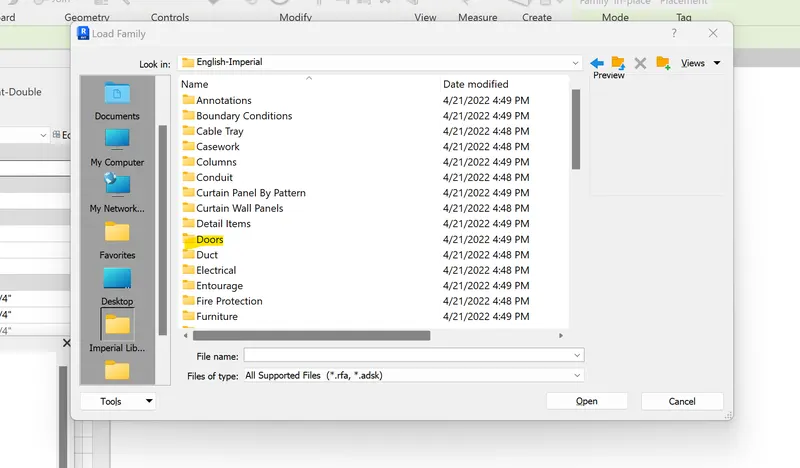
If am selecting Doors Commercial, Hardware, Residential are families.
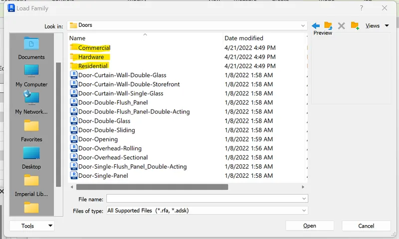
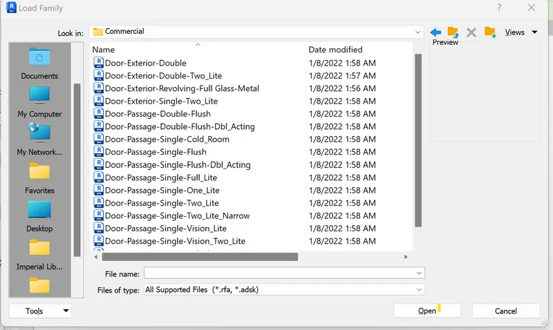
Inside these families are called elements. For example if am selecting Commercial the below shown are elements of these family.
3) AIM: Need to setup a project and the save the file. Make the project Imperial/ metric form. Need to give project information and set maximum backups project file to 3.
PROCEDURE:
- To setup a new project, open revit software and make a new project with template given as Imperial Architecture and press OK.
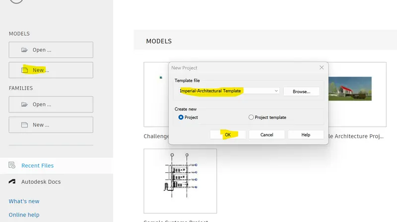
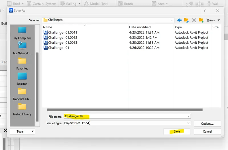
- Then save the file as appropriate name (given as Challenge- 02)
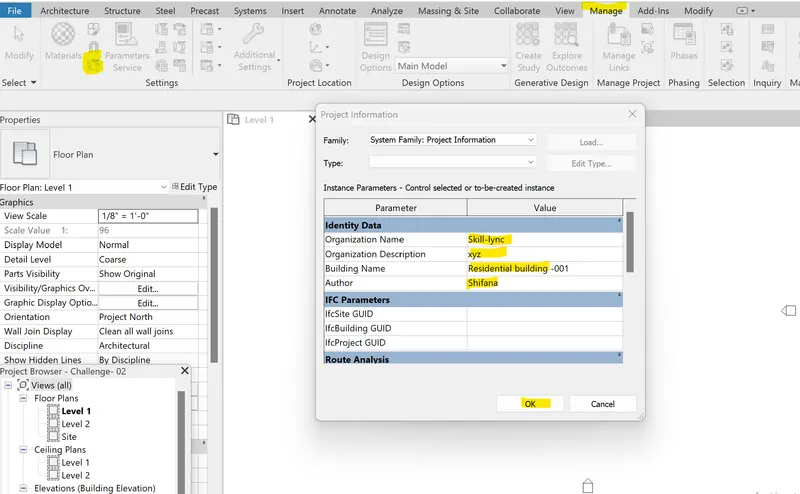
- From Manage tab give project information with definite datas and press OK.
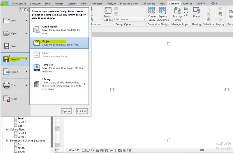
- For setting up maximum backup files go to File menu, pick save as option and select project.
- From the dialogue box select the "Options" as shown below and from there set as maximum backups as 3 and press OK.
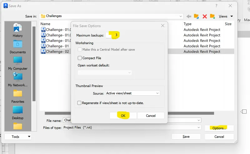
RESULT: Saved the new project with appropriate name , gave project information and setup the maximum backup files as 3.
4) AIM: Need to know the concepts of levels and grids
PROCEDURE:
For setting the levels we need to be enabled in elevation view.
- From the architecture template, double click on any elevation view from project browser. So we can see the two levels as level 1 and level 2 at 10' offset distance as shown below.
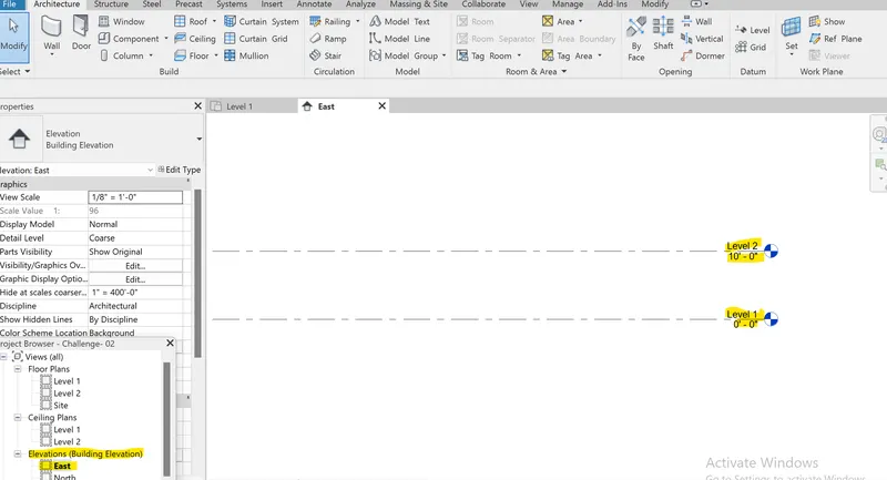
- Rename the Level 1 by double clicking as Ground floor and provide YES for the dialogue box appearing. Similarly the Level 2 as First floor. Provided offset for the 2 levels default as 10'.
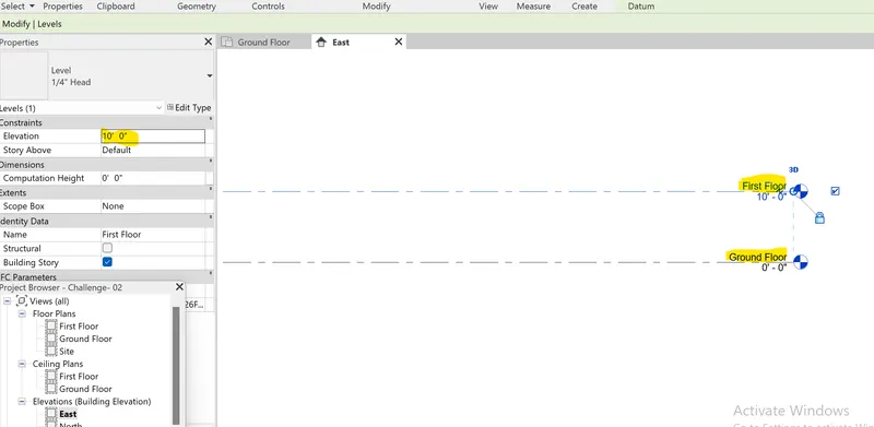
- For creating 2 more levels from Architecture view select level option and there are two options line and pick line option.

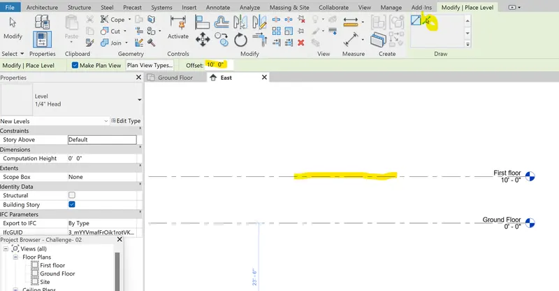
- Select the pick line option and provide offset as 10'. Then select existing level as marked above. So a level appeared as level3 and click one more level as level 4.
- Rename level 3 as Second floor and level 4 as Roof.
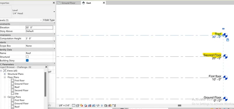
For setting up the grids we need to do on any levels. Here I have chosen First floor from project brower.
- From the architecture view select grid option

- There are 4 options on Grid view as line, start end radius arc, center ends arc and pick lines.

- Use line option and pick two points transverse directions for drawing transverse grids. So the first grid line is appeared.
- Then slect pick line option and select the reference grid option we made and give the offset as 10'.
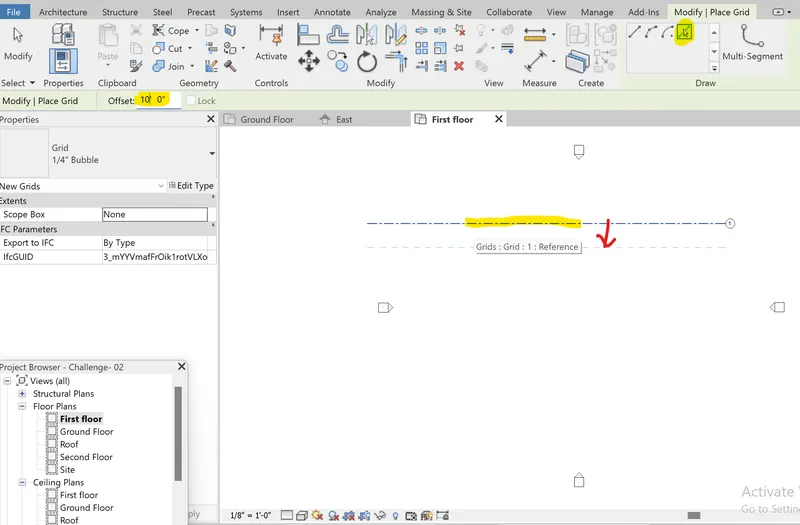
- Similarly provide 3 more grids.
- So the grids appeared as 1, 2, 3, 4 and 5. Rename 1 by double clicking as A, 2 as B, 3 as C, 4 as D, 5 as E.
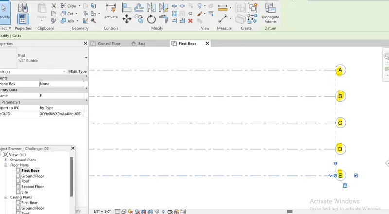
- For providing longitudinal grids again select grid option and select line tool. Then place the line longitudinally to the transverse grids
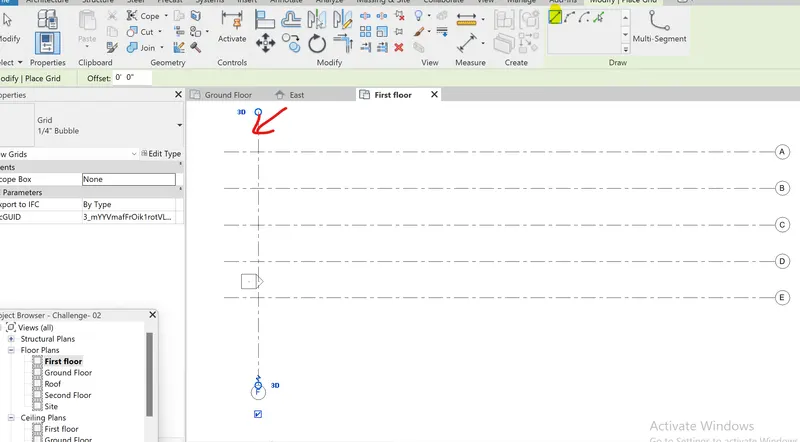
- As transverse grids select pick line option and provide offset as 10'. Then draw 10grids longitudinally
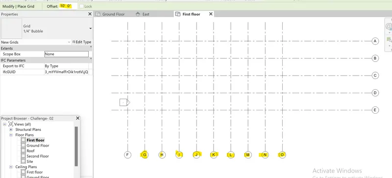
- Rename the F grid as 1, G as 2, H as 3,.... O as 10
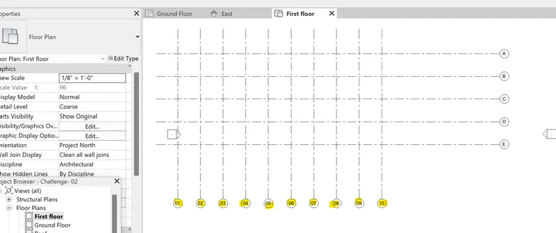
RESULT: In this we have set the levels and grids with definite offset and renamed them as appropriately.
5) AIM: Need to draw the layout of a residential unit.
PROCEDURE:
- Drawn the layout of a residential unit with appropriate dimensions and with necessary needs.
- From architecture menu walls are drawn .
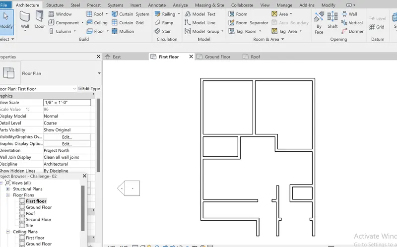
RESULT: Architectural layout is created by using Revit software.
6) AIM: Need to give dimensions for the layout and add necessary components.
PROCEDURE:
- For dimensioning the layout, from annotate tab there are 3 options such as Aligned, Linear and Angular.
- Select Linear for horizontal dimensioning from annotate tab.
- Pick the inner corner of the first room for dimensioning as shown below.
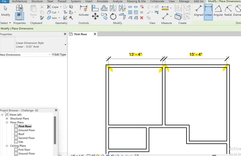
- For vertical dimensioning select the aligned dimensioning from annotate tab and select the inner corners of the wall. It will automatically aligned based on the roofs.
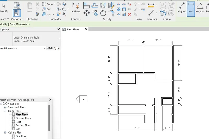
- Dimensions are provided as shown above.
- For placing the doors and window components, first need to insert the doors.
- From Architecture view, click on doors select one door type from properties and place the doors over desired space.
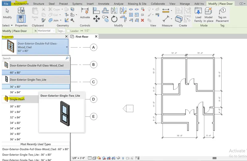
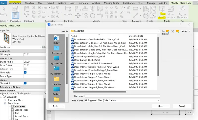
- Place every door upon our preferences. If we want to load more doors, from architecture select doors so load family will appear. From there select doors and there are different types of doors available. Select the appropriate model and place the element into the layout.
- Similarly place the windows to the desired space.
RESULT: Dimensions are given to the layout also provided the doors an dwindows to the appropriate space.
7) AIM: Need to provide the components such as bed, table, lighting, chair, couch to the existing layout.
PROCEDURE:
- For placing a component from architecture view select component and click on place a component.
- For placing bed from component select Load family option and there are so many categories, select the furniture family and select the Bed from this. We can choose different varieties of beds and provide the size also.
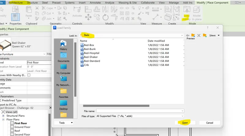
- After selecting the bed we can place to the desire place.
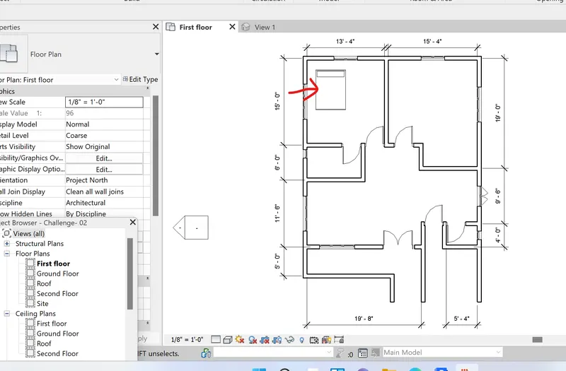
- Similarly i placed Dining table, Lighting, Table, Chair, Coutch, sink, Bathtub as our wish.
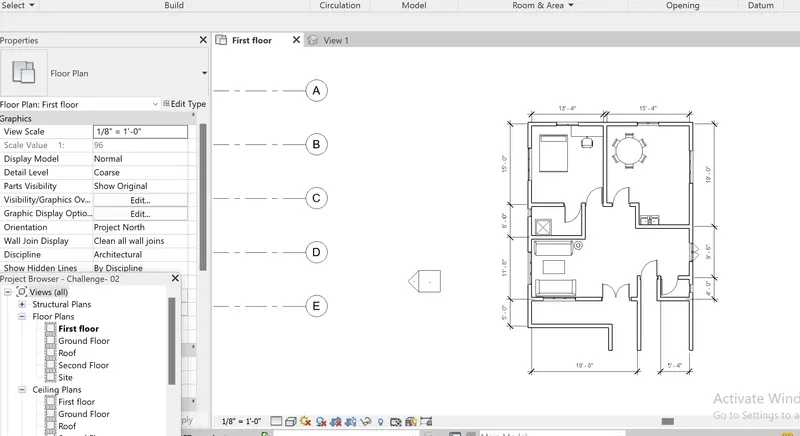
RESULT: We can add any components from the Architectural Load family option as our wish.