Introduction to REVIT concepts
AIM: Introduction to REVIT concepts
INTRODUCTION: The main aim of this whole challenge is to give a brief introduction about each menu bar and panel and sections of the whole Revit 3D software and its concepts. Here there are in total of 13 questions given which are all regarding the different sections or menubars of the Revit 3D software. The ways of using it are asked. The procedure, snips, and results for each question are given below.
QUESTION:
1) From the file menu, create a new project (Structural / Architectural / Construction template ) and name the project appropriately
Procedure:
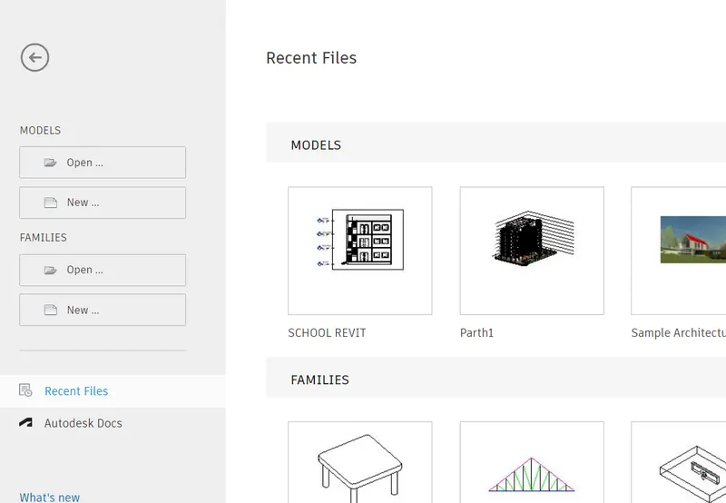
- Open Revit software on the PC.
- As the software opens up, it will ask a few things about what type of project it is, and what type of template we want? etc, etc.
- Just ignore those and click on the arrow given above that.
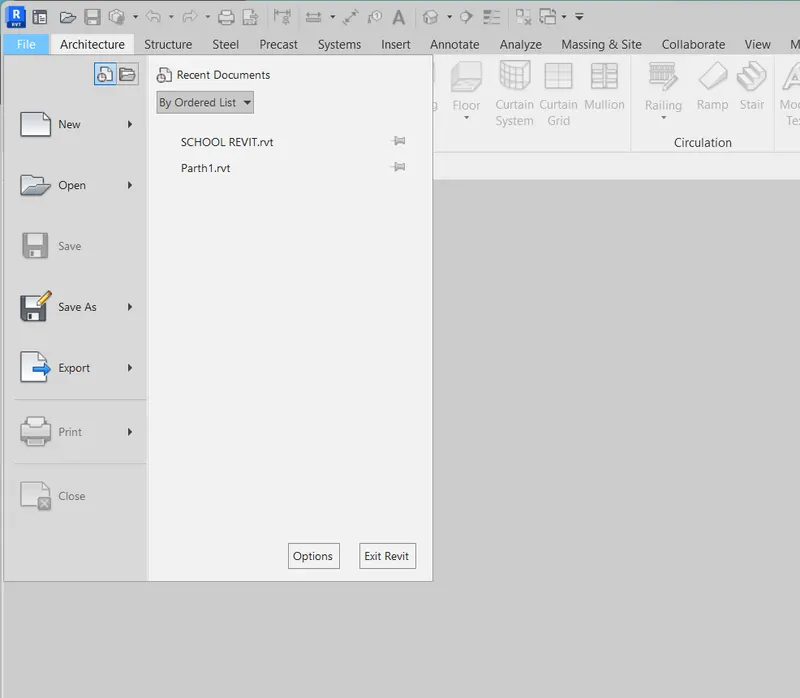
- Now once the next window opens, click on the file menu.
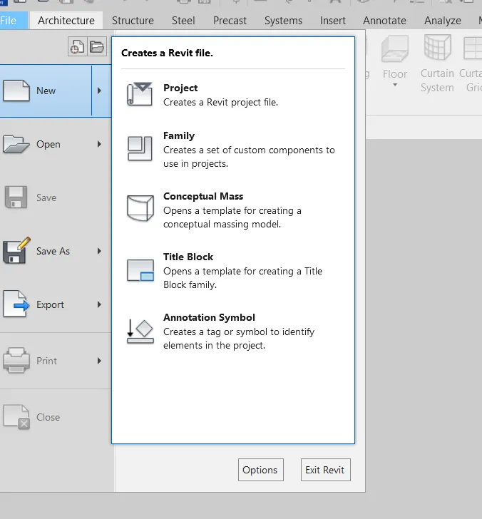
- In the drop-down list click on the new option.
- Click on the project.
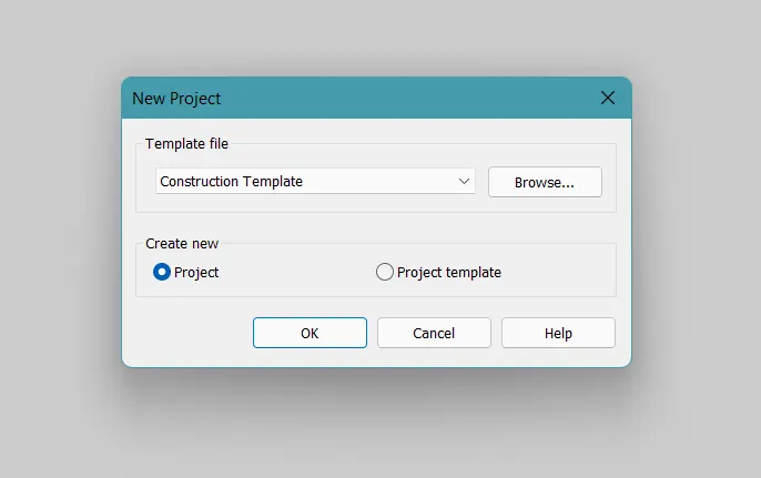
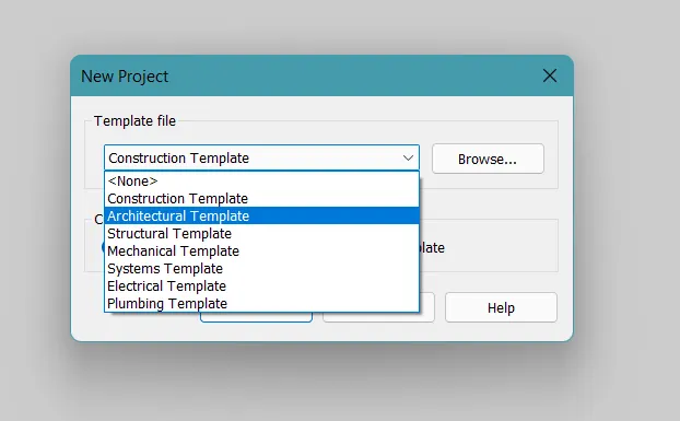
- Once you click on the project option, a dialog box appears which asks about which type of project would like to make.
- For example, I am clicking on the architectural one here.
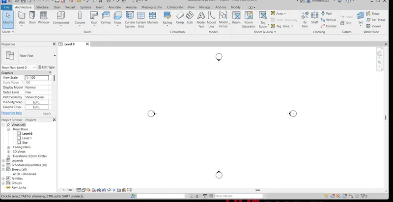
- Thus a new architectural project sheet is created.
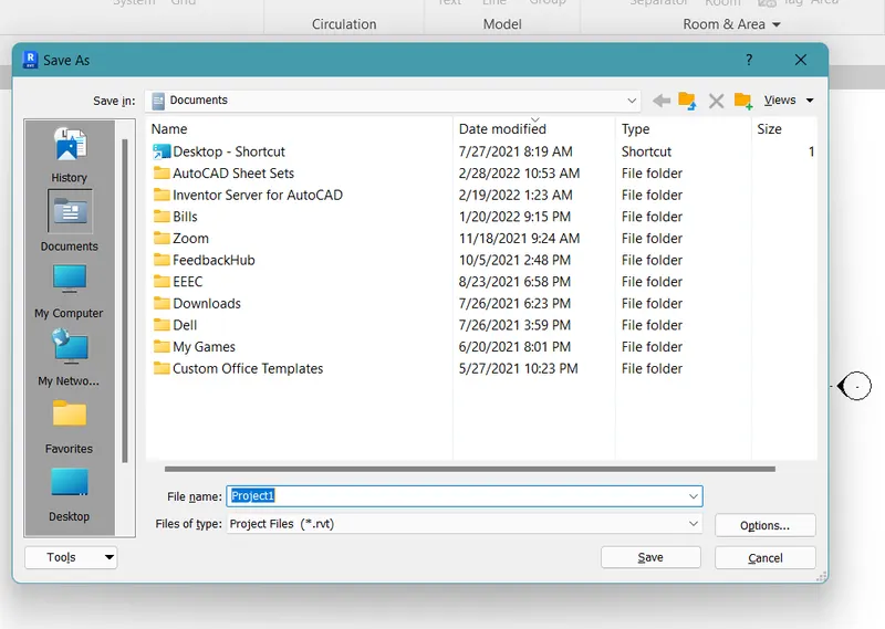
- Now click ctrl+s to save the file.
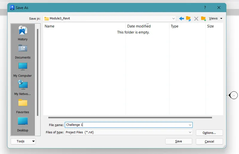
- Save the file in the desired location with the name "Challenge 1".
- Thus the file is created and saved.
- Please have a look at snips for better clarity.
Results: A new project file is created from the file menu and saved as asked in the challenge.
Snips:
2) Save the new project file. Close and open using icons from the file toolbar
Procedure:
- As shown in the above question a new file was created from the file menu.
- Now it was saved by using the ctrl+s command.
- The name of the file was given as "Challenge 1".
- Once the file is saved close the whole Revit and open it again.
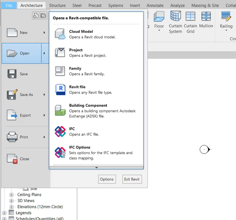
- Now click the arrow given above on the first page and go to the File menu.
- Now click on the open option.
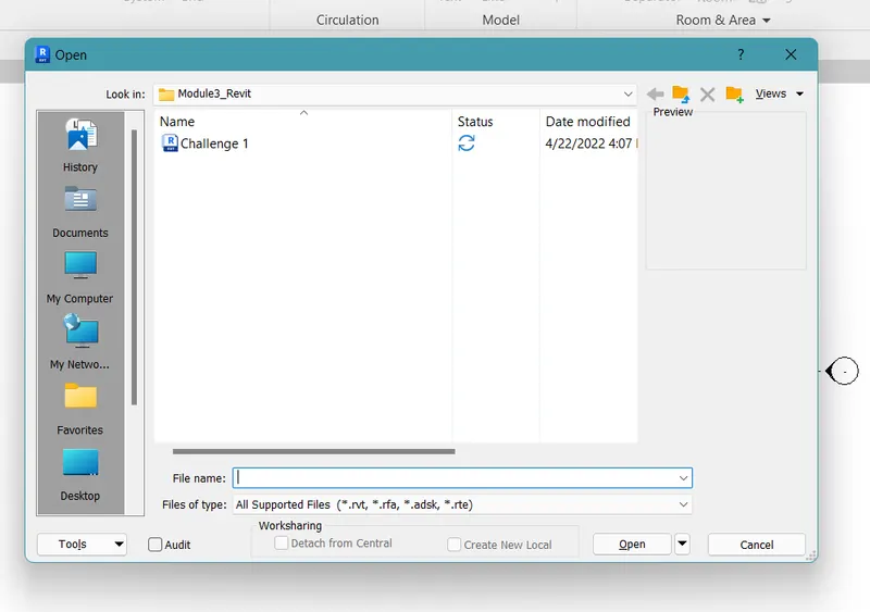
- Now find the file whichever you want to open and click on that.
- Thus the new file is opened using the open section of the file menu.
- Please have a look at the below snips for more clarity.
Results: The new file created in the question one is now opened again using the open icon in the File menu,
Snips:
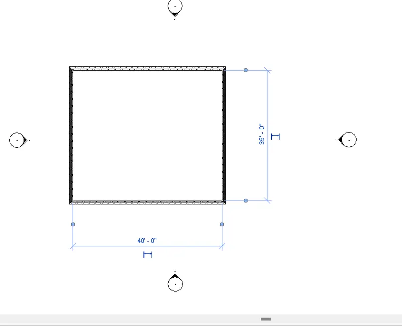
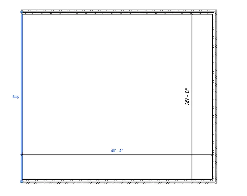
3) From the architecture/ structure toolbar familiarize yourself with options to draw a wall. Create a rectangular layout of walls of about 40’-0” X 35’-0”
Procedure:
- Open the new file which was created in question 1.
- Now go to the architecture menu.
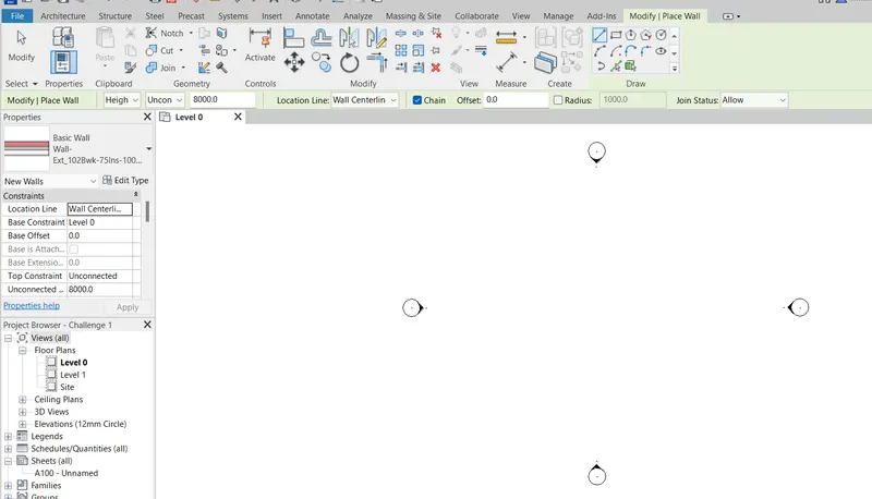
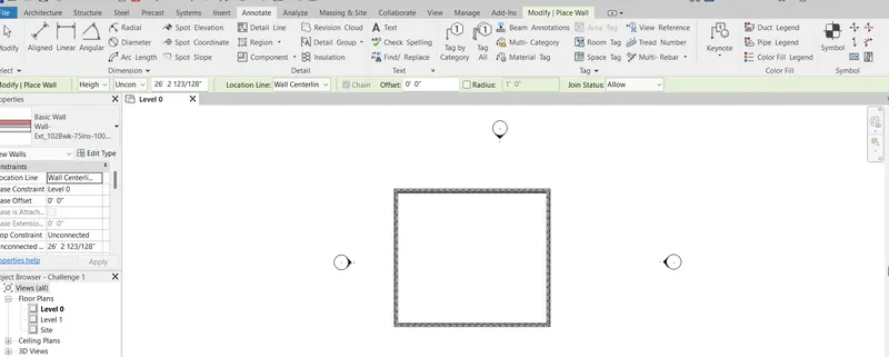
- To create a rectangular layout of a wall, click on the wall command icon in the architecture menu.
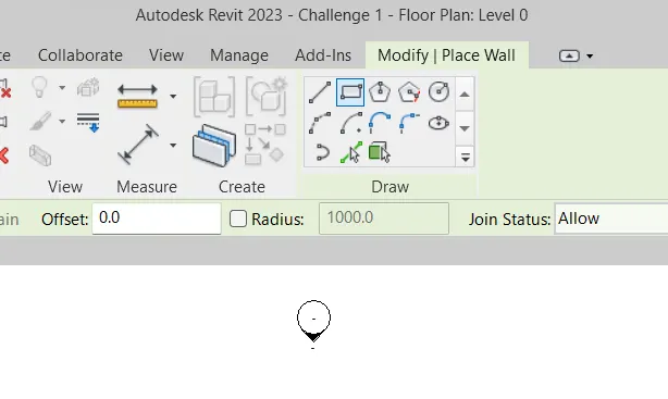
- Now after clicking on the icon, click on the rectangle option in modify section.
- Now in the drafting section, draw the rectangle of the given dimensions.
- Thus a rectangular layout of a wall of asked dimensions is created.
- Please have a look at the below snips for more clarity,
Results: A rectangular layout of the wall of asked dimension is created using the wall command.
Snips:
4) From the Annotate toolbar use the aligned option to add dimensions to the layout
Procedure:
- Now as the layout is drawn as shown in the upper question, we will move forward to give its dimensions.
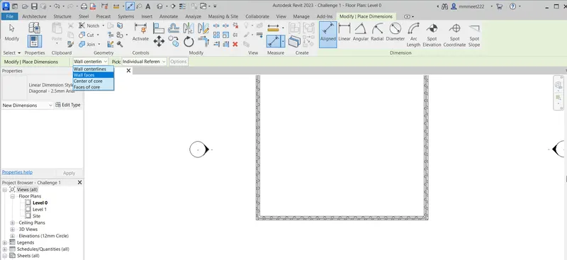
- For that go to annotate tab in the menubar and click on the aligned dimensions.
- Then in a drop-down list click on the wall faces option given just above the drafting section.
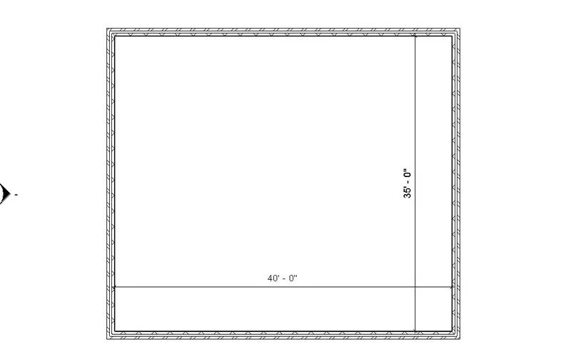
- Now click the first face from where you want to start the dimensioning and then click the second face of the wall to get the distance between the two walls.
- Give the dimensions wherever necessary.
- For more clarity, please have a look at the below snips.
Results: The dimensions of the wall are given.
Snips:
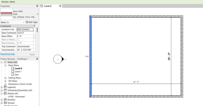
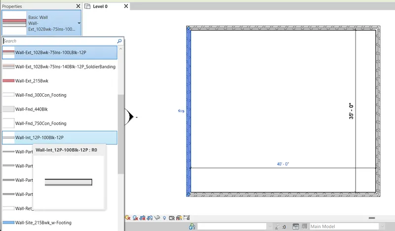
5) Use the properties browser to switch to different wall types
Procedure:
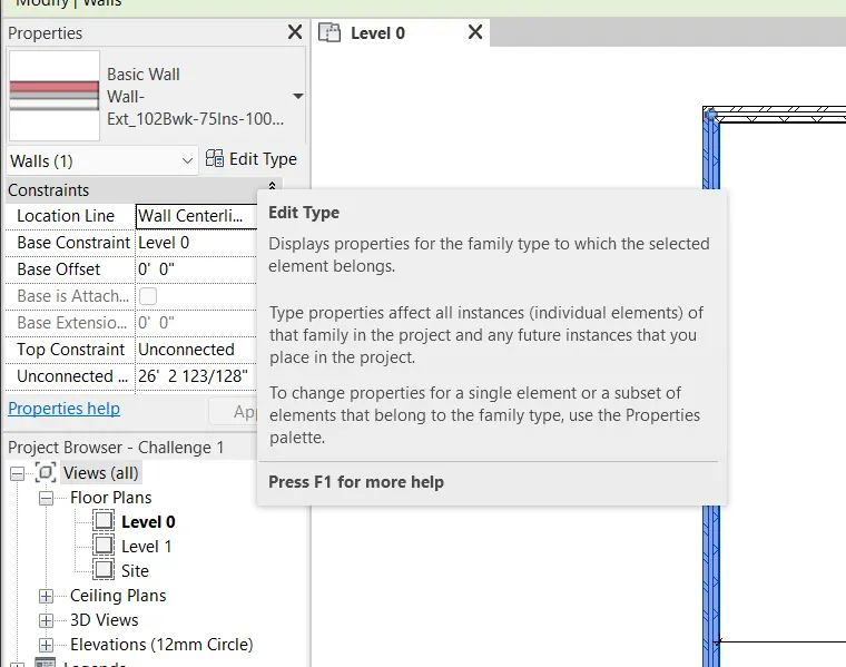
- To change the type of a wall, click on any wall whichever you want to change the properties of.
- Now go to the property section given on the left side of the screen.
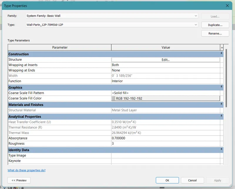
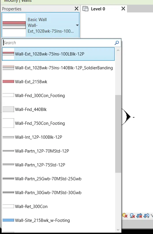
- One can edit the properties from the edit type or also from the drop-down list.
- Now, going forward with the dropdown list.
- Click on the wall type to which you wish to change the current wall.
- Thus, the wall is changed.
- Have a look at the below snips for more clarity.
Results: The properties of the wall were changed using the property tab in the Revit.
Snips:
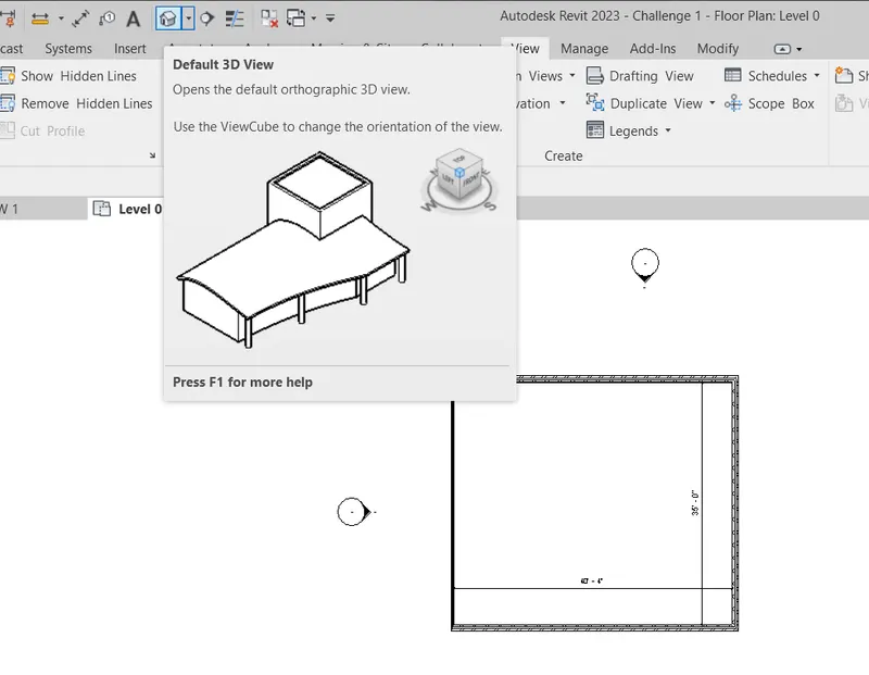
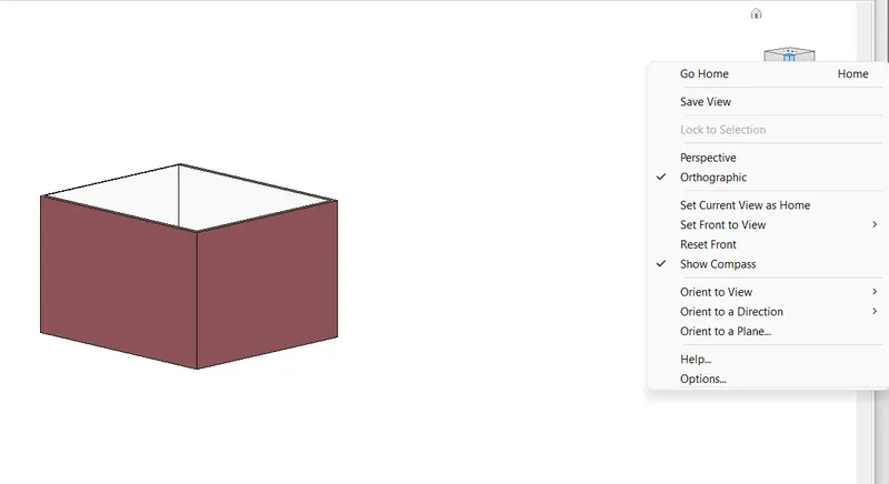
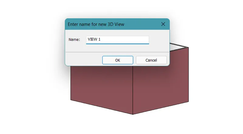
6) Create a 3D view from the view toolbar and save the view with the appropriate name
Procedure:
- Once the whole layout is created, we have to save 3D views.
- To save the 3D views click the hut or house icon shown in the topmost bar.
- Now right click on the cube after adjusting the desired view of the building and click on the save the view option.
- Create the view by giving the desired name.
- These views can be seen in the section below the property bar under the views section.
- For more clarity have a look at the below snips.
Results: A 3D view of the structure was created and saved with an appropriate name.
Snips:
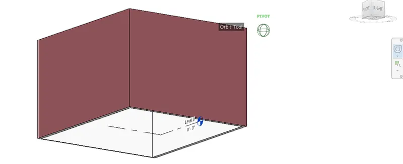
7) Navigate through the 3D model using the view cube. Orbit/pan through the model layout created
Procedure:
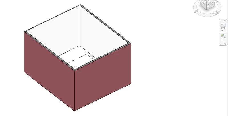
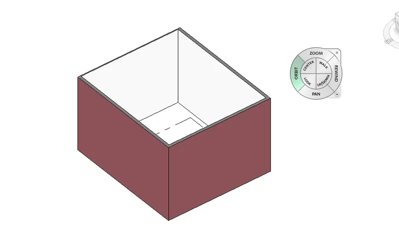
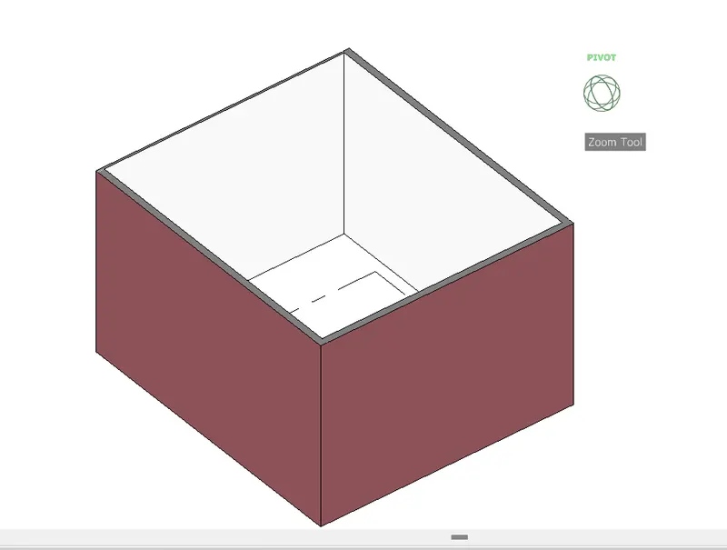
- Now below the 3D cube, there is a bar that has different tools.
- Using that tools one can orbit, zoom, pan, etc the whole structure.
- For more clarity have a look at the below snips.
Results: An exposure to the use of different tools was given.
Snips:
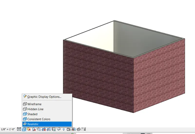
8) Use the visibility settings option below to switch models to shaded, realistic, hidden lines options
Procedure:
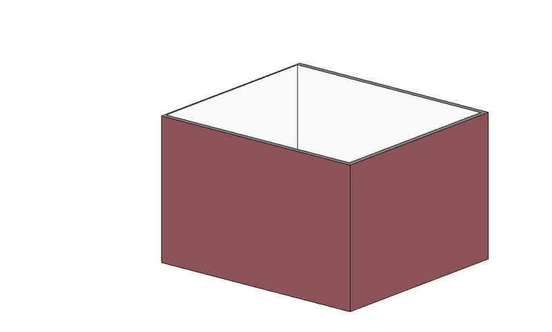
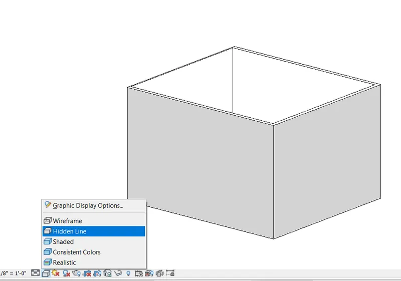
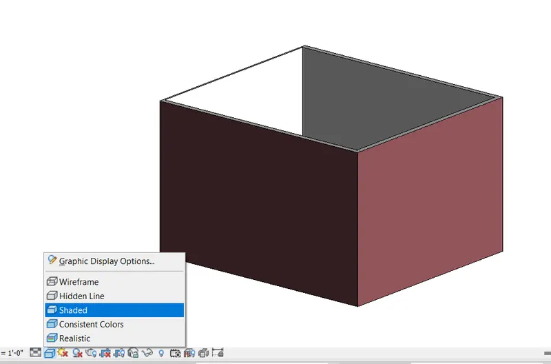
- To change the type of structural view select the cube icon which is given in the bottom-most bar.
- When clicked on that a list opens which has different types of views.
- Click on the one whichever is required.
- For more clarity have a look at the below snips.
Results: Different visibility options were explored.
Snips:
9) Turn the sun path on and off to view shadings in the layout created
Procedure:
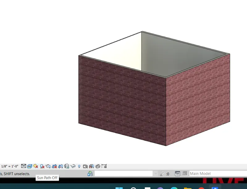
- The sun is the natural lighting that is required at the time of rendering.
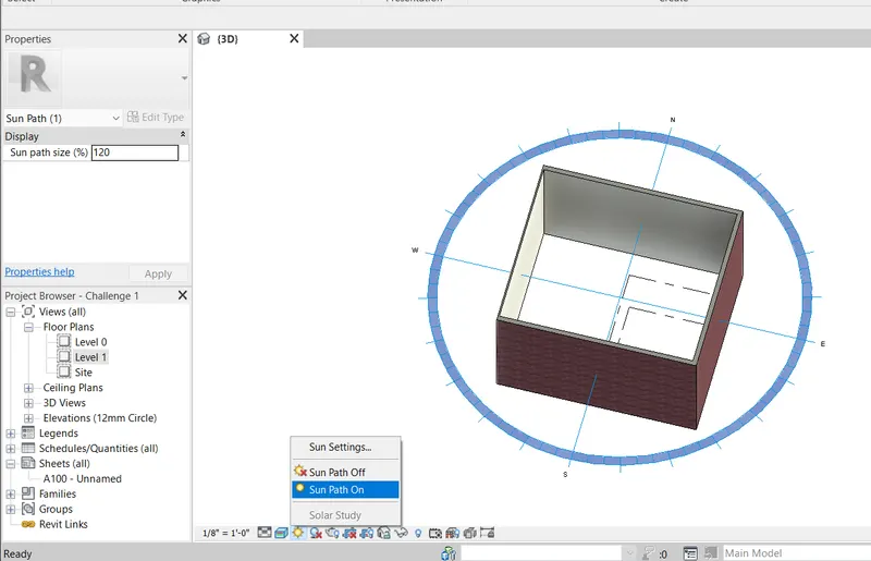
- To turn off and on the sun, we need to click on the sun icon which is given just beside the cube icon which was used to change the visibility setting.
- When clicked on that the list asks whether to turn on or turn off the sun.
- Click on the turn on and you will see a compass-like thing appear, which will show the direction.
- For more clarity have a look at the below snips.
Results: The sun can be now turned on/off easily to view shadings of the layout created.
Snips:
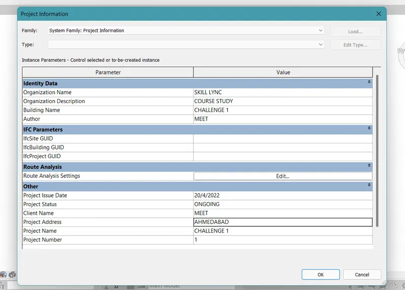
10) Use the Manage toolbar to enter project settings, project name, and project issue date (choose according to your convenience).
Procedure:
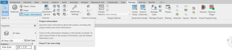
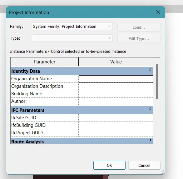
- To add the project details, go to the manage tab of the menubar and click on the project information command icon.
- A dialog box will appear.
- Add the necessary details and press OK.
- Thus the project details are added.
- For more clarity have a look at the below snips.
Results: The manage tab is used to add project information
Snips:
11) What is the Analyze toolbar used in Revit? How it is beneficial for design and modeling
Answer: The analyze toolbar is used to analyze the whole structure of the building. When one creates a structure there are many different kinds of forces, loads, and designs that are taken into consideration. A small failure can lead to the failure of the whole building. This analyze tab of the Revit software helps in analyzing if the structure is proper or not. Checks all the loads and gives the results for better designs as well and also gives the reasons why is the design not correct!
12) What are the links that Revit supports to be linked to the model?
Answer: Linking models are primarily intended for linking separate buildings, such as those that compose a campus. You can link architectural models, structural models, and MEP models. For example, the following site plan shows 4 building models linked to one model. When you link a model into a project, Revit opens the linked model and keeps it in memory. The more links a project contains, the longer it can take to open. Linked models are listed in the Revit Links branch of the Project Browser. You can convert linked Revit models to groups, and you can convert groups to linked Revit models. You can also mirror linked Revit models.
13) Why do you need the Collaborate tab in Revit? How it supports modeling and its efficiency
Answer: Revit is not just software that is used for architectural or structural purposes, but also electrical, and mechanical purposes as well. When an architectural drawing is made, the drawing is also shared with other professionals so that the works regarding different respective fields are also carried on simultaneously. Thus all the fields work together to give the final draft together as a team. This is where the collaborate tool is most used