Introduction to REVIT concepts
CHALLENGE 1
Introduction to REVIT concepts
AIM:
To identify and demonstrate the basic tools, its functions and explain the procedure step by step.
INTRODUCTION:
Revit is a BIM (Building Information Modelling) software to drive efficiency and accuracy across the project lifecycle, from conceptual design, visualisation and analysis to fabrication and construction.
Begin modelling in 3D with accuracy and precision.
Automatically update floor plans, elevations and sections as your model develops.
PROCEDURE:
1) From the file menu, create a new project (Structural / Architectural / Construction template ) and name the project appropriately.
- Open the REVIT Software.
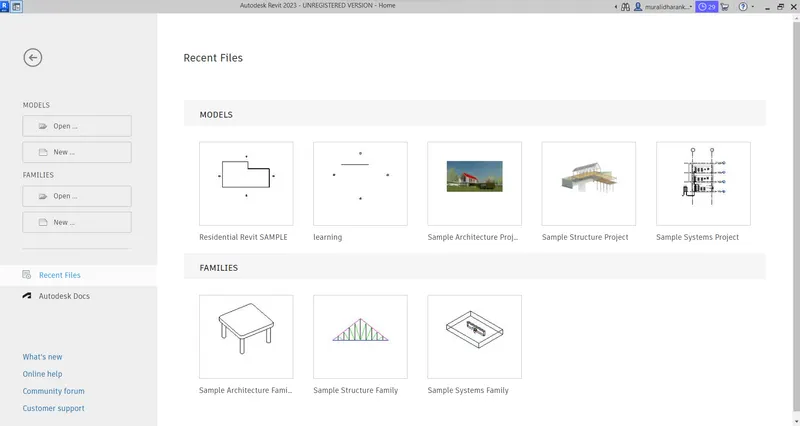
- Choose NEW from the models tab.
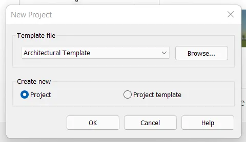
- Select ARCHITECTURAL TEMPLATE and give ok.
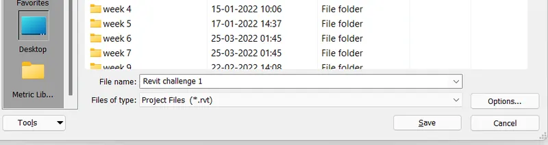
- Go to file, select save option and save the project as Revit challenge 1 as shown in figure.
2) Save the new project file. Close and open using icons from file toolbar.
- Go to file, select save option and save the project as Revit challenge 1 as shown in figure.
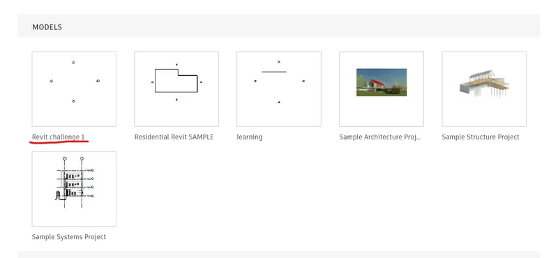
- Now, close the model.
- From the toolbar select the model which was saved before as Revit challenge 1 to open it.
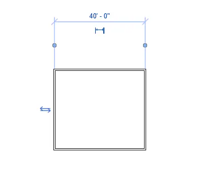
3) From the architecture/ structure toolbar familiarize with options to draw a wall. Create a rectangular layout of walls of about 40’-0” X 35’-0”.
- Choose Architecture tab from the toolbar.
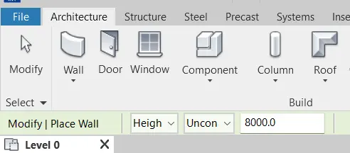
- Select the wall icon and create a rectangular layout of 40'x35'.
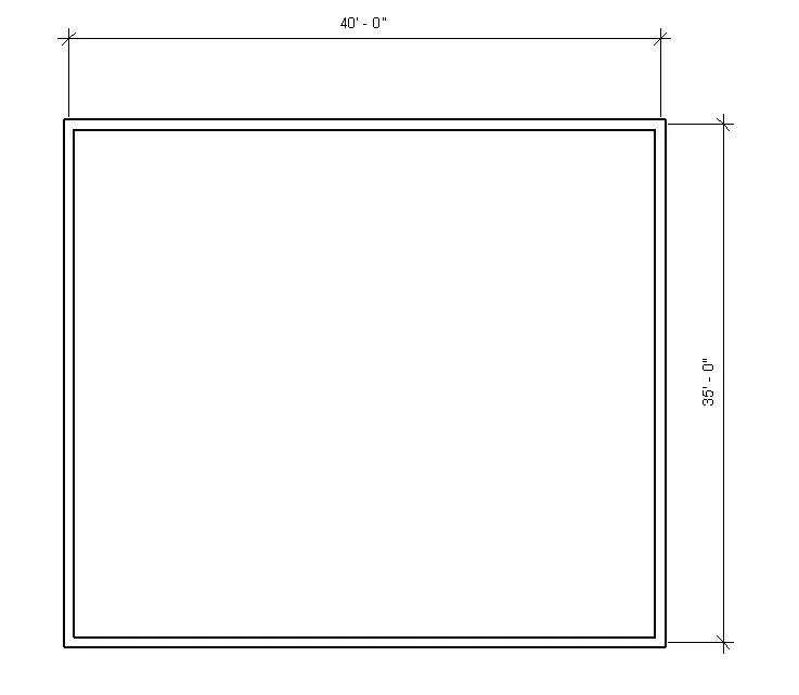
4) From the Annotate toolbar use the aligned option to add dimensions to the layout.
- Choose ANNOTATE option from the toolbar.
- Select ALIGNED icon to mention the dimensions for the layout.

- Now, carefully select the corners which needs to be measured.
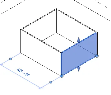
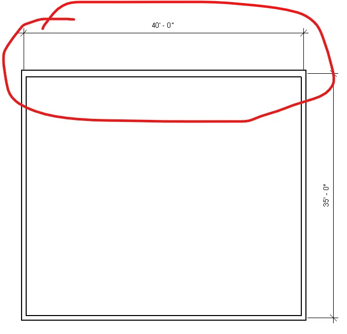
- A 3D view of the layout wall and dimension marked is shown.
5) Use the properties browser to switch to different wall types.
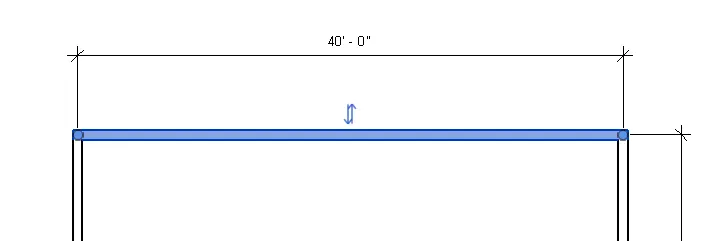
- A 40' basic generic wall of 8" is shown in the image.
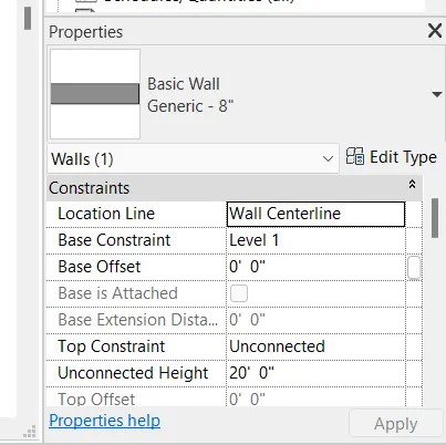
- Properties of the wall before change. An 8" basic generic wall is used.
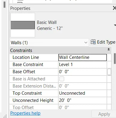
- Now, the above selected wall is changed to 12" basic generic wall in the properties manager.
- The image shows the 12" basic generic wall of 40'.
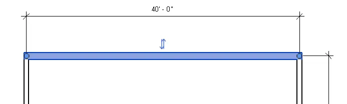
- The marked portion shows the image after changing the properties from 8" wall to 12" wall.
6) Create a 3D view from the view toolbar and save the view with the appropriate name.
- Choose VIEW option from the toolbar and select 3D VIEW icon.
- The plan now changes into a 3D view as shown below.
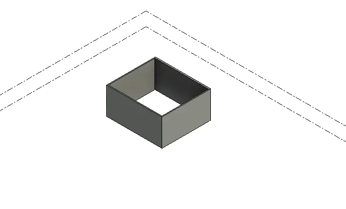
- Choose the desired view from the VIEW CUBE which is located in the top right corner of the model window.
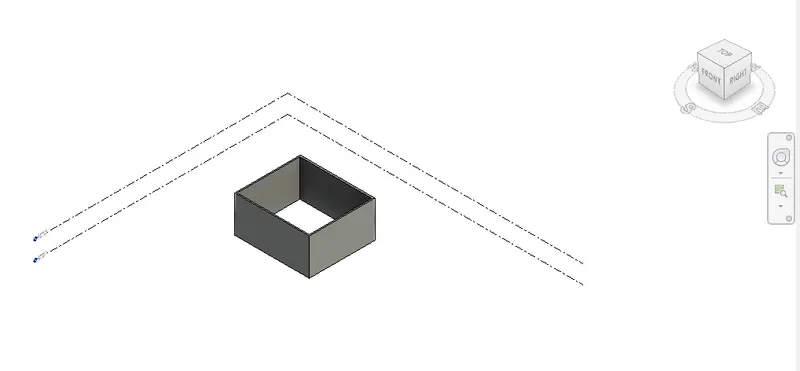
- Right click the desired view from the VIEW CUBE.
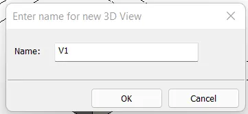
- A dialogue box opens up as shown.
- Give a name to the view as you like. Here, I have given the name as V1.
- This time I have changed the view angle to front view.
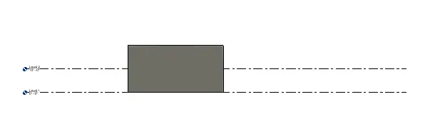
- And, right clicked the view cube and saved the view as V2.
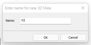
7) Navigate through the 3D model using the view cube. Orbit/pan through the model layout created.
- Go to VIEW option.
- Choose USER INTERFACE icon and enable the navigation bar.
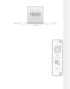
- Select the navigation wheel.
- There are multiple options like ORBIT,PAN,ZOOM, etc..
- Select ORBIT to change the orbit.
- Select PAN to drag the model.
8) Use the visibility settings option below to switch model to shaded, realistic, hidden lines options.
- Select the VISUAL STYLE icon in the bottom left .
- The icon is marked in red color.
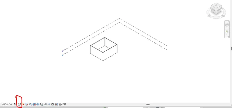
- There are number of view types like WIREFRAME,HIDDEN,SHADED,REALISTIC etc..
- Here, I have chosen SHADED.
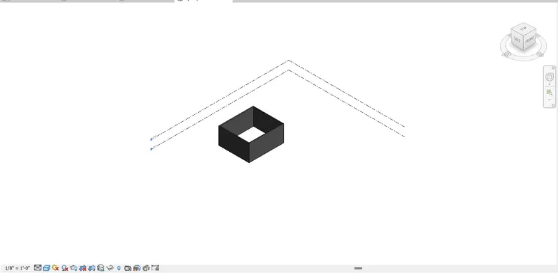
- This is the REALISTIC view of the layout model.
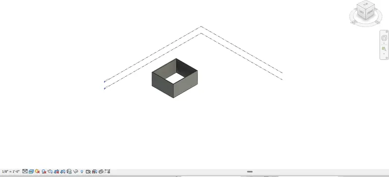
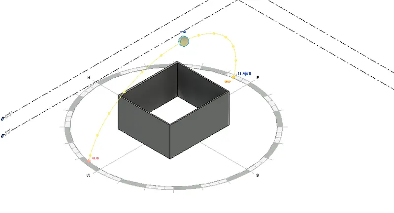
9) Turn the sun path on and off to view shadings in the layout created.
- Go to manage option in the toolbar.
- Select LOCATION ICON and enter the location as chennai.
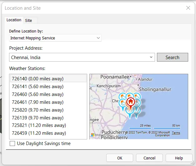
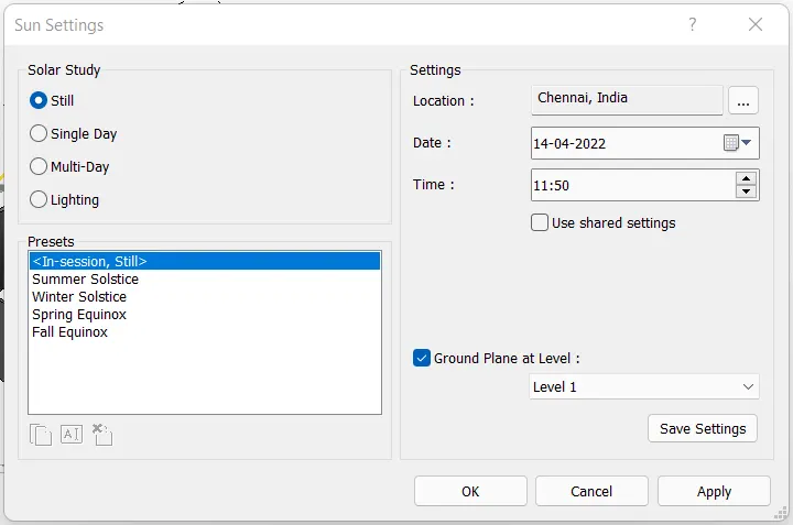
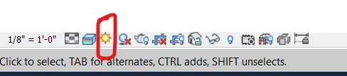
- Now, from the bottom left corner, choose the SUN icon.
- And, select the sun path on.
10) Use the Manage toolbar to enter project settings, project name, and project issue date (choose according to your convenience).
- Go to manage toolbar.
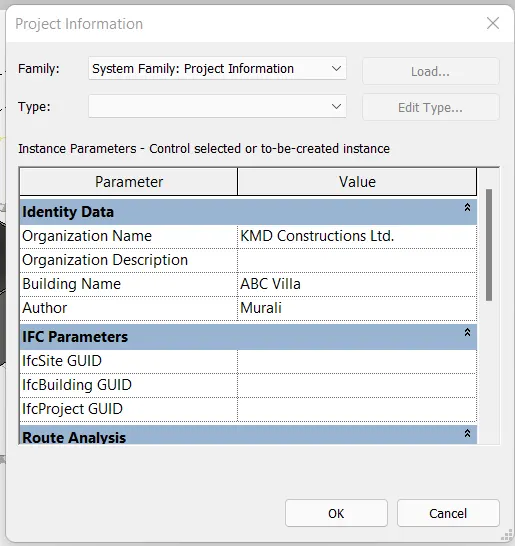
- Select the Project Information.
- Edit the datas as required.
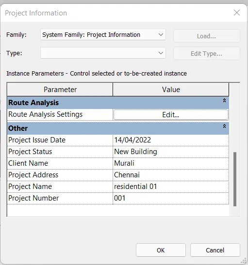
- Organization name is given as KMD constructions Ltd.
- Building Name as ABC Villa.
- Project issue date as14/04/2022.
11) What is the Analyze toolbar used in Revit? How it is beneficial for design and modeling.
- It can be used to perform structural analysis of the building.
- Boundary Conditions option enables to define points, lines and area boundary conditions in an analytical model.
- Load option enables to define points, lines and area load in an analytical model. Apply different loads like point load, line load, etc..
- Load cases adds and edits load for the model.
- Load combination adds and edits load for the model. Setting a load combination includes its name, formula, type, usage, state etc..

13) Why do you need the Collaborate tab in Revit? How it supports modeling and its efficiency.
Collaborate tab in revit is used for
*Working together - Multiple revit models can be linked together allowing to work in context.
*Cloud sharing - When not in same geographical area multiple persons can access the project and work in Revit software using cloud sharing.
*Work sharing - From the central model, the users can share/divide their work and make changes.
*Central model - It is beneficial for MEP engineers also.
All the projects will be updated via cloud sharing and work sharing.
RESULT:
From this week 1 challenge the Introduction to the revit software, its basic tools and functions have been learned.
The result of that is displayed below.