Introduction to REVIT concepts
1) From the file menu, create a new project (Structural / Architectural / Construction template ) and name the project appropriately.
AIM:
To create a new project (Structural / Architectural / Construction template ) and name the project appropriately.
INTRODUCTION:
Revit Architecture is designed to accommodate various ways to work on building models rather than adapting to methodology of the software.
Revit architecture is the BIM software which are widely used by architects, Enginners, designers, etc..,
PROCEDURE:
Open Revit software.
Then from model tab - click on NEW.
Click on metric-architecture template from new dialogue box.
Press Enter.
New worksheet will be loaded.
To name the project - From file menu - Go to save - Enter the name as "PROJECT1".
RESULT:
Created new file is named as "PROJECT1".
2) Save the new project file. Close and open using icons from file toolbar.
AIM:
To save the new project file in Revit software and Close and open using icons from file toolbar.
PROCEDURE:
Go to file menu click on save option.
Give desired name for the file and click on save.
Provide the desired path location for saving the file.
STEP1:
To open a file - click on file menu - open project.
STEP2:
To close the file - click on file menu - close.
RESULT:
The file is saved, opened, closed from menu bar.
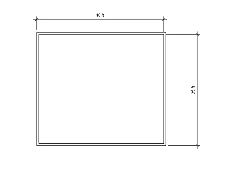
3) From the architecture/ structure toolbar familiarize with options to draw a wall. Create a rectangular layout of walls of about 40’-0” X 35’-0”.
AIM:
To create a rectangular layout of walls of about 40’-0” X 35’-0”.
PROCEDURE:
Open revit software - create new architecture template.
Once the worksheet is opened, click on architecture tab.
Select wall - Place the cursur on sheet to execute walls.
Draw 40' wall on Upper section and bottom section.
After that join 35' wall on parallel to it.
Now an Rectangular wall of 40'X35' is created.
RESULT:
4) From the Annotate toolbar use the aligned option to add dimensions to the layout.
AIM:
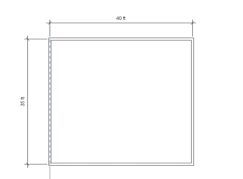
To use aligned option to add dimension from annotate toolbar.
PROCEDURE:
Open revit software - create new architecture template.
Once the worksheet is opened, click on architecture tab.
Select wall - Place the cursur on sheet to execute walls.
Draw 40' wall on Upper section and bottom section.
After that join 35' wall on parallel to it.
Now an Rectangular wall of 40'X35' is created.
Now from annote toolbar - click on aligned dimension.
Place the cursor on required wall and select the side to be dimensioned.
Now Dimensions are created by using Aligned from annotate toolbar.
RESULT:
5) Use the properties browser to switch to different wall types.
AIM:
To use properties browser to switch different wall types.
PROCEDURE:
Open revit software - create new architecture template.
Once the worksheet is opened, click on architecture tab.
Select wall - Place the cursur on sheet to execute walls.
Draw 40' wall on Upper section and bottom section.
After that join 35' wall on parallel to it.
Now an Rectangular wall of 40'X35' is created.
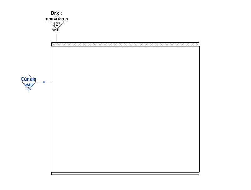
Now select the desired wall to be changed - on left side properties tab displays.
In property tab - select Masonary wall of 12".
Now select another wall - change it to Curtain wall in property tab.
Now desired walls are changed to different wall types by using property tab.
RESULT:
6) Create a 3D view from the view toolbar and save the view with the appropriate name.
AIM:
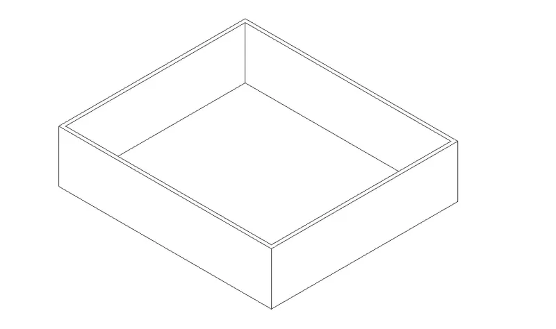
To create a 3D view from view toolbar and save the view.
PROCEDURE:
Click on view toolbar.
Open 3D view.
Click on view template.
Now change the wall properties such as colour, surface, etc.
Then in view dialogue box, name it as 3D view.
Then the view will be created and can be seen.
RESULT:
7) 7) Navigate through the 3D model using the view cube. Orbit/pan through the model layout created.
AIM:
To navigate through the 3D model using the view cube and to Orbit/pan through the model layout created.
PROCEDURE:
Click on view bar and select different views.
To pan - click on navigation tool wheel below the view cube.
Click on left curson to pan or orbit on the mouse.
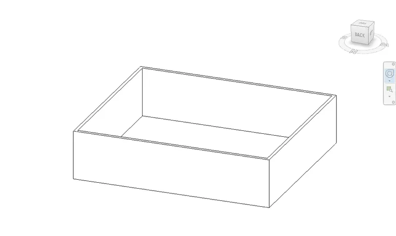
RESULT:
Use of pan or orbit in navigation wheel from view cube is shown.
8) Use the visibility settings option below to switch model to shaded, realistic, hidden lines options.
AIM:
To Use the visibility settings option below to switch model to shaded, realistic, hidden lines options.
PROCEDURE:
At bottom, click on cuboid shape image to change the view.
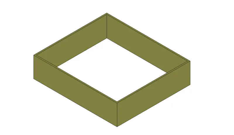
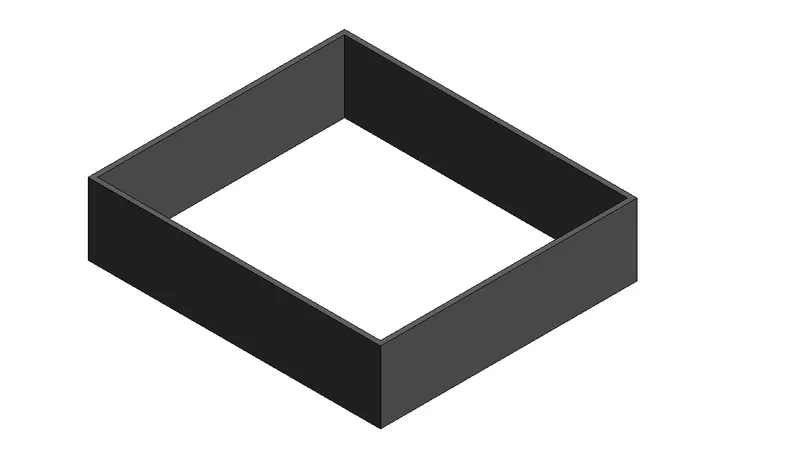
It shows wireframes, shaded, realistic, hidden lines etc.
Select shaded to seen as shown below.
Now select Realistic, as shown below.
Likewise repeat the process for hidden lines.
RESULT:
Shaded, Realistic, and Hidden options are viewed from visibility settings.
9) Turn the sun path on and off to view shadings in the layout created.
AIM:
To turn the sun path on and off to view shadings in the layout created.
PROCEDURE:
Click on the icon of sun from bottom toolbar.
Click on sun path - on.
Now date and time along with sun is visible.
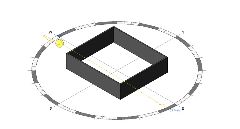
Similarly turn off the sun path.
RESULT:
Use of sun path on/off are made.
10) Use the Manage toolbar to enter project settings, project name, and project issue date (choose according to your convenience).
AIM:
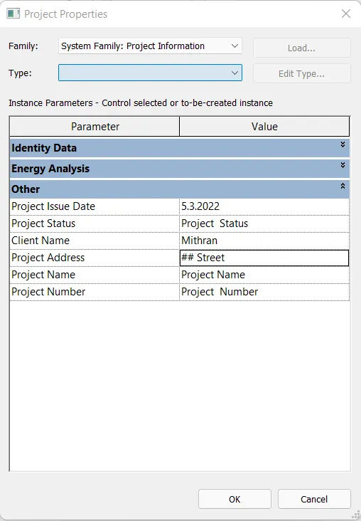
To use the Manage toolbar to enter project settings, project name, and project issue date.
PROCEDURE:
Click on manage toolbar.
Select project information.
Now Project information dialogue box appears.
Now change issue date, Name, Client details as per requirement.
Similarly add address, project name.
RESULT:
11) What is the Analyze toolbar used in Revit? How it is beneficial for design and modeling.
Analyze toolbar helps in evaluting the building performance by analyzing the model such as loads, boundary conditions etc.
It provides sustainability for the project.
- BENIFITS:
It is used largely by structural engineers for following terms:
i. Boundary condition
ii. Load cases
iii. Load combination
It provides energy optimization and energy analysis.
It is also used by MEP engineers for Heat and cool loads analysis.
To creating heating and cooling load analysis report and useful for mechanical engineers in ventilators ducts.
It also allows to acheive the progress of project together in all disciplines.
12) What are the links that Revit supports to be linked to the model?
Links are found under insert tab.
It is used to link different files to parent file.
LINK REVIT - Allows to link another revit model to parent revit file.'
LINK IFC - For additional design works.
LINK CAD - To link 2D cad file to parent revit file.
LINK TOPOGRAPHY - To link current model.
MANAGE LINKS - Manages links to the building models.
13) Why do you need the Collaborate tab in Revit? How it supports modeling and its efficiency.
It has the features to collaborate the team members to execute the work in same parent file.
It helps the team members of different disciplines to work on same project.
Work can be done faster.
It has high efficiency.
We do not have to wait for the file from dislipline to start the project of next discipline.