Introduction to REVIT concepts
1) From the file menu, create a new project (Structural / Architectural / Construction template ) and name the project appropriately
Aim: To create a new project (Structural / Architectural / Construction template ) and give the name to project using Revit software.
Introduction:
- Revit is a Building Information modelling software used by Architects, structural engineer, electrical engineer, mechanical engineers, plumbing engineers.
- In this software we can create the new projects with structural /Architectural /Construction template by naming them as per our choice by using the file menu.
Procedure:
- Open Revit software.
- Double click on the screen, it will open Rivet file menu (home page) as shown below.
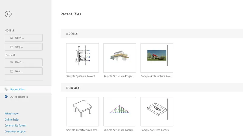
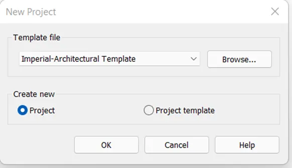
- Select the NEW option from MODELS menu, it will open the new project dialog box.
- From the new project dialog box, select the template file as Imperial-Architectural template file.
- Below that click on project radio baton, and select ok, it will open the Revit window.
- From the Revit window, click on file tab, select the SAVE option from the list.
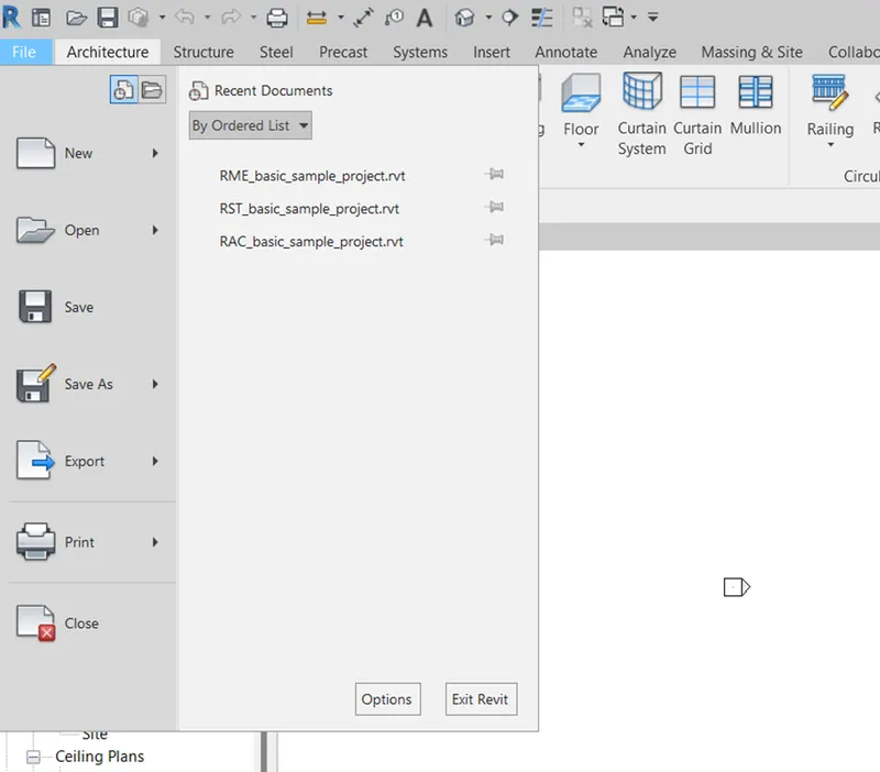
- By selecting the SAVE option, it will open the save as dialog box.
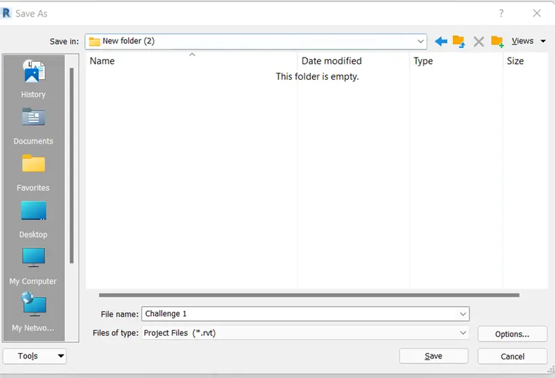
- Select the destination folder, name the file as Challenge 1, and select Save option from dialog box, it will save the file.
Result:
New project naming Challenge 1 is created with the structural template using Revit software by following above mentioned procedure.
2) Save the new project file. Close and open using icons from file toolbar
Aim : To save the new project file, close it and open using icons from file toolbar in Revit Software.
Introduction :
- In BIM software Revit, the new project file can be saved by assigning them desired name by using the file tab.
- We can also close the project file by using the same file tab.
- In Revit software the project file can be opened by using the icons from file toolbar (home page) of Revit software
Procedure :
- In previous question we have saved the project naming Challenge 1.
- For once again saving, click on File option from menu bar and again select the SAVE option from list.
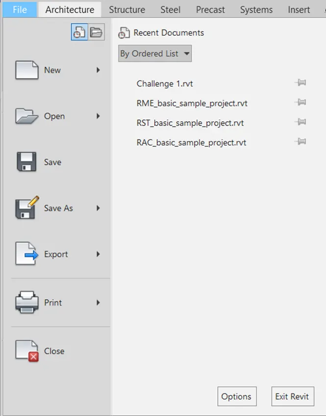
- For closing the file, again select the file menu, click on close option from the list, it will open the home page of Revit.
- From the home page of Revit, select the Challenge 1 naming icon and click on it, it will open the file.
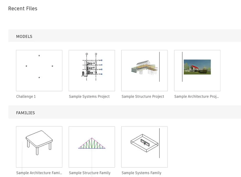
Result:
The new project file naming Challenge 1 is saved, closed and again opened using Revit software by following above mentioned procedure.
3) From the architecture/ structure toolbar familiarize with options to draw a wall. Create a rectangular layout of walls of about 40’-0” X 35’-0”
Aim : To create a rectangular layout of walls of about 40’-0” X 35’-0” using the Revit software.
Introduction :
- Revit is the Building Information Modelling tool which is used by Architect, structural and MEP engineers.
- In the Revit software we can create the layout of wall using the architectural or structural toolbar by using the draw panel.
Procedure:
- open the Revit software.
- Double click on the screen to open the homepage of Revit software.
- Click on the icon naming Challenge 1 from file toolbar, it will open the project file naming challenge 1.
- From the Architecture tab, select the Wall icon from build panel, it will open the modify wall tab.
- From modify wall tab, from draw panel select the line icon.
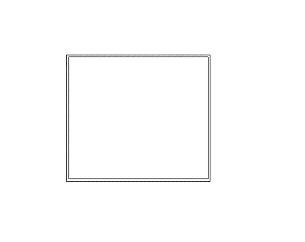
- Click to enter the wall start point, move the cursor in horizontal direction and specify length as 40’ and press enter.
- Move the cursor vertically downward and type 35’ and press enter.
- Again, move the cursor horizontally in left direction and specify length as 40’ and press enter.
- Move the cursor in vertically upward direction and select the endpoint as start point of first wall to close the geometry and press escape twice.
- Click on the Save icon from top toolbar to save the modifications made in project file naming Challenge 1.
Result:
The rectangular layout of wall is created in Revit software by following above mentioned procedure as shown below.
4) From the Annotate toolbar use the aligned option to add dimensions to the layout
Aim : To add dimensions to the layout by using the aligned option from Annotate toolbar in Revit software.
Introduction :
- In BIM software Revit we can add dimensions to the layout using the Annotate toolbar.
- From the Annotate tab, from dimensions panel we can use the linear option to give dimensions to the liner lines and Aligned option to give dimensions to the inclined lines.
- As the layout is having the walls with the inclination 0 and 90 degrees we can use the linear as well as aligned option from annotate tab.
Procedure :
- Open the Revit software double click on screen to open homepage of Revit software.
- From the file menu select the project naming Challenge 1 as saved in previous question procedure and click on it to open the file.
- From the toolbar click on the Annotate tab.
- From the Annotate tab select the Aligned option from dimension panel.
- From the modify toolbar select the wall face option.
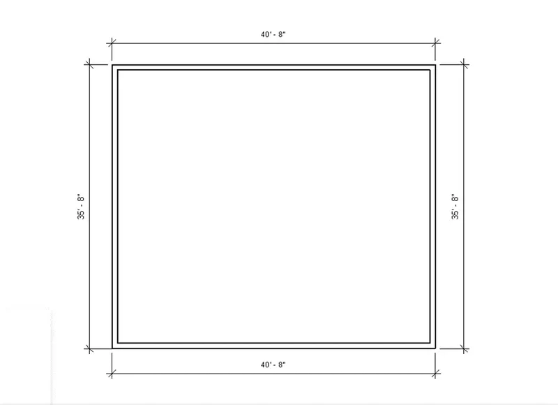
- Click on the starting face of the wall followed by clicking on opposite face of the wall and to give dimensions to the horizontal wall at desired location by moving cursor at appropriate position and click on it.
- Similarly give the dimensions to other vertical and horizontal faces of the wall. By following the same procedure.
- Click on the Save icon from top toolbar to save the modifications made in project file naming Challenge 1.
Result: using the aligned option the dimensions are added to the layout as shown below.
5) Use the properties browser to switch to different wall types
Aim : To change the walls to different types using properties browser in Revit software.
Introduction :
- property browser in Revit software shows the graphics, underlay, extent, identify data, phasing properties.
- by using the property browser we can change the properties of drawn units.
- Similarly by using the properties browser we can change the type of wall.
Procedure :
- Open the Revit software double click on screen to open homepage of Revit software.
- From the file menu select the project naming Challenge 1 as saved in previous question procedure and click on it to open the file.
- Make sure property browser window is open, if not then type PP to open it.
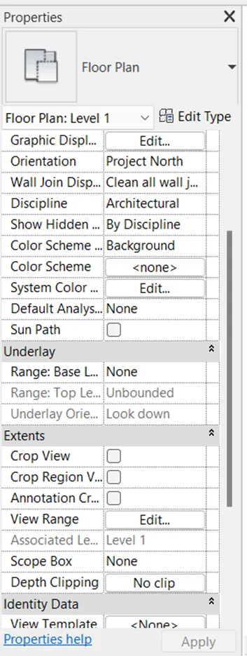
- Click on top horizontal wall to switch to other wall type.
- From the property browser palettes click on wall type and select the basic wall type as Generic – 12”.
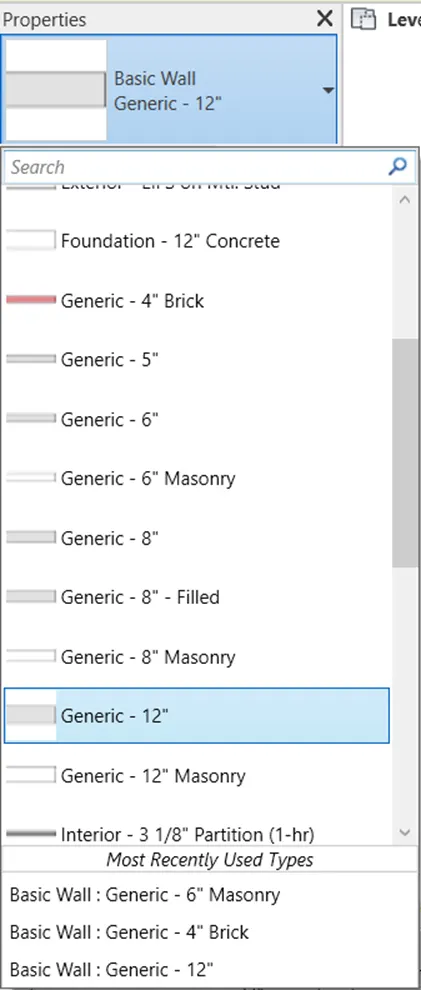
- Similarly select the second wall and change the wall type as Generic – 4”.
- Select the third wall and change the wall type as Generic – 6”.
- Click on the Save icon from top toolbar to save the modifications made in project file naming Challenge 1.
Result :
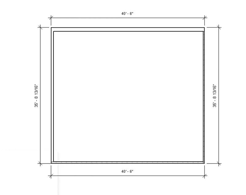
Therefore, by using the property browser the wall type is switched to different wall type in Revit software as shown below.
6) Create a 3D view from the view toolbar and save the view with the appropriate name
Aim : To create a 3D view from the view toolbar and save it with appropriate name in Revit software.
Introduction :
- 3D view option from the view tab in Revit software is used to change the view to 3D view.
- In Revit we can save different views using view cube.
- View cube is used to navigate the 3D views.
- It is shown in a corner of the drawing area. over the model, in an inactive state.
- When we position the cursor over the View Cube, it becomes active.
- By right clicking on the corner of view cube we can save the view with the desired name.
Procedure :
- Open the Revit software double click on screen to open homepage of Revit software.
- From the file menu select the project naming Challenge 1 as saved in previous question procedure and click on it to open the file.
- Click on the View tab from toolbar in the Revit software.
- Select the 3D view icon from the create panel of the view tab.
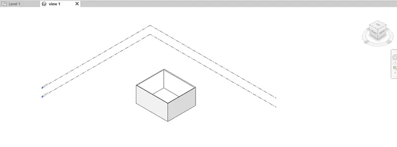
- In 3D view icon, select the Default 3D view option, it will display the 3D view of layout of the wall on the screen as shown below.
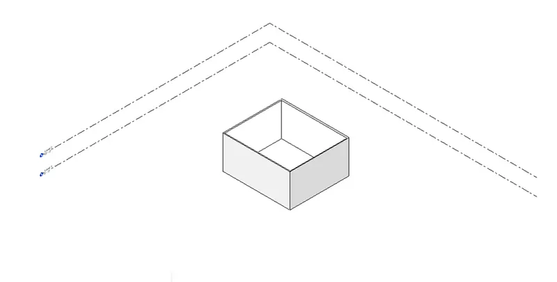
- To save the view, move the cursor on the view cube and right click on it.
- Select the save view option it will open the dialog box to name the view as shown below.
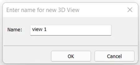
- Type the view name as view 1 and select ok to save the view.
Result :
Therefore, 3D view of layout is created and saved by the name view 1 using view toolbar in the Revit software.
7) Navigate through the 3D model using the view cube. Orbit/pan through the model layout created
Aim : To navigate through the 3D model using the view cube, orbit and pan through the created model layout.
Introduction :
- we can navigate through the 3D model using view cube and navigation bar.
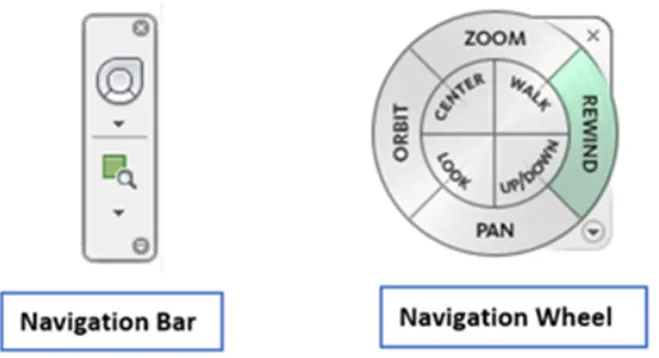
- When we click on top icon of navigation bar it will open the navigation wheel.
- Navigation wheel contains orbit, zoom, pan and rewind option through which we can navigate the various views of the model.
Procedure :
- Open the Revit software double click on screen to open homepage of Revit software.
- From the file menu select the project naming Challenge 1 as saved in previous question procedure and click on it to open the file.
- The screen will display the output obtained in the previous question.
- Make sure navigation bar is displayed on the top right corner of workspace.
- If navigation bar is hidden to make it visible, click on the view tab on the toolbar.
- In that select the user interface dropdown from the windows panel, select the navigation bar option it will display the navigation bar.
- Click on the first icon of the navigation bar, it will open the navigation wheel as shown below.
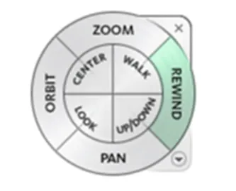
- To orbit through the layout select the ORBIT option and orbit the layout using the mouse with pivot.
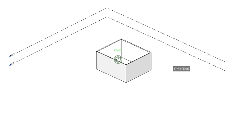
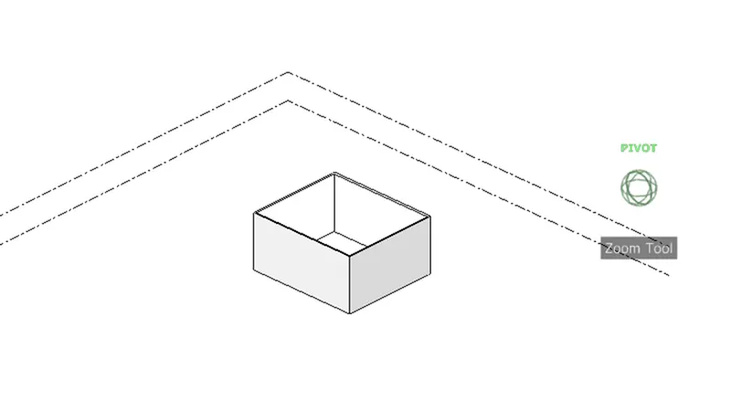
- To zoom in and out through layout select the zoom option.
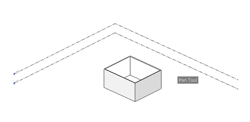
- To pan the view select the PAN option and pan the view using the mouse as shown below.
- Click on the Save icon from top toolbar to save the modifications made in project file naming Challenge 1.
Result:
Navigation through the 3D model using the view cube, orbit and pan is created in the Revit software using above mentioned procedure.
8) Use the visibility settings option below to switch model to shaded, realistic, hidden lines options
Aim : To switch the model to shaded, realistic, hidden lines using the visibility setting in the Revit software.
Introduction :
- In Revit software you can specify different graphic styles for a project view.
- We can switch the model to different visual style by using visibility setting option located at bottom toolbar.
Procedure :
- Open the Revit software double click on screen to open homepage of Revit software.
- From the file menu select the project naming Challenge 1 as saved in previous question procedure and click on it to open the file.
- The screen will display the output obtained in the previous question.
- Click on the visibility setting option from the bottom toolbar as shown below.
- It will display the dialog box to select the desired visual style as shown below.
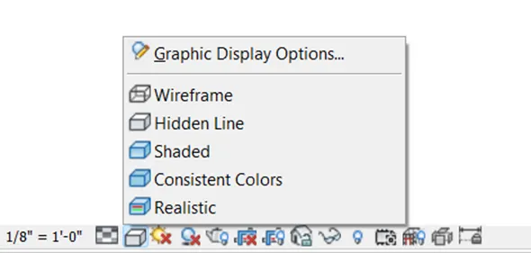
- Select the wireframe option from the list, it will display the wireframe view is as shown below.
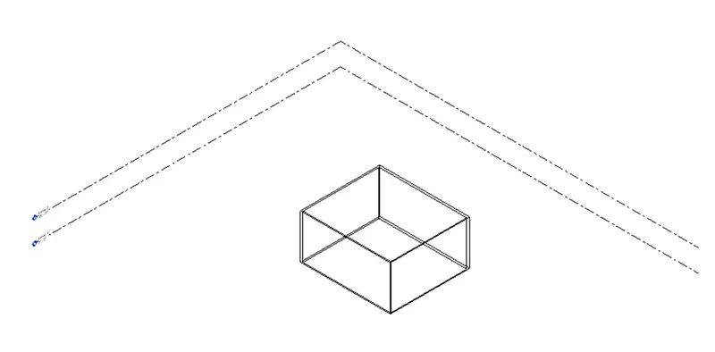
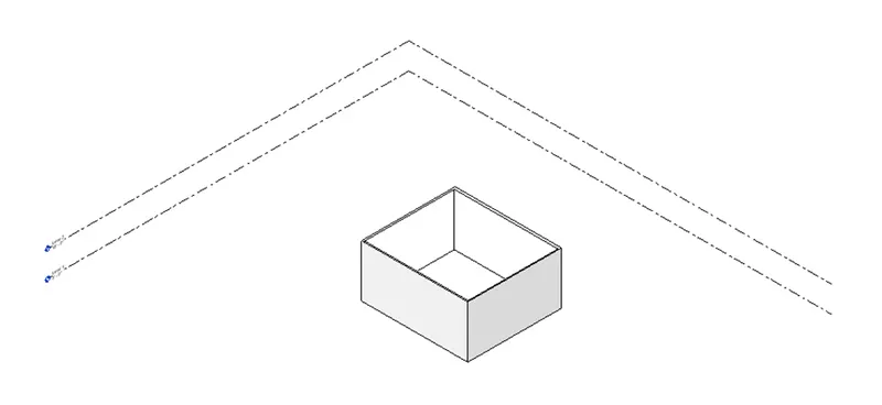
- Now, to switch to the hidden view select the hidden option from the list. The hidden view of the layout is shown below.
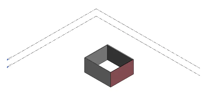
- now, to switch to the shaded view select the shaded option from the list. The shaded view of the layout is shown below.
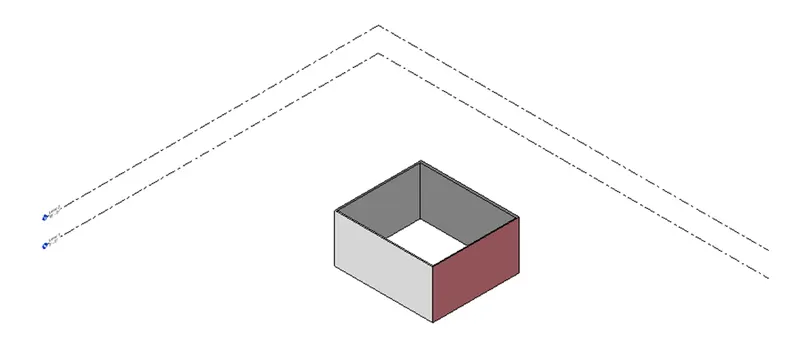
- Now, to switch to the consistent color view select the consistent color option from the list. The view of the layout is shown below
- Now, to switch to the realistic view select the realistic option from the list. The view of the layout is shown below
Result :
The Shaded, realistic and hidden line view is created by using visibility setting option by following the above mentioned procedure in Revit software.
9) Turn the sun path on and off to view shadings in the layout created
Aim : To turn the sun path on and off to view shadings in the layout created in the Revit software.
Introduction :
- By using the sun path on and off setting we can create the shadings to the created layout.
- Sun path on/ of setting icon is located at the bottom toolbar in the Revit software.
Procedure :
- Open the Revit software double click on screen to open homepage of Revit software.
- From the file menu select the project naming Challenge 1 as saved in previous question procedure and click on it to open the file.
- The screen will display the output obtained in the previous question.
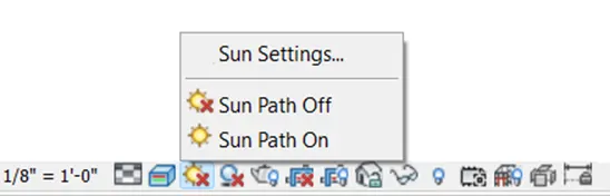
- To turn the sun path on click on the Sun icon from the bottom toolbar, it will open the sun setting option dialog box, click on sun setting option as shown below.
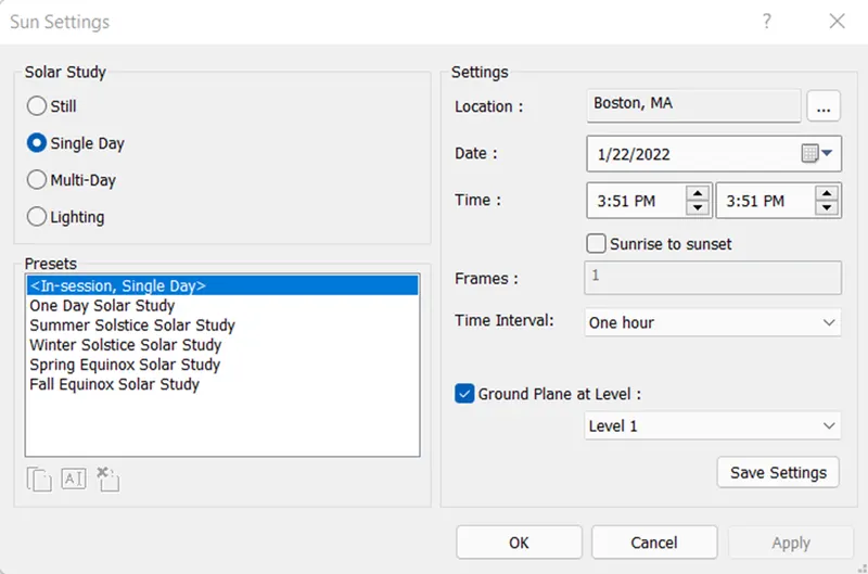
- After clicking on the sun setting option it will open the sun setting dialog box.
- Select the solar study as Single Day.
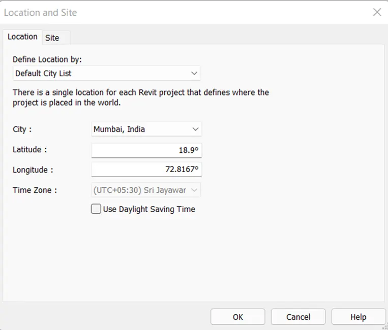
- Click on the list icon of the location it will open the location and site dialog box.
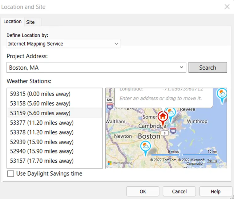
- In location and site dialog box, select the define location by Default city list option.
- Select the city as Mumbai, India from the city list to set the location as shown below and select ok and ok.
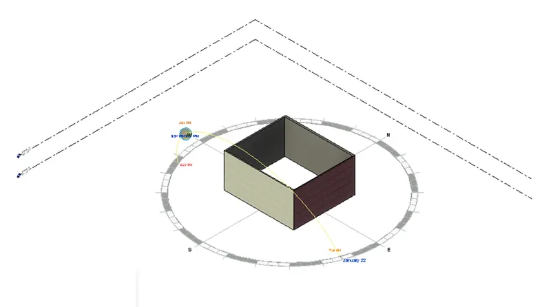
- Again, click on the sun path setting icon from bottom toolbar and turn on the sun path on.
- Similarly click on the sun path setting icon to turn off the sun path.

Result :
The sun path is turned on and off in the Revit software using the above mentioned software.
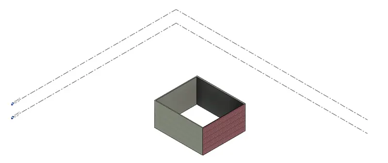
The view with sun path setting on is shown below.
10) Use the Manage toolbar to enter project settings, project name, and project issue date (choose according to your convenience).
Aim : To use the manage toolbar to enter project setting, project name and project issue date in Revit software.
Introduction :
In the Revit software we can set the project setting such as project name, client name, name of organization, client name, address of project, project issue date, status of the project etc by using the project information tool of the manage tab.
Procedure :
- Open the Revit software double click on screen to open homepage of Revit software.
- From the file menu select the project naming Challenge 1 as saved in previous question procedure and click on it to open the file.
- The screen will display the output obtained in the previous question.
- Click on the Manage tab, in that click on the Project information icon from the setting panel, it will open the project information dialog box.
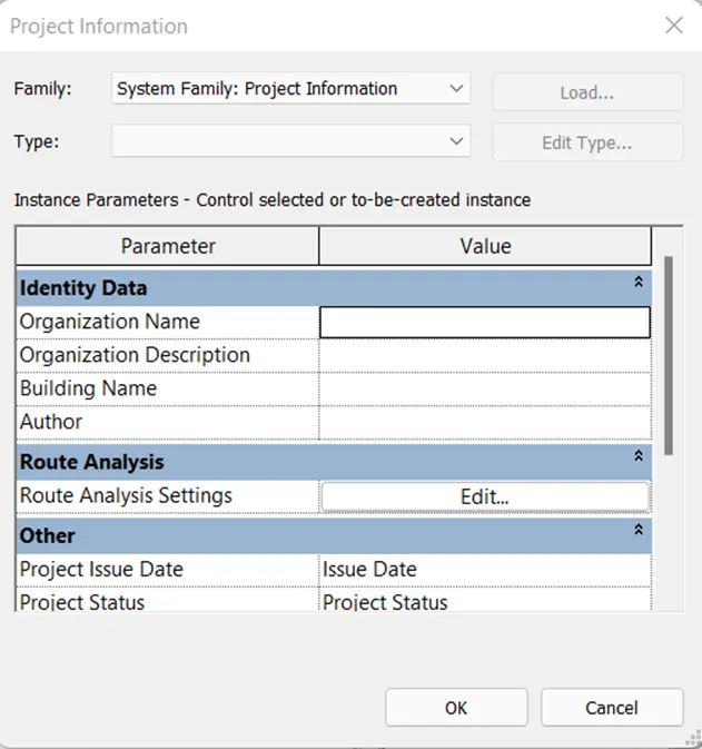
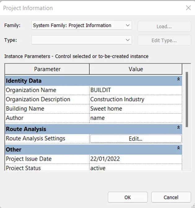
- Type the organization name as BUILDIT, type organization description Construction industry, building name as Sweet home, Author as name.
- Also mention the other information such as project issue date as 20/01/2022, project status as active, project name as residential, project no as 001etc in the dialog box, and select ok.
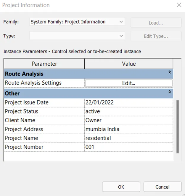
- For selecting the project address click on the 3 dot of project address cell and type the address and select ok.
Result :
Therefore, manage toolbar is used to enter the project setting in Revit software by using above mentioned procedure as shown below.
11) What is the Analyze toolbar used in Revit? How it is beneficial for design and modeling.
Aim : To describe the use and benefits of Analyze toolbar in the Revit for design and modelling.
Introduction :
Revit is BIM software using which one can analyze the various structural parameters associated with the building such as loads coming on the buildings along with various load combinations, energy optimization, structural analysis of the building etc., using the Analyze tab of the Revit software.
Procedure :
- Analyze toolbar in the Revit software contains following panels,
- Analytical model
- Analytical model tools
- Spaces and zones
- Reports and schedules
- Check system
- Color fill
- Energy optimization
- Route analysis
- Structural analysis

- Boundary condition defines point, line and area boundary conditions of the analytical model.
- Loads option from analytical model panel is used to apply point, line and area loads on the model.
- Load cases option used to edit, and add load cases for the analytical model.
- Load combinations add and edit load combinations for analytical model which includes defining name, state, formula and type.
- In energy optimization panel is used to create the energy model and asses the energy and environmental performance of the structure.
Benefits for design and modelling
- Analysis tool is beneficial for design and modelling in the way of structural analysis and energy optimization of the structure.
- Using this tool we can asses the energy and environmental performance of the structure to analyze the sustainability of structure.
- The analyze tab is also used to apply various loads and load combinations coming on the structural model.
- It also provides the option to check the various systems such as electrical circuit, mechanical piping systems etc.
- We can also perform heating and cooling analysis in the energy analysis.
Result :
The uses and benefits of the analysis toolbar in the Revit software are described above.
12) What are the links that Revit supports to be linked to the model?
Aim : To describe the various links that Revit supports to be linked to the model.
Introduction:
various links that Revit support are
- link Revit
- link IFC
- link CAD
- link Topography
- DWF Markup
- Decal
- Point cloud
- Coordination model
- Link pdf
- Link image
Procedure :
One can asses to various links available in Revit software by clicking on the insert tab of the toolbar in the Revit software.
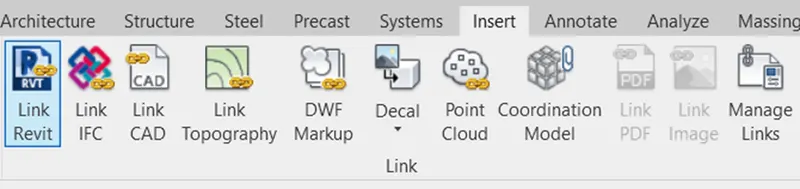
Various links in Revit software are
- Link Revit:
- It is used to link the another Revit model to the current model.
- For example, one can link models together to specify the relative locations of individual buildings on a campus, or to coordinate efforts across disciplines such as architectural, structural and engineering disciplines.
- Link IFC
- Links an IFC file to the current project to reference its information for additional design work.
- If make the changes to the original IFC file and reload the link, the project updates to reflect the IFC file changes.
- Link CAD
- Links a CAD file to the current Revit project.
- Linking is similar to xref in AutoCAD , when original linked file changes these changes are reflected in the file when we reload the project.
- Link Topography
- Link existing topography to the current Revit model.
- DWF Markup
- Links marked- up DWF file into a Revit project so that we can markup on corresponding sheets.
- Point cloud
- Links a point Cloud file (*.rcp or *.rcs) into current project.
- The Point Cloud tool can also be used to index a raw format point cloud file for use in a project.
- When linked into a project, point clouds can provide references when placing or editing model elements.
- Coordinate model
- Links a NWD or NWC file to provide context for the Revit model.
- This feature allows you to compare the Revit model to a non-Revit model for coordinate purposes.
- Link PDF
- Insert a link to a PDF into a model view.
- We can only link PDFs in 2D views, we can not link PDF in a 3D views.
- Link image
- Insert a link to an image a model view.
Result:
The links that Revit supports to be linked to the model are described in the above procedure.
13) Why do you need the Collaborate tab in Revit? How it supports modeling and its efficiency.
Aim : To describe the need of the Collaborate tab in the Revit and support and efficiency in the modelling.
Introduction :
Collaborate tab in the Revit contains following panels
- Communicate
- Manage collaboration
- Synchronize
- Manage models
- Coordinates
- Share
Procedure :
Revit provides several different ways to collaborate with team members who are also using the software.
- You can link multiple Revitmodels together, allowing team members to work in context.
- Through worksharing, users on the same local area network (LAN) can work together in the same Revit
- When collaboration needs to occur among users who are not in the same geographic location, use Revit Server or Revit Cloud Worksharing.
- Revit Server connects offices who share a network but are not in the same geographic location.
- Revit Cloud Worksharingis a cloud-based service that allows any Revit users inside or outside a network to collaborate on a Revit

- Collaborate tool in collaborate tab enables collaboration so team members can work on a model simultaneously.
- Synchronize and modify tool from collaborate tab allows us to specify options for synchronization operation.
- Reload latest tool loads the updates from central model to local copy of the project.
- Worksharing monitor launches worksharing monitor to manage a file based workshared model.
- Restore backup tool rolls back changes made to a workshared project or saves a selected backup versions to be the current working model.
- Manage cloud model tool manage Revit models in the cloud.
- Publish setting selects the views and sheets to publish to the cloud.
- Copy/ monitor tool monitors and coordinates changes to elements that affect team from different disciplines.
- Coordinate review tool displays warnings about project changes that may affect team from different disciplines.
- Interference check runs an interference check report or shows the most recent report.
- Shared view opens and closes the shared view palettes.
Result :
Thus, need of collaborate tab in Revit and its supports to modelling and its efficiency is described in the above procedure.