Introduction to REVIT concepts
Q1. From the file menu, create a new project (Structural / Architectural / Construction template ) and name the project appropriately
Ans:
AIM : To create a new project using the file menu and name the project appropriately
PROCEDURE :
STEP 1 : Open Revit Software
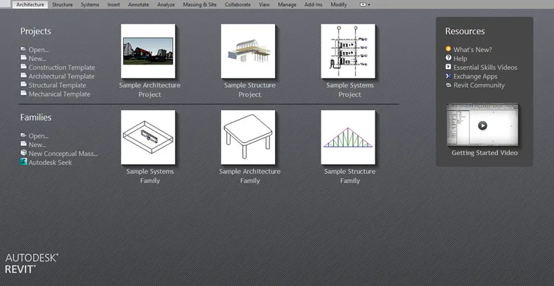
STEP 2 : Click on new and select the template
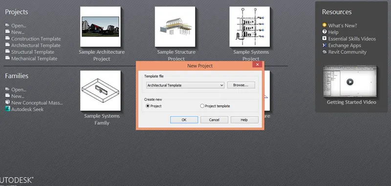
STEP 3 : Click on Architectural template and press ok
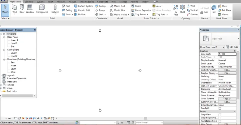
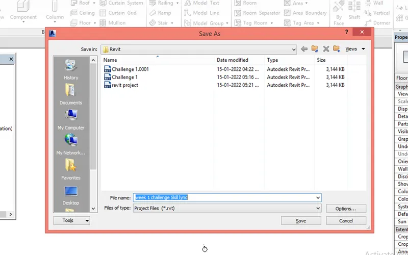
STEP 4 : Click on save icon or click on the revit software logo 
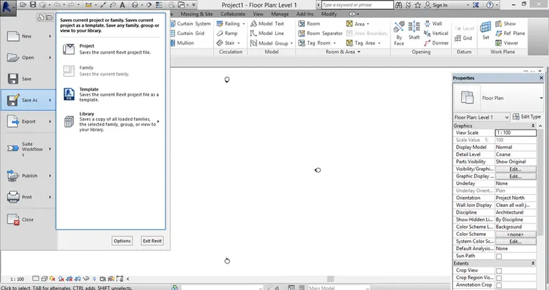
STEP 5 : Save the file giving the path to the file
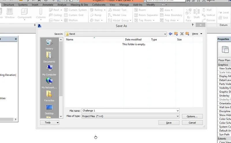
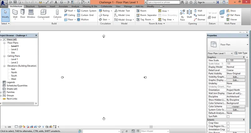
RESULT :
Q2. Save the new project file. Close and open using icons from file toolbar
Ans :
AIM : To save the file and close and open using icon from file bar
PROCEDURE :
STEP 1 : Open Revit Software
STEP 2 : Click on new and select the template
STEP 3 : Click on Architectural template and press ok
STEP 4 : Click on save icon or click on the revit software logo
STEP 5 : Save the file giving the path to the file
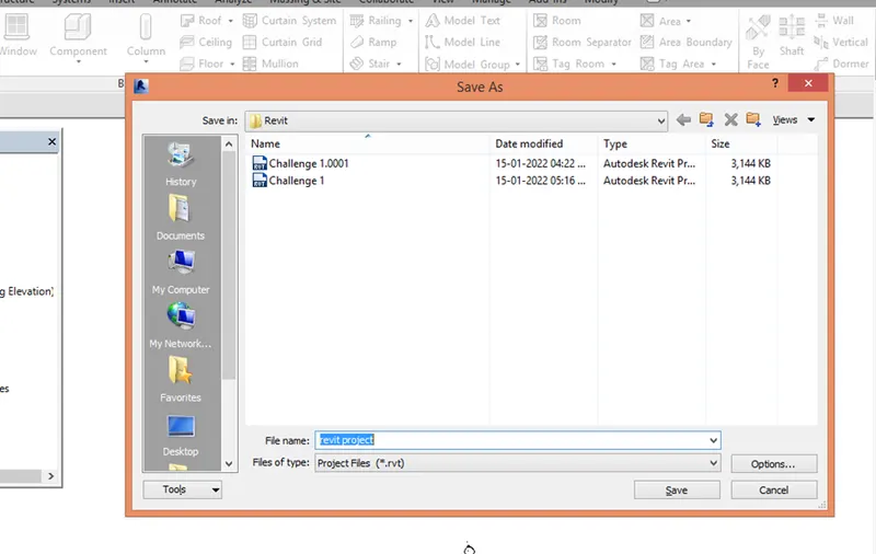
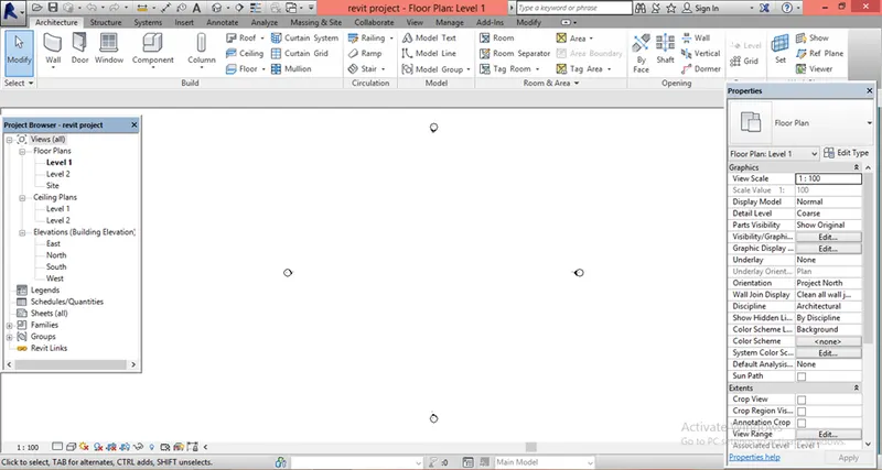
STEP 6 : Open Revit software
Go to the file tab and then click open and select the file which needs to be open
And close the file using file tab by clicking on exit revit
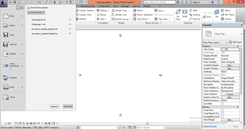
RESULT :
Q3.From the architecture/ structure toolbar familiarize with options to draw a wall. Create a rectangular layout of walls of about 40’-0” X 35’-0”
Ans :
AIM : To create a rectangular layout of walls of 40’-0”x35’-0”
PROCEDURE :
STEP 1 : Open Revit Software
STEP 2 : Click on new and select the template
STEP 3 : Click on Architectural template and press ok
STEP 4 : Click on save icon or click on the revit software logo
STEP 5 : Save the file giving the path to the file
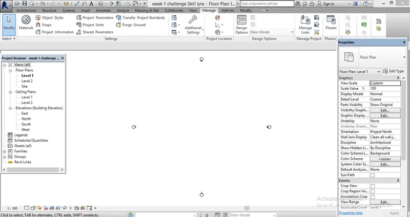
STEP 6 : From Architectural tool bar click on the wall icon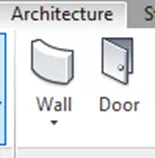
Using wall icon draw the rectangular layout of wall
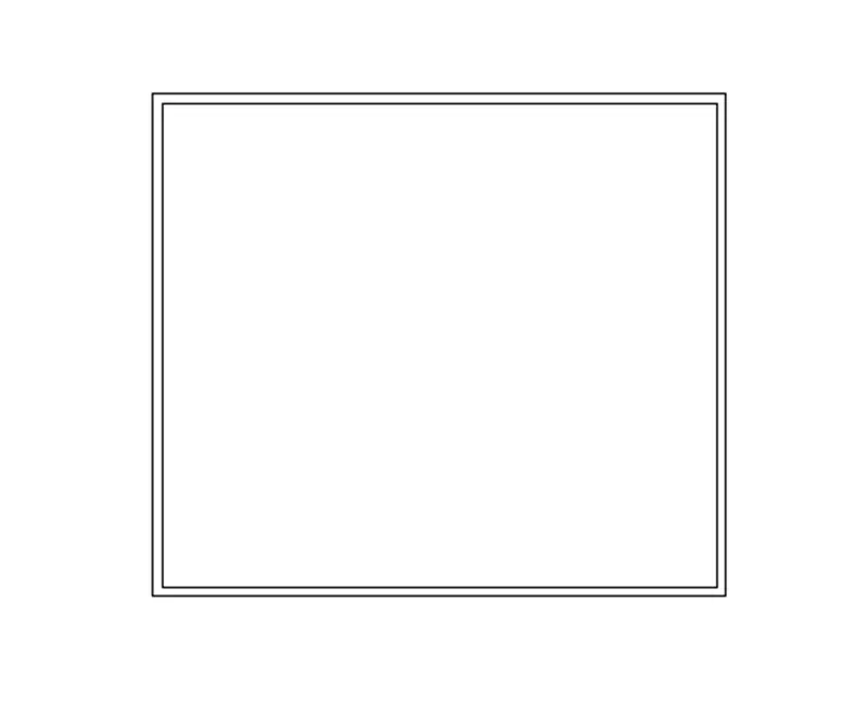
RESULT : Wall is by created using wall icon in architectural tool bar
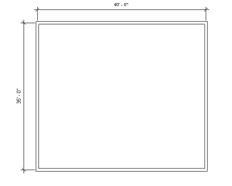
Q4. From the Annotate toolbar use the aligned option to add dimensions to the layout
Ans :
AIM : To add dimensions to the layout
PROCEDURE :
Click on the annotate tool bar and select aligned dimensions and give dimensions to the layout.
RESULT : Dimension is added to the model by using aligned dimensions
Q5. Use the properties browser to switch to different wall types
Ans :
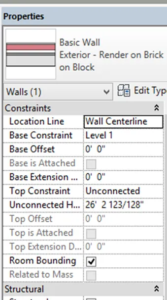
AIM : Use the properties browser to switch to different wall types
PROCEDURE :
STEP 1 : Create a wall using the wall icon in architectural tool bar
Select the wall and go to properties and change the wall type
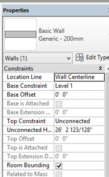
RESULT : By using properties browser change the type of the wall
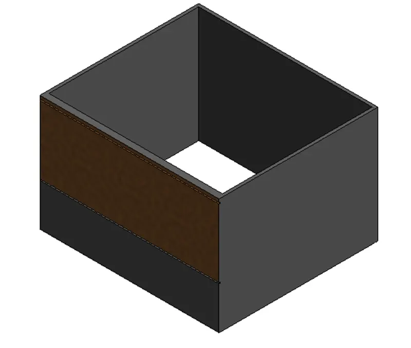
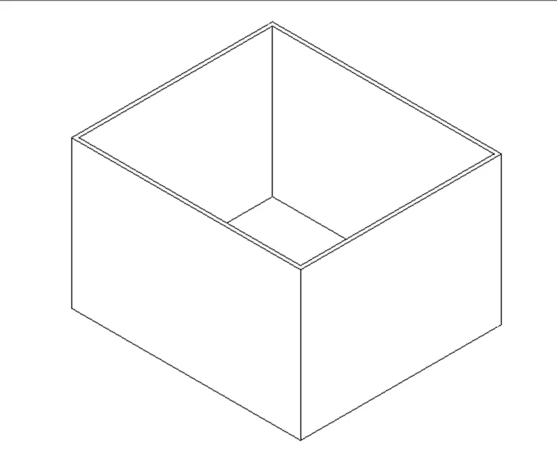
Q6. Create a 3D view from the view toolbar and save the view with the appropriate name
Ans :
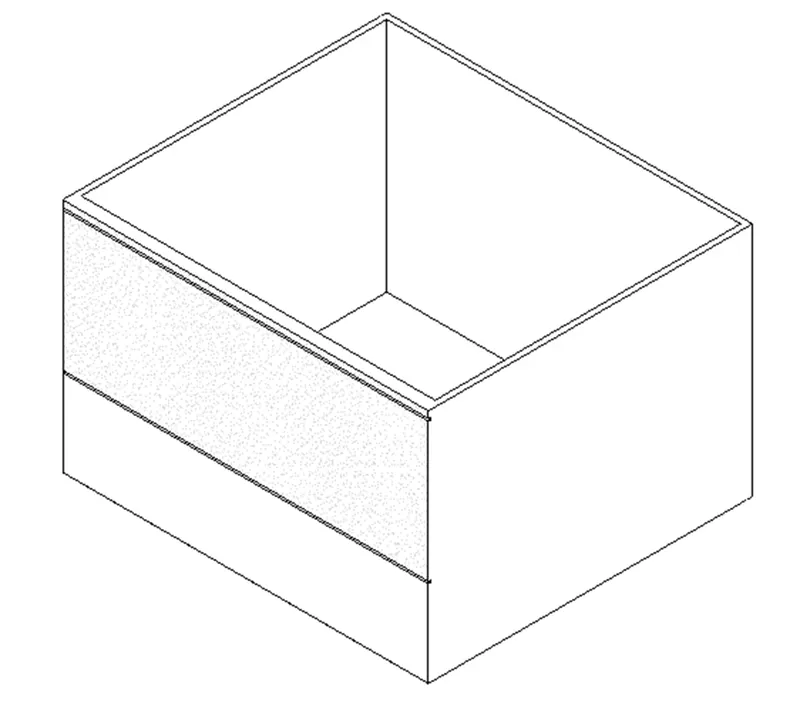
AIM : To create view tab from the view tool bar and to save it
PROCEDURE :
STEP 1 : Go to view tab and click on 3D view
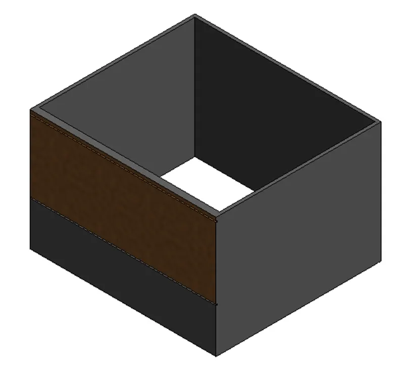
STEP 2 : Click on the property palate and select the 3D view name and now rename the view name as required
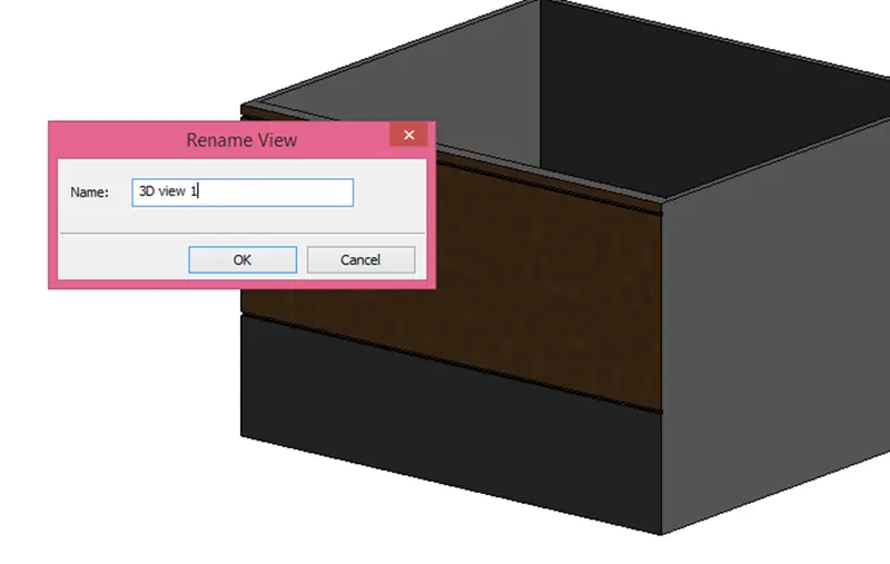
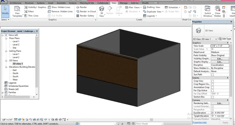
RESULT : 3D view is created successfully and view name has been changed to 3D view 1
Q7. Navigate through the 3D model using the view cube. Orbit/pan through the model layout created
Ans :
AIM : To navigate the 3D plane using orbit/pan
PROCEDURE :
Click on the panel or view port to change the views 
RESULT : By clicking the navigate bar we can change the 3D view
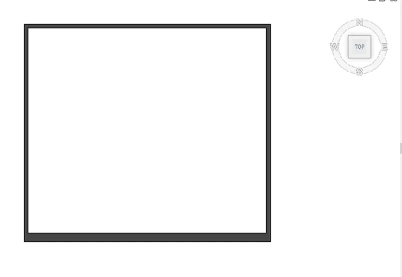
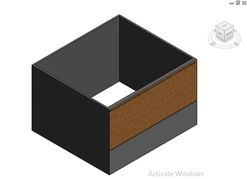
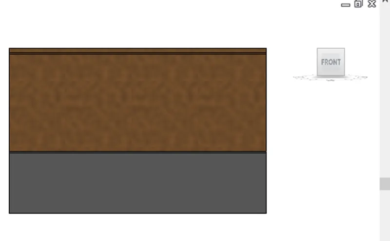
Q8. Use the visibility settings option below to switch model to shaded, realistic, hidden lines options
Ans :
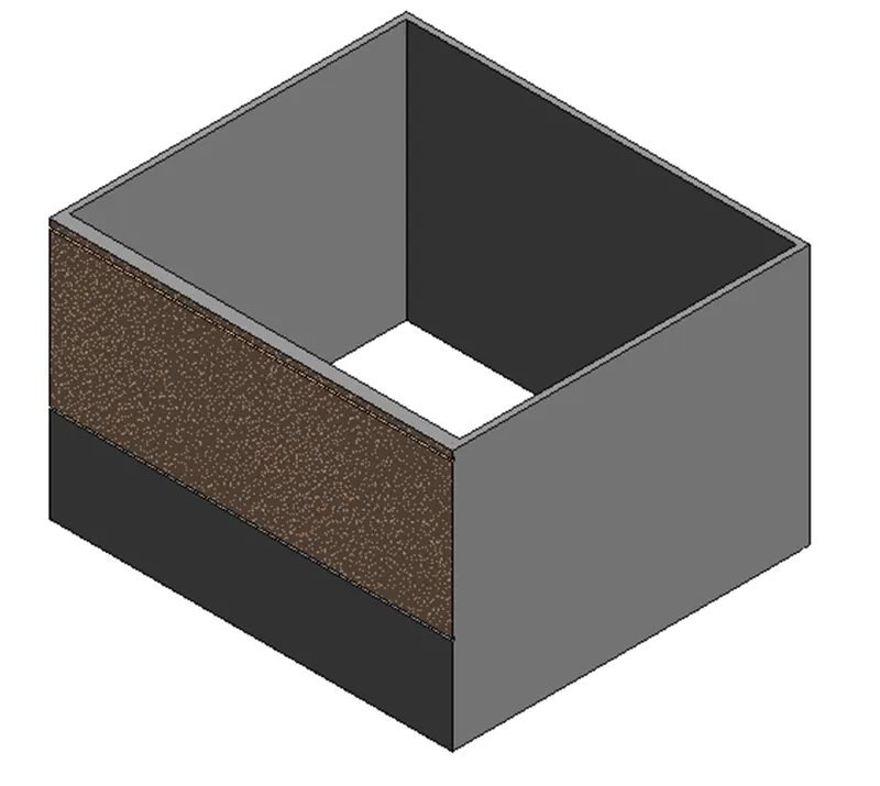
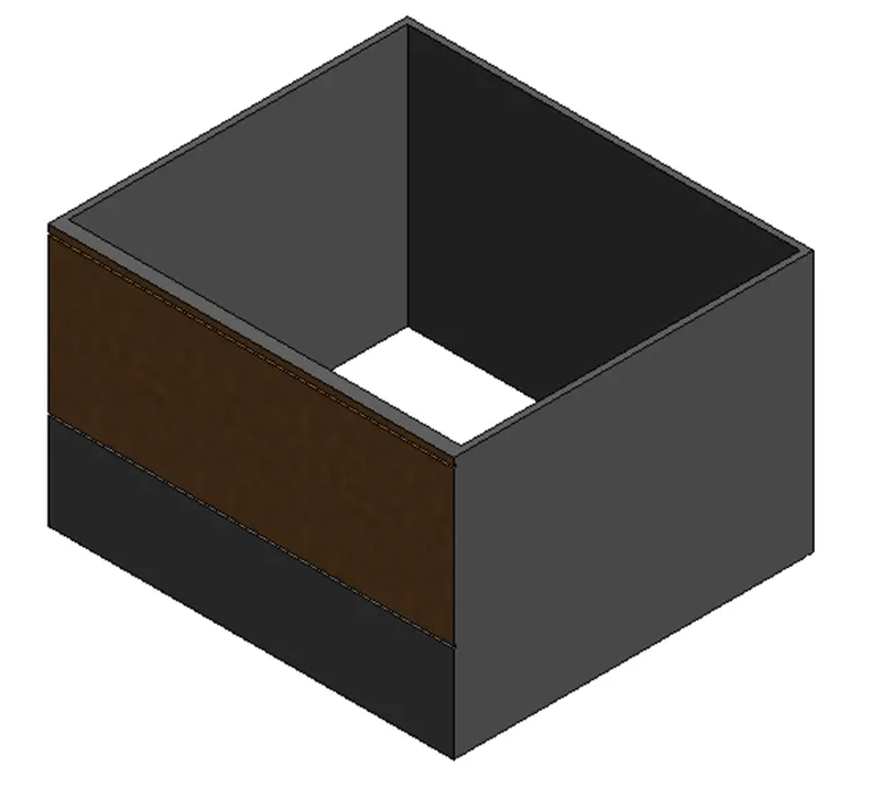
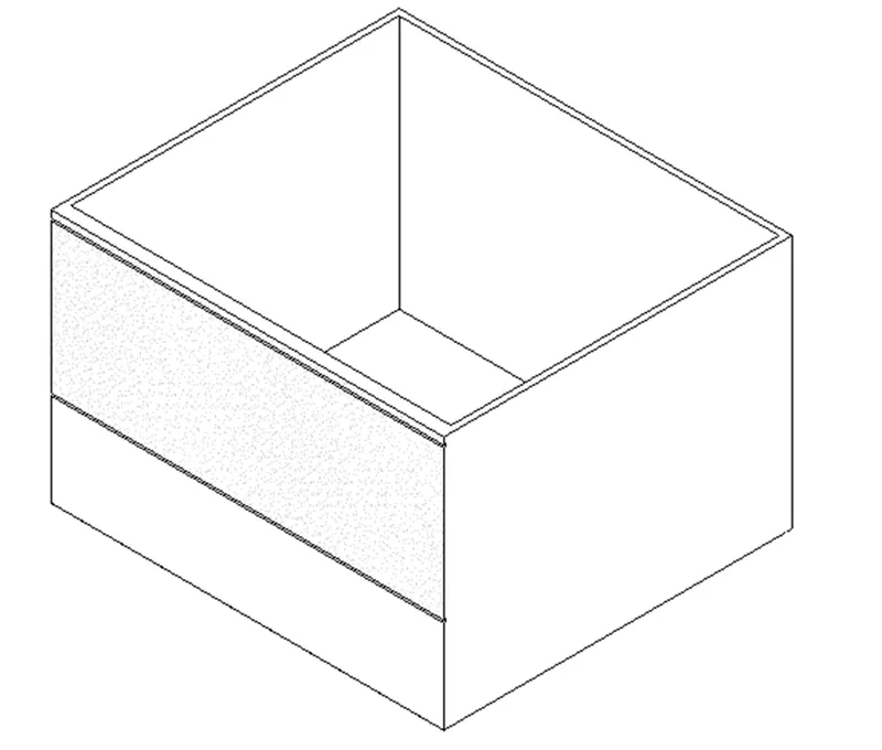
AIM : To use the visibility setting option below to switch model to shaded, realistic, hidden lines options.
PROCEDURE :
Click on the visibility section which is in below tab 
RESULT :
Change the view to shaded
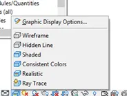
Change the view to realistic
Change the view to hidden
Q9. Turn the sun path on and off to view shadings in the layout created
Ans :
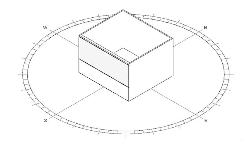
AIM : To turn the sunlight on and off to view shadings in the layout created
PROCEDURE :
Click on sunlight on and off which is in the below bar 
RESULT :
Sunlight on
Sunlight off
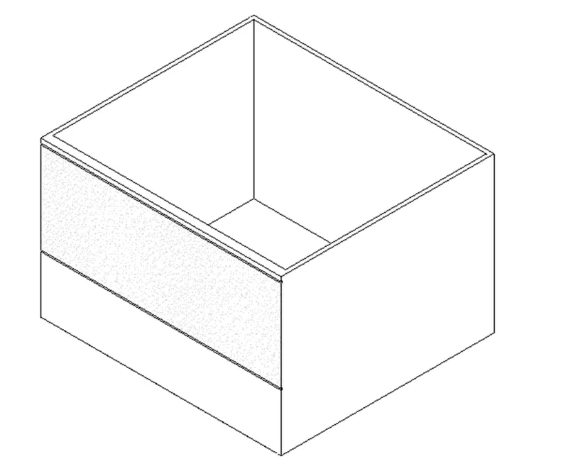
Q10. Use the Manage toolbar to enter project settings, project name, and project issue date (choose according to your convenience).
Ans :
AIM : To use the manage tool bar to enter project settings, project name and project issue date
PROCEDURE :
Click on manage tool and select project information
RESULT : In the project information change the details according to the project
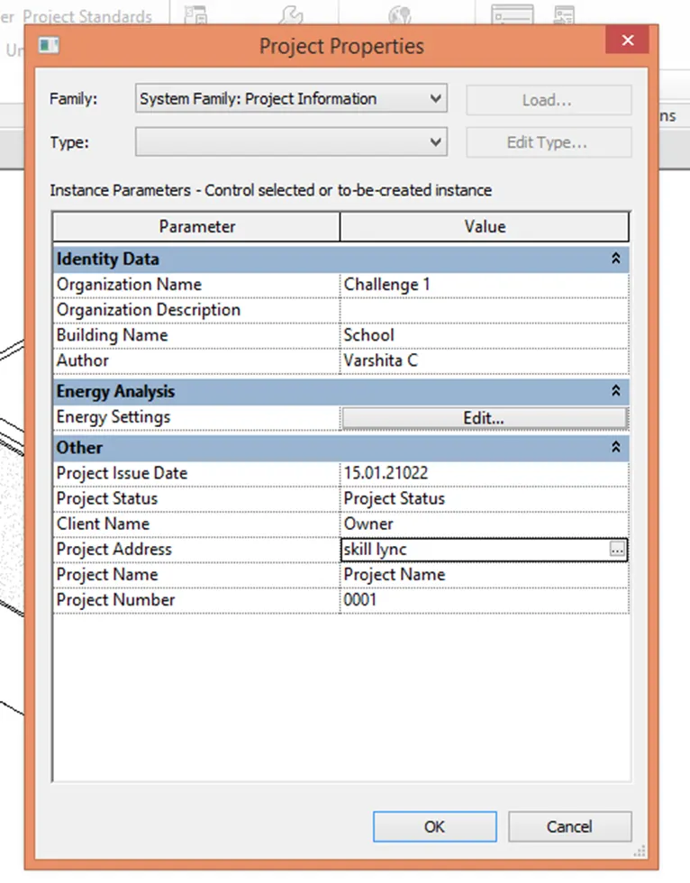
Q11. What is the Analyze toolbar used in Revit? How it is beneficial for design and modeling
Ans:

Analyse toolbar helps you to perform analysis on our structural building. The boundary conditions enable you to define point line and area boundary conditions in an analytical model. It will verify the boundary condition family types are located and assigned in your parametric features of the structural model. Similarly we can apply point load at a model to evaluate the performance of the buildings. Similarly we can add and edit load cases to define the design standard suggested load case to a model, we can combine different load cases using load combination icon. It will be enable to add and edit load combinations for the analytical model
Q12. What are the links that Revit supports to be linked to the model?
Ans :

Links that support Revit
- Link Revit : This allows to link another revit model to the current model.
- Link IFC : To link IFC file to current revit model to reference to its information for additional design work.
- Link CAD : To link the 2D CAD file to current revit file to create 3D by revit tool.
- Manage links : Provides feature to manage the links to the building models.
- Link image : It allows us to link an image for the progressing revit model.
- Link PDF : It allows us to link the PDF file to the current project.
- Link Topography : It links the existing topography to the present revit model.
Q13. Why do you need the Collaborate tab in Revit? How it supports modeling and its efficiency
Ans :
Collaborate tab can be used to access the same project file with all the members in the team and changes can be made by everyone. It improves the efficiency because multiple users in a team can work on same project at a time and alk the inputs given by different users will be updated to everyone.