Introduction to REVIT concepts
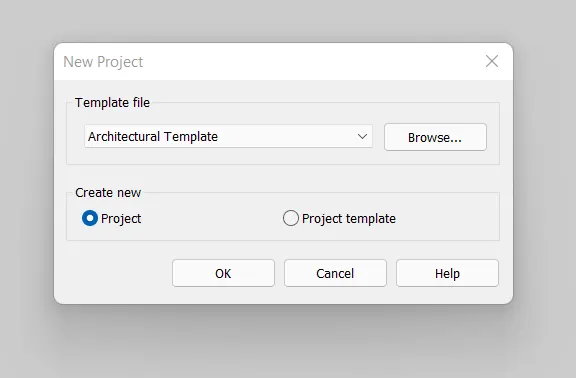
1) From the file menu, create a new project (Structural / Architectural / Construction template ) and name the project appropriately.
STEPWISE PROCEDURE:
- Open the Revit software and wait for it to load.
- Go to the "File" tab and click on "New".
- After choosing the new option, click on the new project menu.
- A new project dialogue box will pop up with various settings to be made.
- Select the drawing template as an Architectural template from the first drop-down list.
- Click on the project radio button and then proceed by hitting ok.
- And that's it, you have a new Architectural project opened up on the screen.
2) Save the new project file. Close and open using icons from the file toolbar.
STEPWISE PROCEDURE:
- When you have the new project opened on the screen, you have more than one ways to save it.
- One way is to click on the File tab and then click on the save button and then specify the save location.
- And the other way is to press "Ctrl+S" on the keyboard.
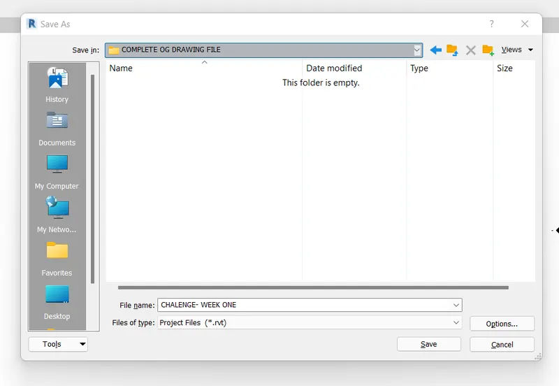
- A save dialogue box will open up, select the file location on your local computer.
- After selecting the location of the save folder, you can select the file format to be chosen.
- And after confirming the file-related settings, you can then click on the save option within the dialogue box.
- This will save your project in the standard ".rvt" format.
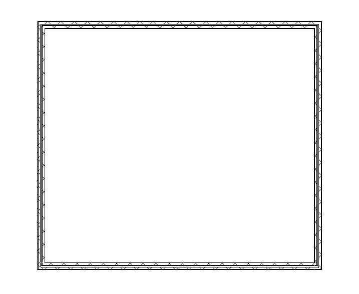
3) From the architecture/ structure toolbar familiarize with options to draw a wall. Create a rectangular layout of walls of about 40’-0” X 35’-0”
STEPWISE PROCEDURE:
- Select the Architectural tab from the top ribbon.
- Various constructional objects like a wall, door, window, floor, ceiling, etc will show up.
- Select the wall from the same.
- Look at the left properties panel on your screen.
- Go through the properties of the wall and go on to create one.
- To draw a wall, bring your cursor to the desired position and then right-click.
- Give the wall direction and then specify the length i.e. 40' by typing in the numbers on your keyboard.
- Give the direction for the second wall within the rectangular shape and then specify the distance as 35'.
- Follow a similar approach and complete the entire rectangle.

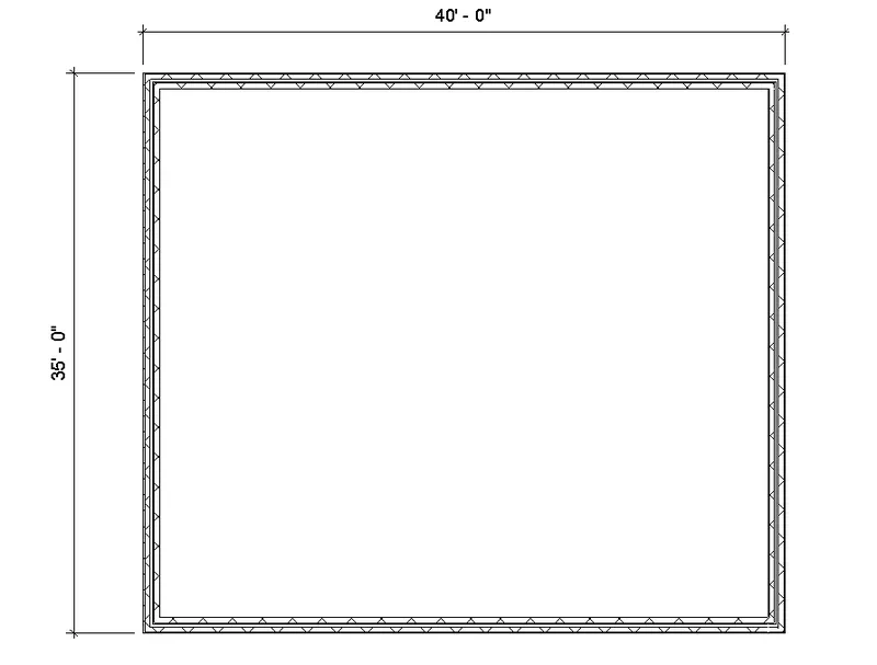
4) From the Annotate toolbar use the aligned option to add dimensions to the layout
STEPWISE PROCEDURE:
- To add dimensions to the created rectangular wall layout, go to the annotation tab and then select the aligned.
- The aligned option lets you create dimensions that are aligned with the objects regardless of their angle, slope, shape, or anything else.
- Press "UN" and check up on the length units.
- Set it to the fractional feet and inches and then apply and then ok.
- Press "DI" it and a small ribbon will be attached to the top panel.
- From the same ribbon, set up the dimension style like from which portion you want to start measuring.
- Set it up to the "FACE" to make it easy to measure the entire wall from the exterior to the exterior.
- Then go in the drawing and select the first face bring it on to the second face and then left-click.
- The dimension within the same distance with a dimension line will show up.
- Place the dimension according to the drawing need.
- Follow the same procedure and measure the second wall.
5) Use the properties browser to switch to different wall types
STEPWISE PROCEDURE:
- The left side of your Revit screen is dedicated to the properties panel where every property associated with the current or selected object is listed that can be changed accordingly.
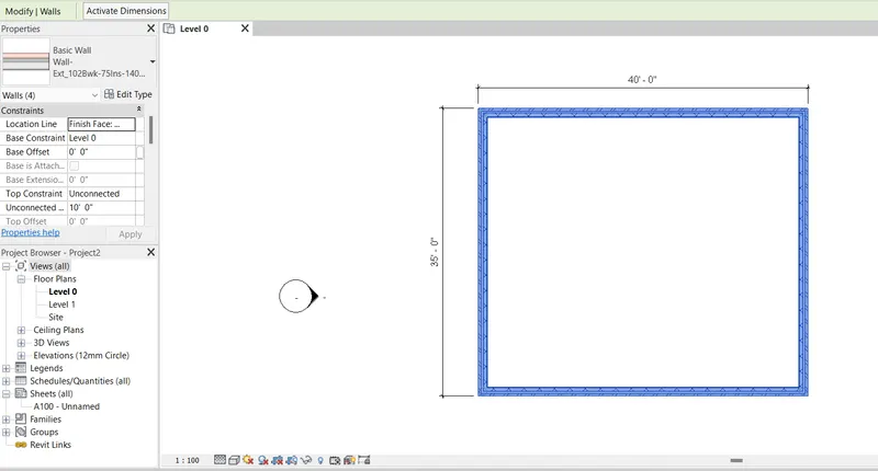
- So. select the entire rectangular wall section and look into the property panel.
- The top property of the wall is its type that is linked to a dropdown list.
- Click on the drop-down arrow to invoke various wall types within the architectural template.
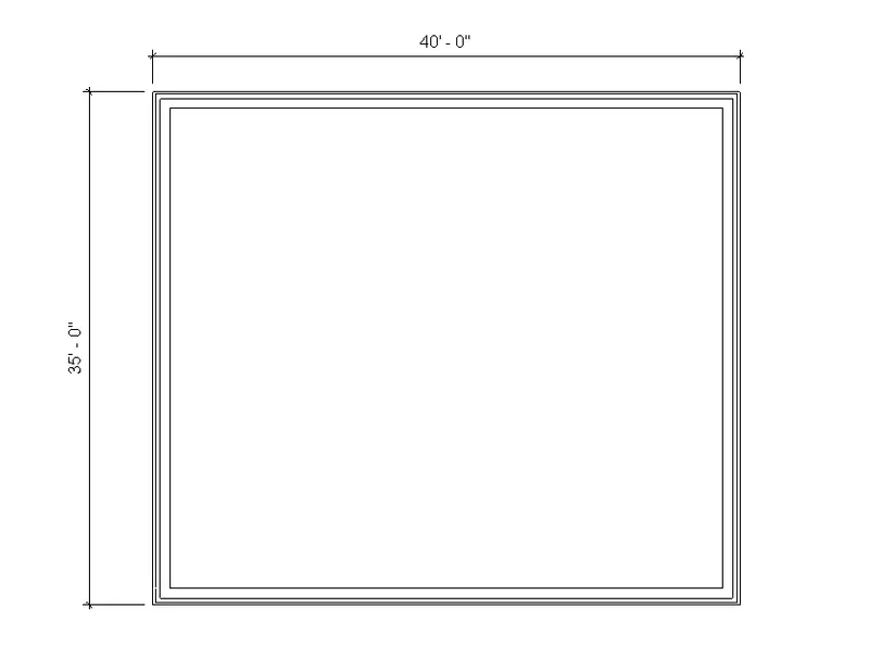
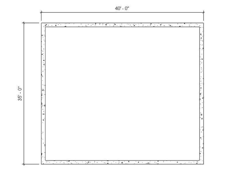
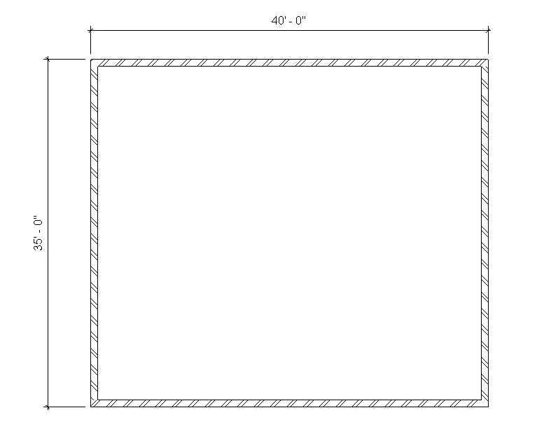
- Select the wall types as basic, concrete, and ext215bwk and showcase the changes made to the layout.
6) Create a 3D view from the view toolbar and save the view with the appropriate name
STEPWISE PROCEDURE:
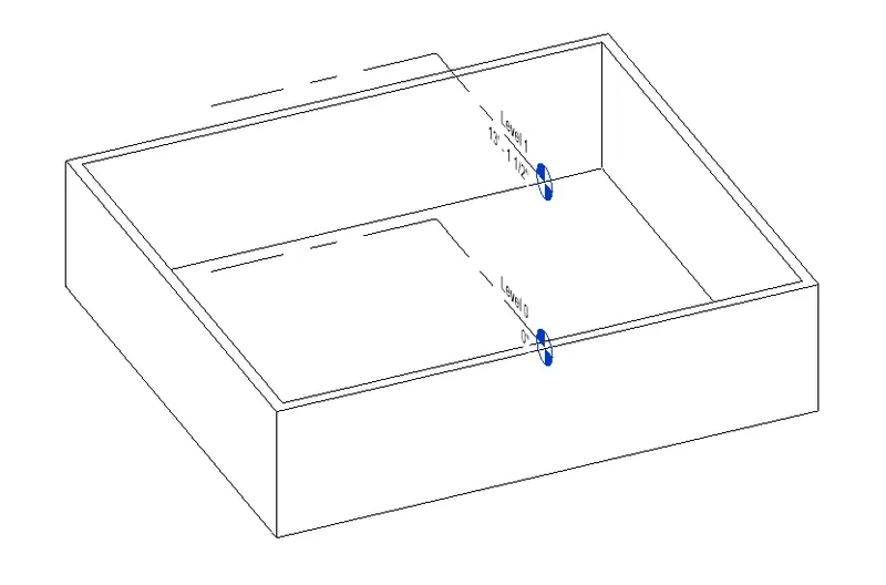
- To create the 3d-view of the created layout in Revit, you just have to shift the view to the 3d view.
- And to do the said, you can go to the view tab and simply select the basic 3d model from the dropdown list.
- A new window will be added with the 3d model of the current layout.
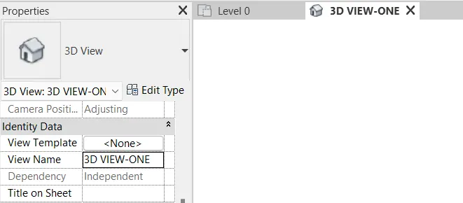
- And to name the same, you can change its identity from the properties panel.
- Thus, go to the properties panel and look for the identity data.
- And change the view name to "3D VIEW-ONE".
- The same change will show up in the 3d window name.
- Save the changes by pressing Ctrl+S.
7) Navigate through the 3D model using the view cube. Orbit/pan through the model layout created
STEPWISE PROCEDURE:
- Navigating through the 3d-model in Revit is very simple. You can do it through the view cube as well as by using your mouse.
- To navigate solely by using the mouse, press shift on your keyboard and then press the scroll wheel of your mouse.
- After doing the above, you can walk around the entire model by moving the mouse in the required directions.
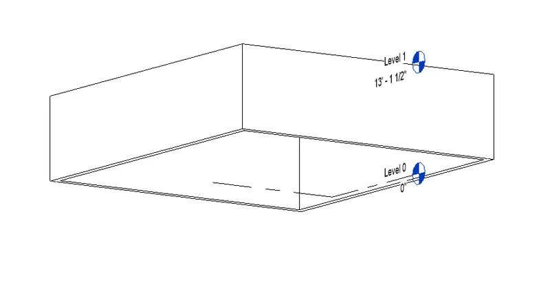
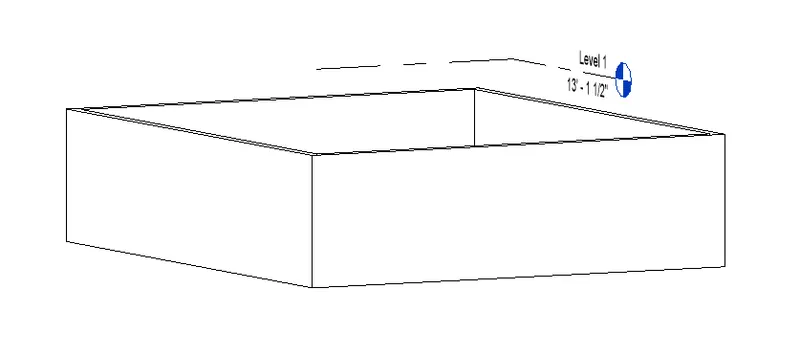
- The same method is used and the different 3d views are captured for the rectangular wall layout.
8) Use the visibility settings option below to switch model to shaded, realistic, hidden lines options
STEPWISE PROCEDURE:
- The visibility settings of the 3d model can be changed from the bottom left panel in Revit.
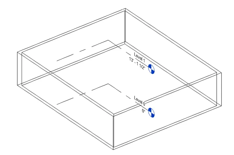
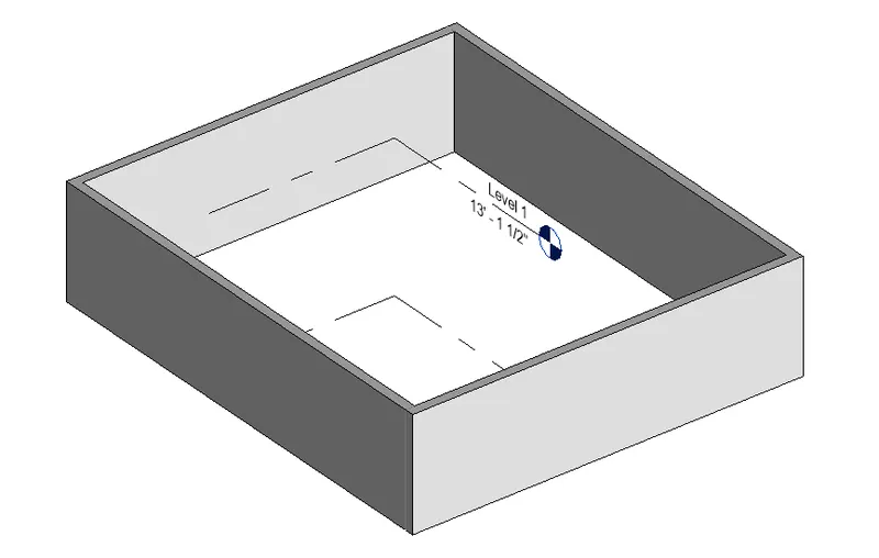
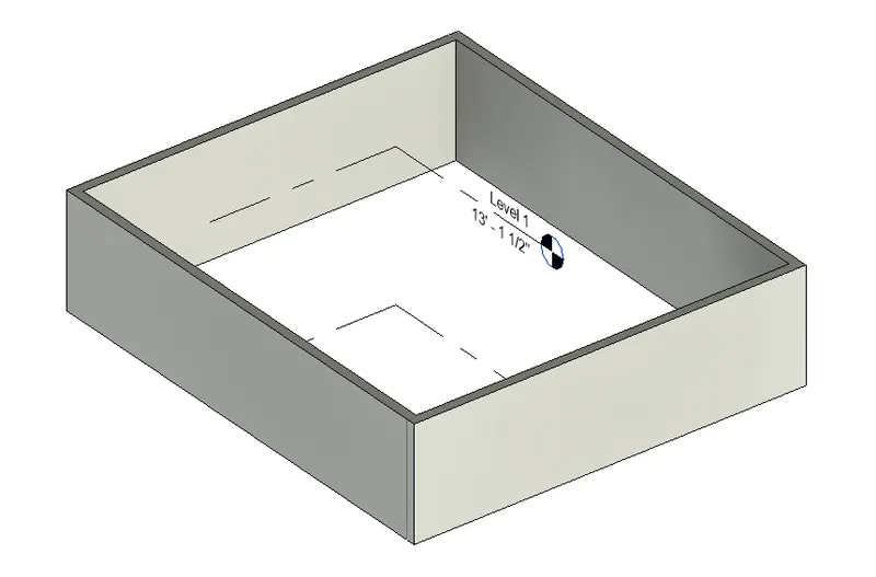
- Revit allows for various visual types like shaded, conceptual, realistic, hidden line, wireframe, etc.
- Thus, different visual styles are chosen for our rectangular wall section and the result is showcased below.
Wireframe model
Shaded model
Realistic model
9) Turn the sun path on and off to view shadings in the layout created
STEPWISE PROCEDURE:
- Click on the "Sunpath" from the bottom left tool line in Revit.
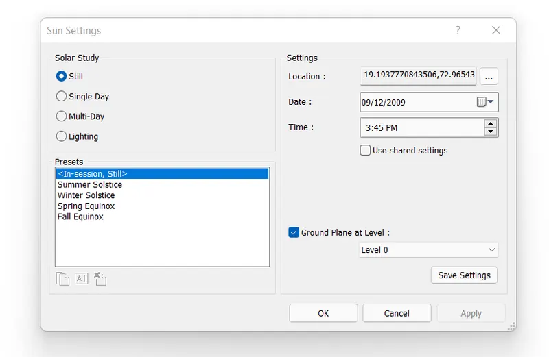
- Then, go to the sun settings to set up the location and other factors.
- A dialogue box with various options will show up.
- Within the same, select solar study as still.
- Choose the desired project location.
- Select the date and time and finalize the sun settings.
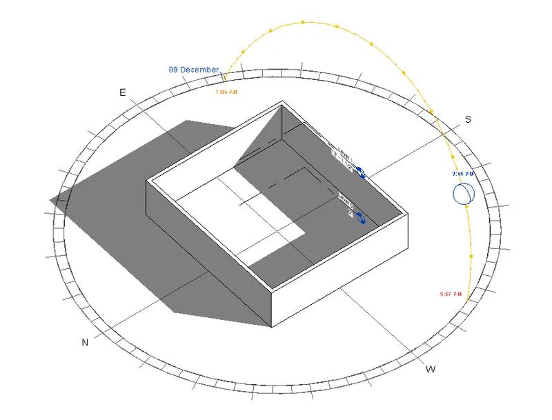
- After doing the settings, select the icon of "Sunpath on". A sun path will be displayed according to the location, date, and time.
- Now come back to the screen and click the "shadow on" option from the bottom left tools.
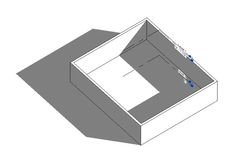
- It will display the accurate shadow conditions of the rectangular wall setup strictly as per the data entered in the sun settings.
- Similarly, you can put the sun path off from the same menu.
Sun Settings
Sun Path On
Sun Path Off
10) Use the Manage toolbar to enter project settings, project name, and project issue date (choose according to your convenience).
STEPWISE PROCEDURE:
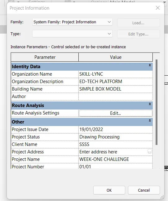
- Go to the Manage toolbar and select the project information tool.
- Then, enter all the project-related information within the dialogue box that will appear.
- Then click on OK, it will automatically save your input data.
11) What is the Analyze toolbar used in Revit? How it is beneficial for design and modeling
Analyze bar as the name suggests is used to carry out the structural analysis of the building. The tools and commands in the analyze toolbar let you set up the specifications for conducting a load analysis of the structure. Accordingly, you can put up the loading like point load, udl, etc according to the type of structure. The options available in the analyze toolbar will let your add up the loading configurations on all structural components such as slabs, beams, and columns. At the same time, you can set up the boundary conditions as per the structural requirements. Also, you can explain the load cases to the software which will enable it to perform precise calculations. And when you are done with all the settings and tools available in the analyze bar, you can go ahead and perform the extensive structural analysis of your building. Once the analysis is finished, it will take you to a different page where you can download the detailed report of your building's structural analysis.
12) What are the links that Revit supports to be linked to the model?
The link palette is included in Revit to make it easy for users to link different drawings to each other within a project. As a result, it becomes easy for Revit as well as your system to load different aspects of the project in a systematic manner. In addition, Revit allows for linking different Revit files and at the same time, you can also link a CAD file to your project in Revit. So, the type of links you can execute using Revit are explained below:
- Link Revit
Allows you to link multiple Revit models to one another in order to execute large projects more efficiently.
- Link IFC
Links IFC files to your current building project which adds as a reference to guide you through various stages of a project.
- Link CAD
Makes way for linking the CAD file to your Revit project. Any changes in the CAD file are notified in the Revit model and thus achieve better correlation.
- Link Topography
Topographical models created in the AutoDesk Civil 3D software are linked with the Current Revit Building. Any changes in the land topography shall be notified in the current drawing so as to facilitate a more precise building project in connection to the land on which the project is to be held.
13) Why do you need the Collaborate tab in Revit? How it supports modeling and its efficiency