Introduction to REVIT concepts
Q1) From the file menu, create a new project (Structural / Architectural / Construction template ) and name the project appropriately
AIM: To create a new project (Structural / Architectural / Construction template ) and name the project from the file menu
PROCEDURE:
STEP 1: Creation of new project
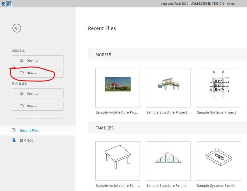
Open Revit software and click on new in models
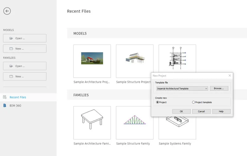
- After clicking new a pop up appears like this then select Template File as Imperial - Architectural template and in Create New select to Project and click OK
STEP 2: Naming the file
- From the top left corner select the File tab and it gives options like save/ save as (or) top left corner upper ribbon has a save file symbol like this
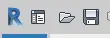 (or) we can give CTRL+S command
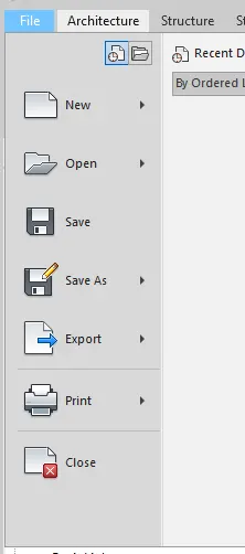
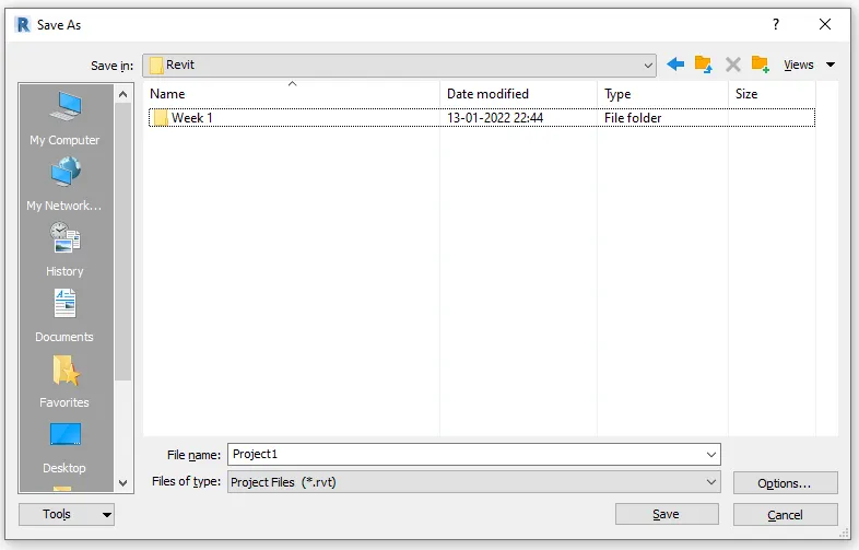
- Then save as pop up appears, name the file by the appropriate name and save to the desired location like below
RESULT:
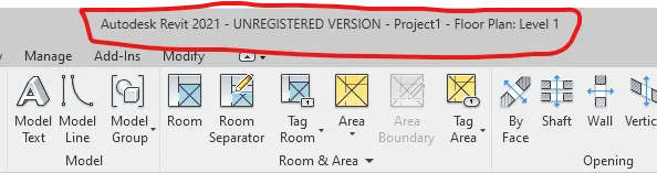
Q2) Save the new project file. Close and open using icons from file toolbar
AIM: To save the new project file by using close and open icons from the file toolbar
PROCEDURE:
STEP 1: Save the file and close
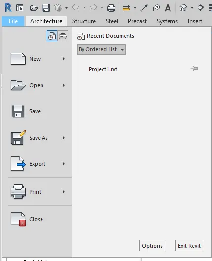
- Save as the file by assigning the name to it, Close the file from the File tab in ribbon and select Close icon to close
-
STEP 2: Open the saved file
- After opening the Revit software
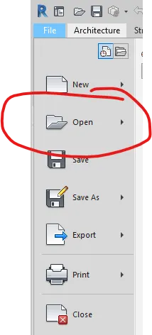
- From the File tab in the ribbon select the Open option and select project the previously saved file in the pop up
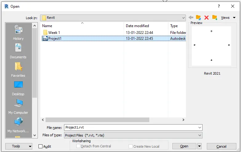
RESULT:
Q3) From the architecture/ structure toolbar familiarize with options to draw a wall. Create a rectangular layout of walls of about 40’-0” X 35’-0”
AIM: To create a rectangular layout of walls of 40'-0: x 35'-0" from the architecture/ structure toolbar
PROCEDURE:
STEP 1:
- Open Revit software
- Select new in models, select template as Architectural and select project in Create new
- Save the file as Project 1 in the file name to the desired location
STEP 2: Creation of rectangular wall
- Select the wall option in the Architectural toolbar
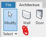 (or) give the command WA
 - Assign the wall in the dimensions of 40'-0" x 35'-0"
- while assigning wall from the Architectural toolbar the Revit automatically adds 8" wall thickness
RESULT:
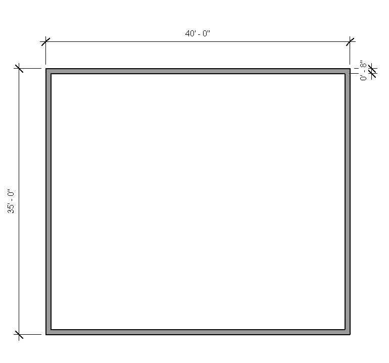
Q4) From the Annotate toolbar use the aligned option to add dimensions to the layout
AIM: To add dimensions to the layout by the use of aligned option from annotate toolbar
PROCEDURE:
- From the previously created wall assigning dimensions to it by using Annotate tab
- From Annotate toolbar select the linear palate to assign the dimensions to the created wall

RESULT:
Q5) Use the properties browser to switch to different wall types
AIM: To use the properties browser to switch to different wall types
PROCEDURE:
- By selecting the created wall with curser, the modify ribbon will appear, and in the modify toolbar select the properties palate
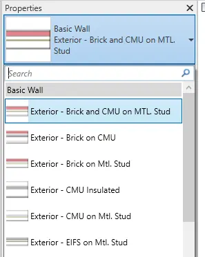
- It shows the created wall type like in this as Basic wall Generic - 8"
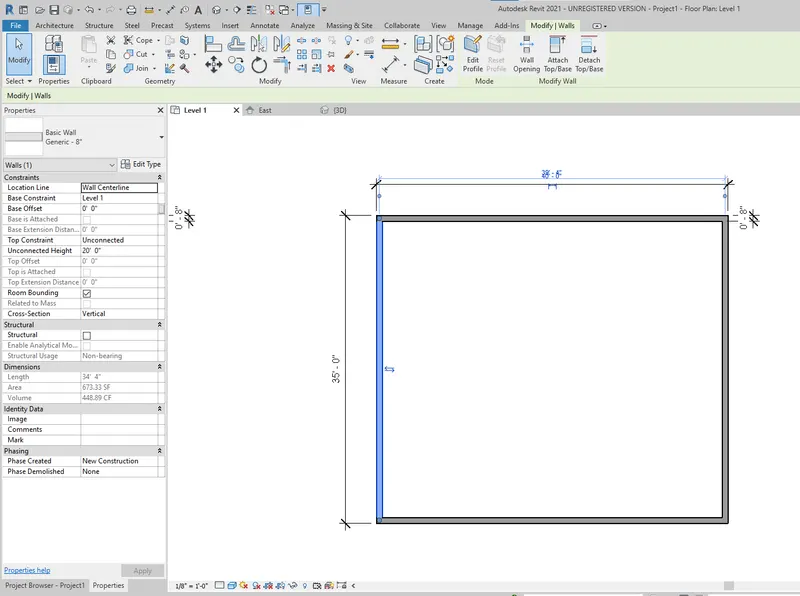
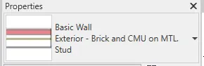
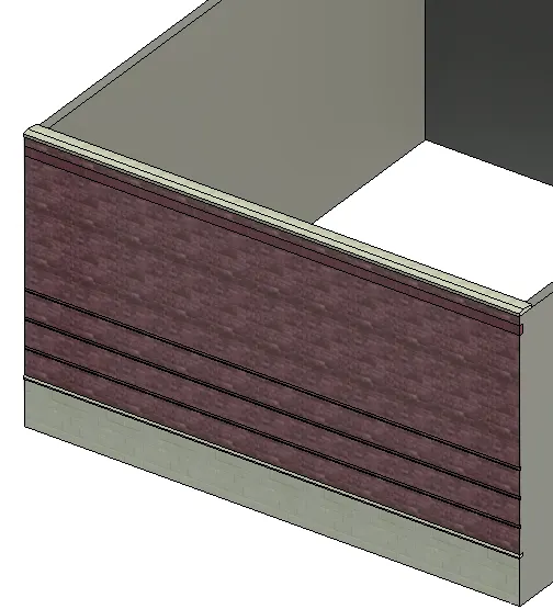
- Change Wall type desired one I'm selecting the Exterior - Brick and CMU om MTL. Stud
- Go to the 3D view from the view toolbar and select the cube at the left bottom corner
 and select to Realistic so we can see the texture of the assigned wall type
RESULT:
Q6) Create a 3D view from the view toolbar and save the view with the appropriate name
AIM: To create a 3D view from the view toolbar and save the view with the appropriate name
PROCEDURE:
STEP 1:
- Open the view toolbar and select the 3D view option
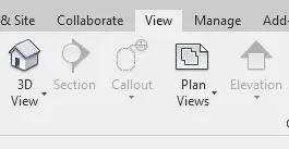 so the created 2D model changes to 3D view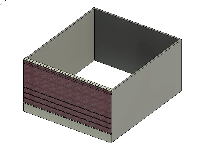
- Right-click on the view cube so that pop up appears and select save view -> assign an appropriate name
RESULT:
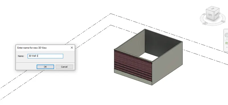
Q7) Navigate through the 3D model using the view cube. Orbit/pan through the model layout created
AIM: To Navigate the 3D model using View cube
PROCEDURE:
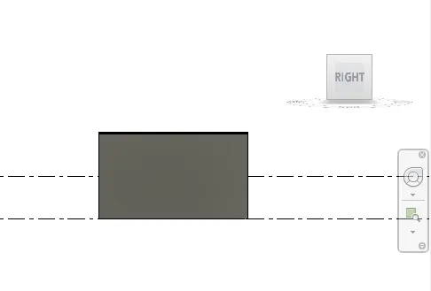
- Select the different views from the view cube Like Top, Right, etc.,
RESULT:
TOP VIEW RIGHT VIEW
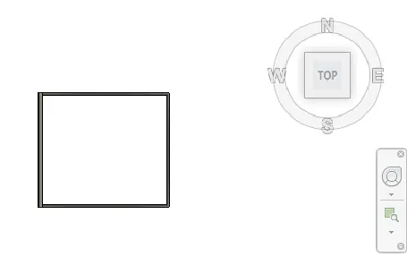
Q8) Use the visibility settings option below to switch model to shaded, realistic, hidden lines options
AIM: To use the visibility settings option below to switch model to shaded, realistic, hidden lines options
PROCEDURE:
- select the cube at the left bottom corner
 select the different visibility options
 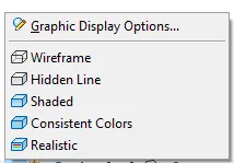 for the model
RESULT:
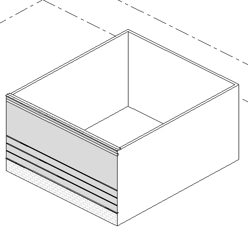
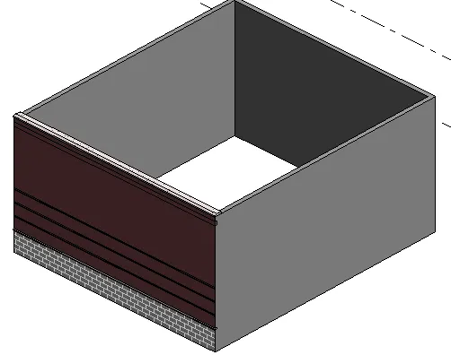
HIDDEN LINE SHADED REALISTIC
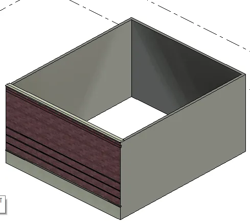
Q9) Turn the sun path on and off to view shadings in the layout created
AIM: To turn the sun path on and off to view shadings in the layout created
PROCEDURE:
- Select the sun path option from the left bottom corner and it pop-ups as sun path off and sun path on
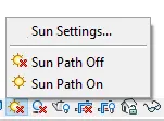
RESULT:
SUN PATH ON  SUN PATH OFF
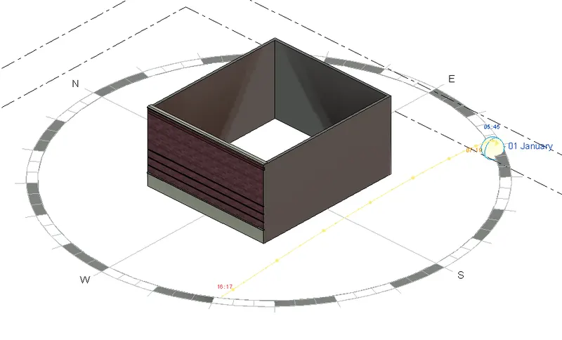
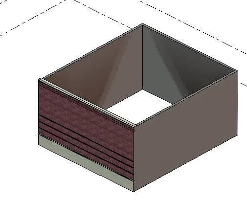
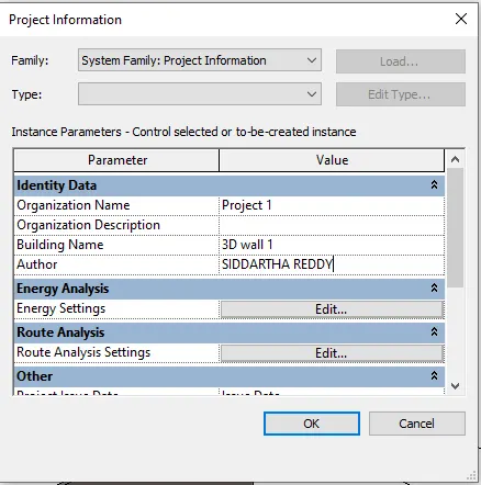
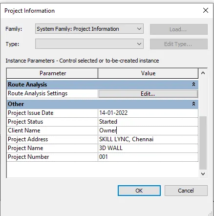
Q10) Use the Manage toolbar to enter project settings, project name, and project issue date (choose according to your convenience).
AIM: To use the manage toolbar to enter project settings, project name, and project issue date
PROCEDURE:
- From the manage, toolbar select the Project information
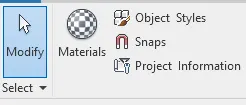 and assign the detiles
RESULT:
Q11) What is the Analyze toolbar used in Revit? How it is beneficial for design and modeling?
ANS: Analyze toolbar is used in the analytical model where we can provide Boundary conditions, loads, load cases, and combinations to the model and also Energy optimization to the model. It is beneficial that we can check structure conditions in the software itself.
Q12) What are the links that Revit supports to be linked to the model?
ANS: In the INSERT toolbar the different types of links supported by Revit that can be linked, some of them are
LINK REVIT: It links another Revit model to the current model.
LINK IFC: It links Industry Foundation Classes (IFC) to the current Revit model.
LINK CAD: It links the CAD file to the current Revit model.
Q13) Why do you need the Collaborate tab in Revit? How it supports modeling and its efficiency
ANS: When the Architect, Civil, and MEP engineers work on the same project and the same model the collaborate toolbar gives many beneficial options to like
Collaborate: It gives simultaneous workflow of the team members on the particular model
Worksets, Editing requests, Synchronize, work-sharing monitor, etc., all these options from Collaborate tab efficient to reduce Time, cost and increase the precision of detailing to the model.