Introduction to REVIT concepts
Name: Allan Bryan Jayson Cruz
Course: Master’s Certification Program in High-Rise Building Design & Analysis
Date: December 12, 2021
Challenge 1_ Introduction to REVIT concepts
********************************************************
1. Aim & Introduction
***************
Aim
This challenge aims to familiarize the student with the Revit Software. It introduces the student to the Revit interface, Revit tools, and how to utilize them.
Introduction
Revit is a building information modelling software that allows the user to create and design a 3D model building structure. It is an engineering software where the user can provide 3D illustration of the building as well as its design.
********************************************************
2. Detail Procedure
***************
1) From the file menu, create a new project (Structural / Architectural / Construction template ) and name the project appropriately
PROCEDURE:
- Open the Revit software by double clocking the Revit icon.
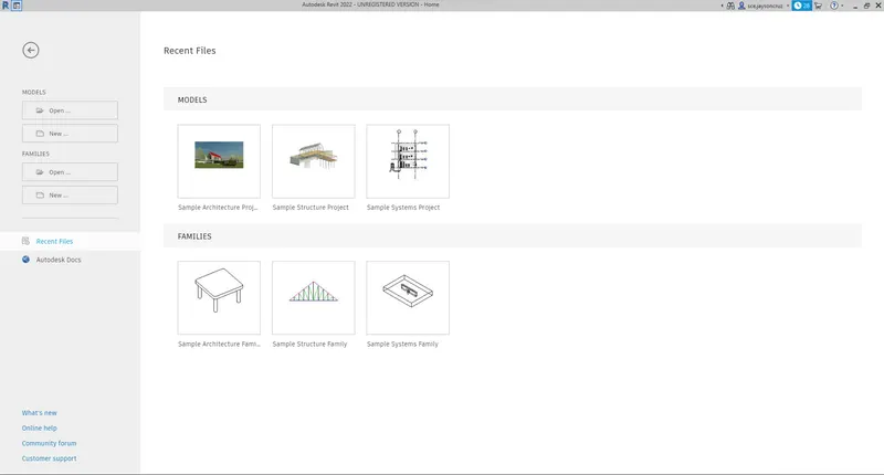
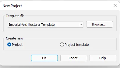
- Click "New". The "New Project" window will appear. Select the template file and clikc OK.
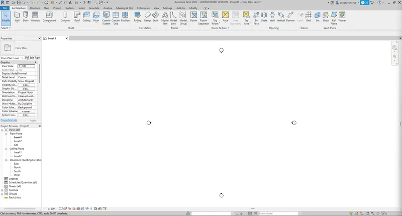
- The Revit interface will appear.
- To create a new project from the file menu, go to "File"-->"New"-->"Project".
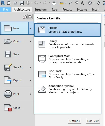
- The same window will appear as earlier.
***************
2) Save the new project file. Close and open using icons from file toolbar
PROCEDURE:
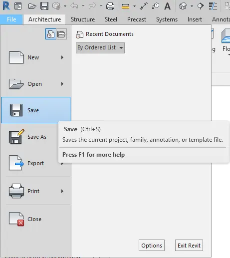
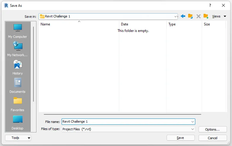
- Save the Revit model and name it appropriately.
- File Menu --> Save.
- Specify the name and location.
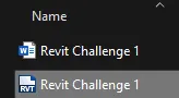
- The model will be saved in the specified folder with the specified name.
***************
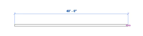
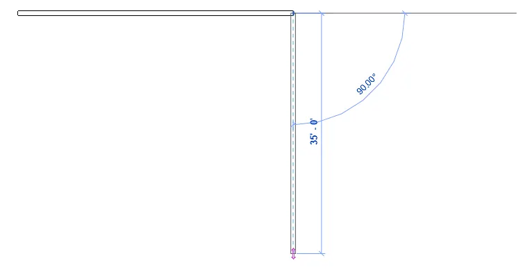
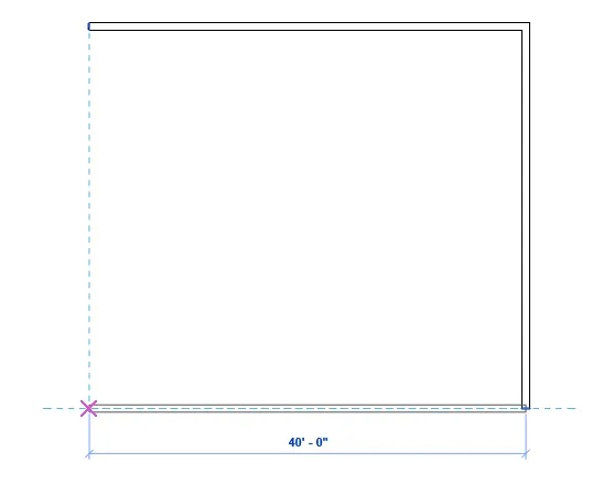
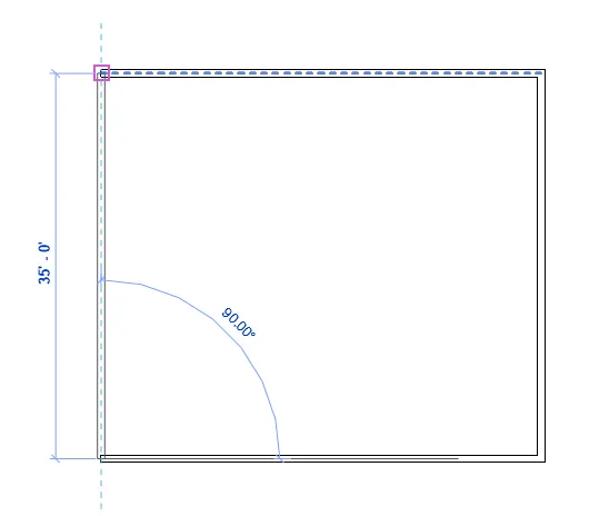
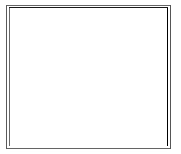
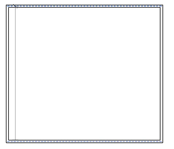
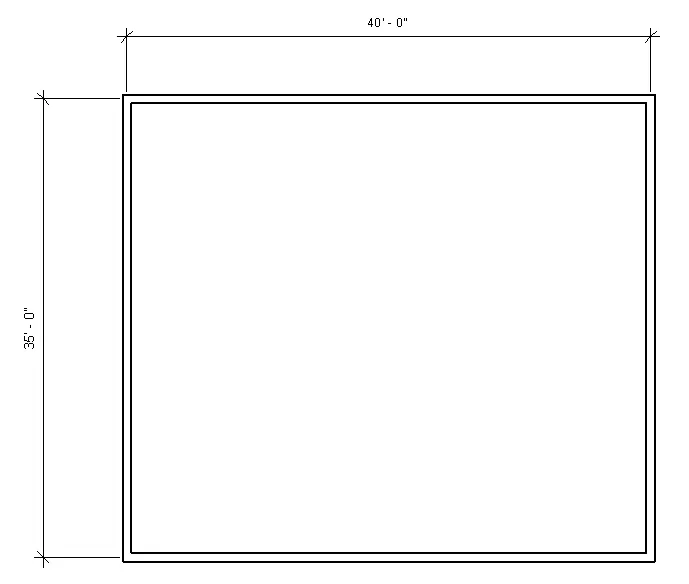
3) From the architecture/ structure toolbar familiarize with options to draw a wall. Create a rectangular layout of walls of about 40’-0” X 35’-0”
PROCEDURE:
- Use the "Wall" tool to create the wall.
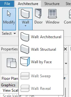
- Once you click the Icon, create the wall on the interface.
***************
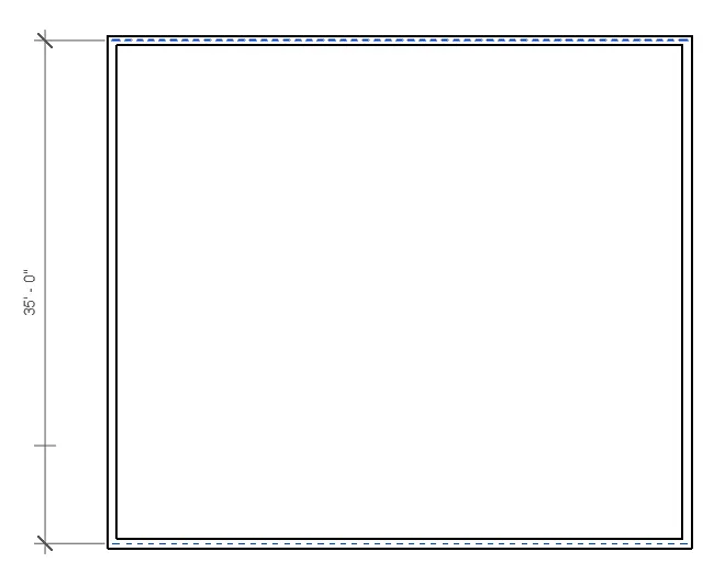
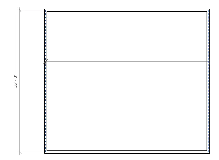
4) From the Annotate toolbar use the aligned option to add dimensions to the layout
PROCEDURE:
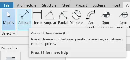
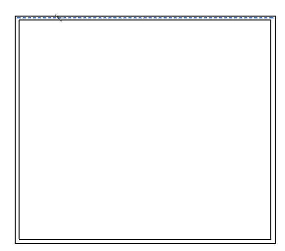
- To add dimension, go to "Annotate" tab and click aligned option.
- Use the mouse cursor to apply dimension.
***************
5) Use the properties browser to switch to different wall types
PROCEDURE:
- To select a different type of the wall. Go to Modify tab and select the "Type Properties" icon.

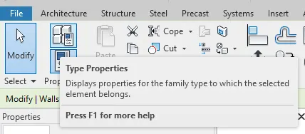
- The type properties will appear. Change the type of the selected wall in here.
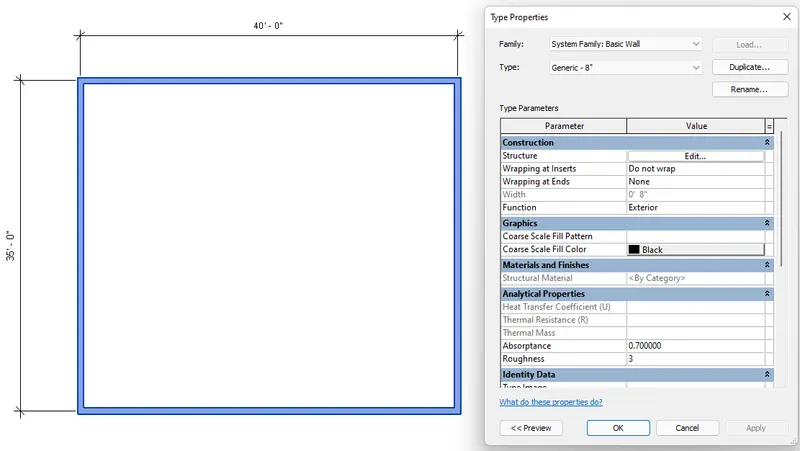
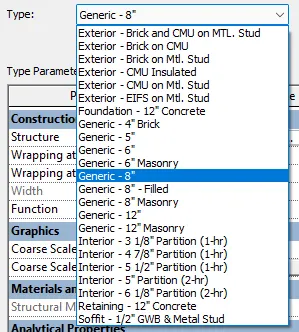
- Sample type "Retaining -12" Concrete".
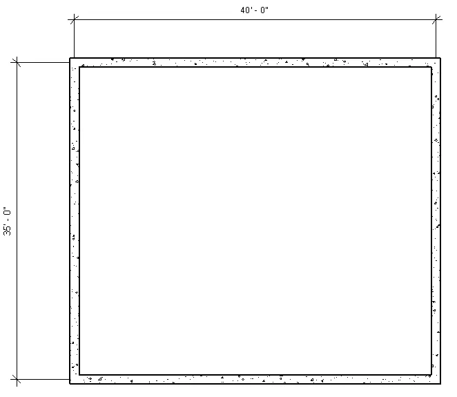
- The type of the wall will change.
***************
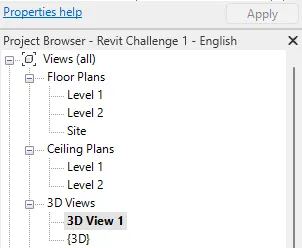
6) Create a 3D view from the view toolbar and save the view with the appropriate name
PROCEDURE:
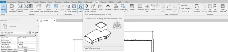
- Go to the "View" menu bar and select "3D view".
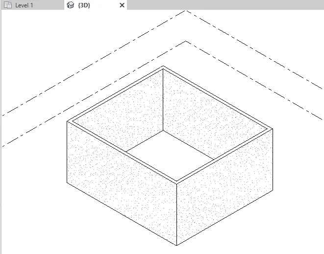
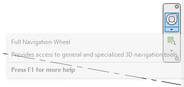
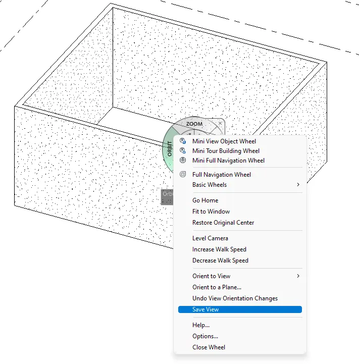
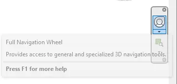
- Click the "Full Navigation Wheel" at the right.
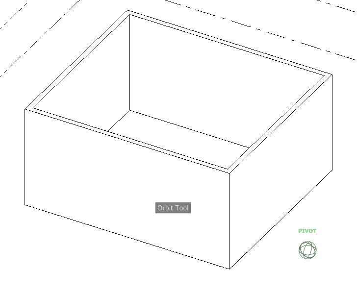
- Navigate to a desired 3D view. Then save by right clicking on the model and clicking "Save View".
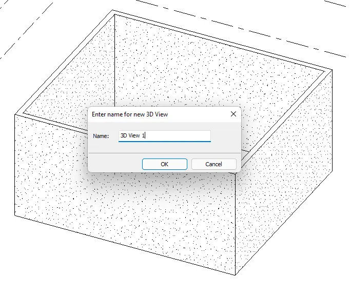
- Name the view and click Ok.
***************
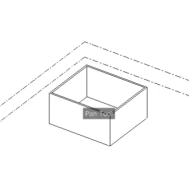
7) Navigate through the 3D model using the view cube. Orbit/pan through the model layout created
PROCEDURE:
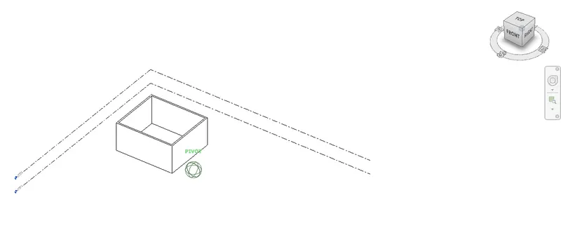
- To use the view cube, click the icon on the upper right of the interface.
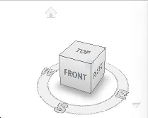
- Click the desired view.
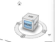
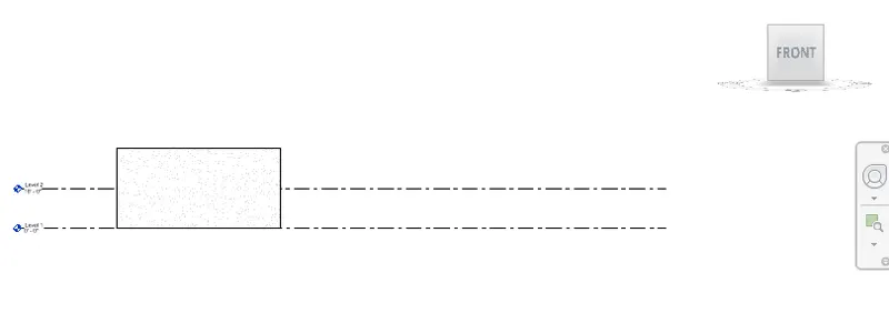
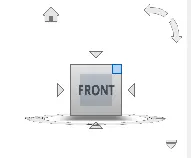
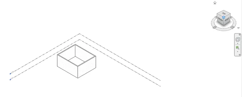
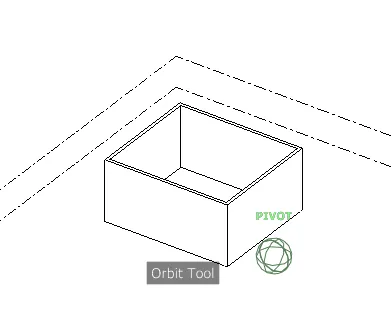
- Aside from clicking, you can hold the icon to pivot the model.
- Moreover, Revit has a navigation wheel that allows the user to "Pan, Zoom, Orbit, Rewind, Center, Walk, Look, and Up/Down".
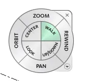
- Hold on the desired option and drag to desired position.
***************
8) Use the visibility settings option below to switch model to shaded, realistic, hidden lines options
PROCEDURE:
***************
9) Turn the sun path on and off to view shadings in the layout created
PROCEDURE:
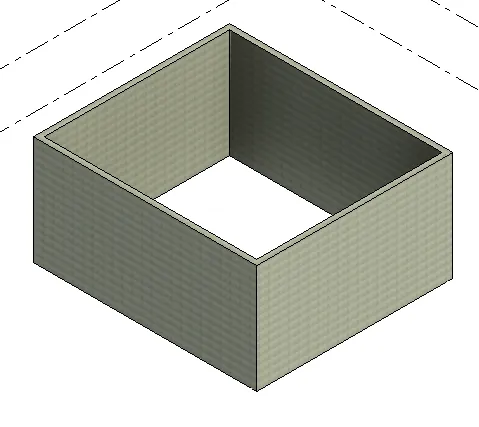
- The visibility options is located at the bottom part of the interface.
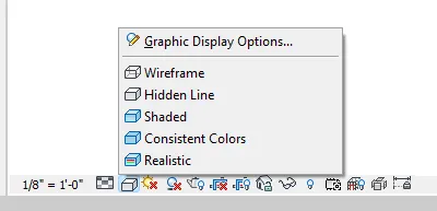
- Click on the preferred view and see the changes.
--> Wireframe
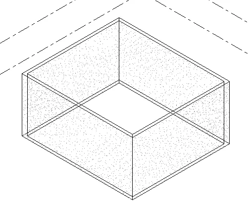
--> Hidden Line
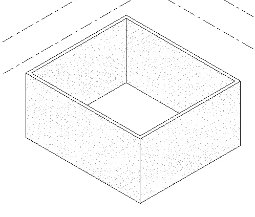
--> Shaded
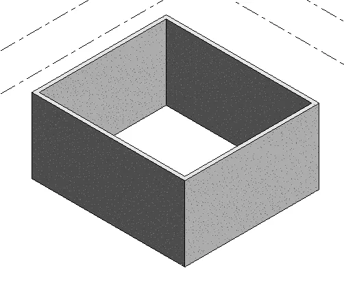
--> Consistent Colors
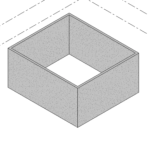
--> Realistic
***************
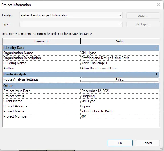
10) Use the Manage toolbar to enter project settings, project name, and project issue date (choose according to your convenience).
PROCEDURE:
- Go to the Manage toolbar at the top of the interface.

- Go to Project Information.
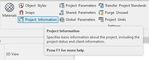
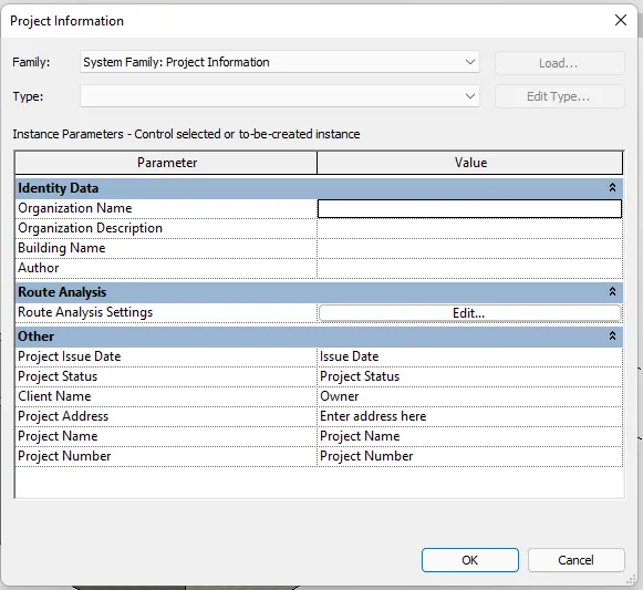
- Fill-in the required information. Once entered, click Ok.
***************
11) What is the Analyze toolbar used in Revit? How it is beneficial for design and modeling
The Analyze tab is as shown below.

The analyze tab is used to check or evaluate the building performance and sustainability. This tab allows the addition of design loads and load combinations. It also allow the specification of boundaries in the current model.
This tab allow the creation of the Energy models that allow the user to investigate or evaluate the energy sustainability of the current model. This feature helps generate the energy analytical model that determines the models eco-friendly traits.
It also allows the user to check and see the status of the building and its components such as Ducts or Pipes that are present in the model.
All the analysis made by each user will be present in the Results Manager.
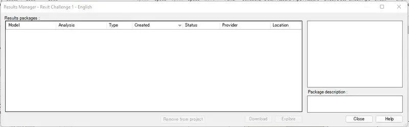
Once the results are checked, the users or the engineers will be able to evaluate if the current model is already adequate or if there are any changes that are to be made.
***************
12) What are the links that Revit supports to be linked to the model?
The links provided by Revit are as follows:

Link Revit - Links another Revit model to the current model. Models are linked together to specify the relative locations of different buildings orcoordinate efforts accross other engineering disciplines.
Link IFC - Links and IFC file to the current project to reference its information for additional design work.
Link CAD - Links a CAD file to the current Revit Model.
Link Topography - Links existing topography to the current Revit Model. This tool is used when a civil engineer has created a topgraphy using civil engineering software such as Autodesk Civil 3D, and you want to use the topography to provide context for the building model.
DWF Markup - Links marked-up DWF files into a Revit project so you can see the markups on corresponding sheets.
Point Cloud - Links a Point Cloud file into the current project. It can also be used to index a raw format point cloud file for use in a project. When linked into a project, point clouds can provide references when you are placing or editing model elements.
Coordination Model - Links a NWD or NWC file to provide context for the Revit model. This feature allows you to compare your Revit model to a non-Revit model for coordination purposes.
These links can be managed using the "Manage Link" to control the links.
***************
13) Why do you need the Collaborate tab in Revit? How it supports modeling and its efficiency
The collaborate tab in the Revit Software is the ability of the software to allow all kinds of engineering discipline to work together at the same time. The collaborate tab is as shown below.

This tab is a function of the Revit software to allow multiple users to work on a single model simultaneously. This is a way to enter different parameters or elements in the model as well as informing all users when changes are made. It allows faster and more efficient project since communication between users will be easier. Since Revit is a real time changing model, this creates new informations immediately. This function can also be used for clash checking between other disciplines.
********************************************************
3. Conclusion
***************
The Revit software is a revolutionary engineering software the allows not only one user but also multiple users to work on a single 3D model structure. These users can come from different engineering disciplines and collaborate together to finish the project. The revit software create this environment to order to provide efficient project management, modelling and design.
Revit also provides multiple 3D and 2D features that help the user to perform Architectural and Structural Analysis. It helps the user sketch and analysis the building structure in a single software. This proves to be a revolutionary technology in the engineering industry as it will help complete a building structure where all elemets are present and evaluated.