Internal Geneva Mechanism
AIM :
Design the Internal Geneva Mechanism
OBJECTIVE :
- Create 3D models for driver and driven wheels.
- Perform motion analysis by rotating the driver wheel at 10rpm for 1st study and 20 rpm for another study.
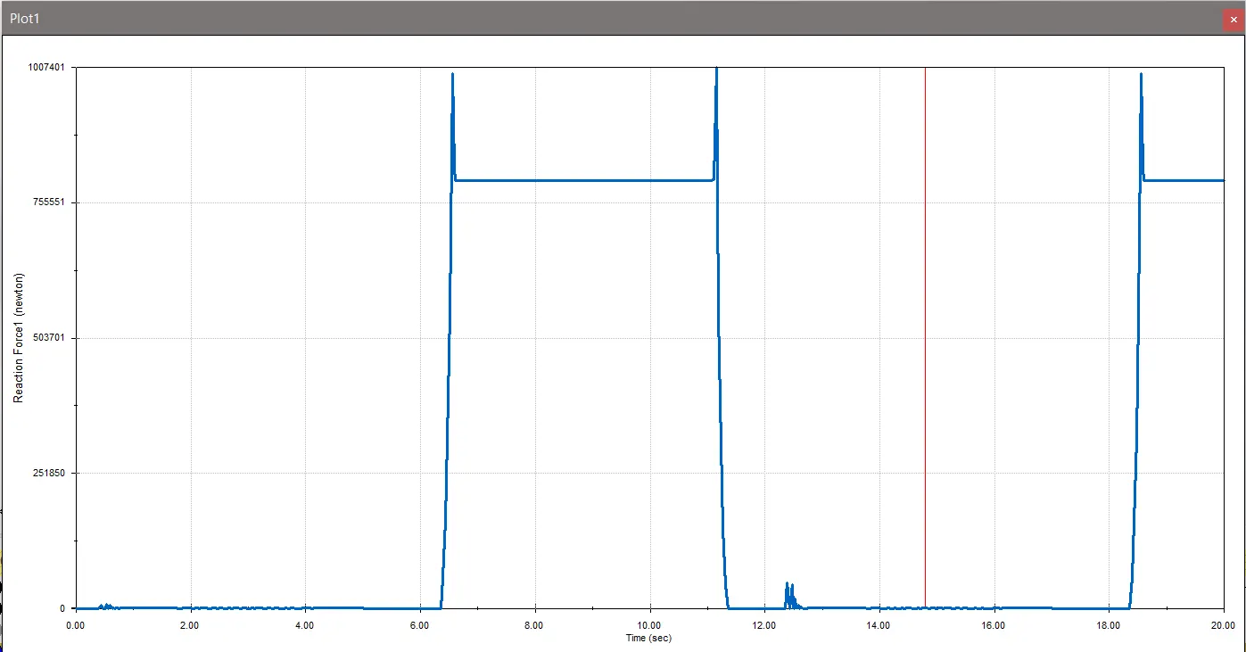
- Obtain the Results for Contact force (between driving and the driven wheel) as a function of time, angular displacement of the driven wheel & then driver wheel's angular velocity with and without "Precise contact"
INTRODUCTION :
An internal Geneva drive represents a unique variation in design. In this configuration, the drive wheel's axis is supported on just one side.The angle through which the drive wheel must rotate to initiate a single step of the driven wheel is consistently less than 180° for an external Geneva drive, while it exceeds 180° for an internal one. This difference results in a longer switch time for the internal Geneva drive, prolonging the duration during which the driven wheel remains stationary.
THEORY :
The Geneva drive is a gear mechanism that translates a continuous rotation movement into intermittent rotary motion.The rotating drive wheel is usually equipped with a pin that reaches into a slot located in the other wheel (driven wheel) that advances it one step at a time. The drive wheel also has an elevated circular blocking disc that "locks" the rotating driven wheel in position between steps.
Types of Geneva drives are Follows:
1) External Geneva Drive
2) Internal Geneva Drive
3) Spherical Geneva Drive
Applications of Geneva Mechanism :
1) The common application of Geneva Drive is Movie Projectors.
2) Wrist Watches.
3) Plotters – Plotter is a computer printer for printing vector graphics.
4) Automated sampling machines.
5) Banknote Counting Machines.
PROCEDURE :
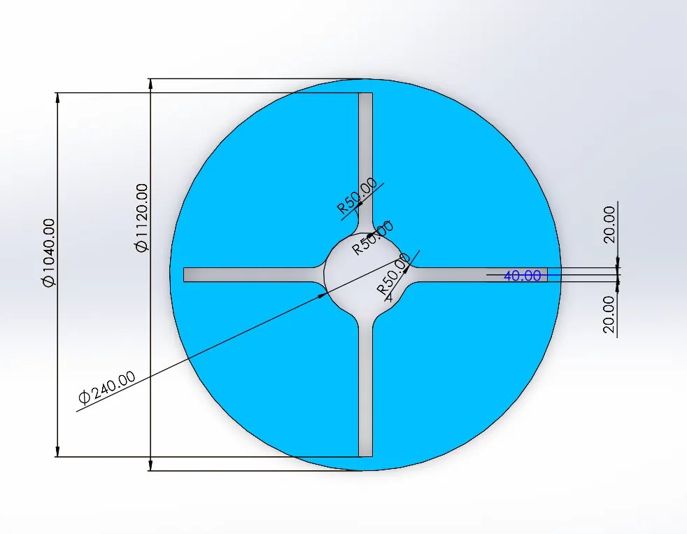
- Create a 2D sketch for the Driven Wheel according to the provided dimensions.
- Transform the 2D sketch into a 3D part model and save it as a part file.
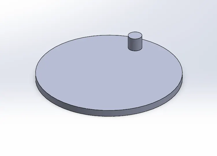
- Create a 2D sketch for the Drive Wheel of the internal Geneva drive based on the given dimensions.
- Convert the 2D sketch into a 3D part model and save it as a part file.
- Begin a new assembly part file.
- Import both the part files for the Drive Wheel and the Driven Wheel of the internal Geneva drive.
- Use mates to assemble the Drive Wheel with the Driven Wheel, ensuring they are properly aligned and at a specific center-to-center distance.
- Save the assembled assembly file separately.
- Open the assembly in a new window for motion analysis.
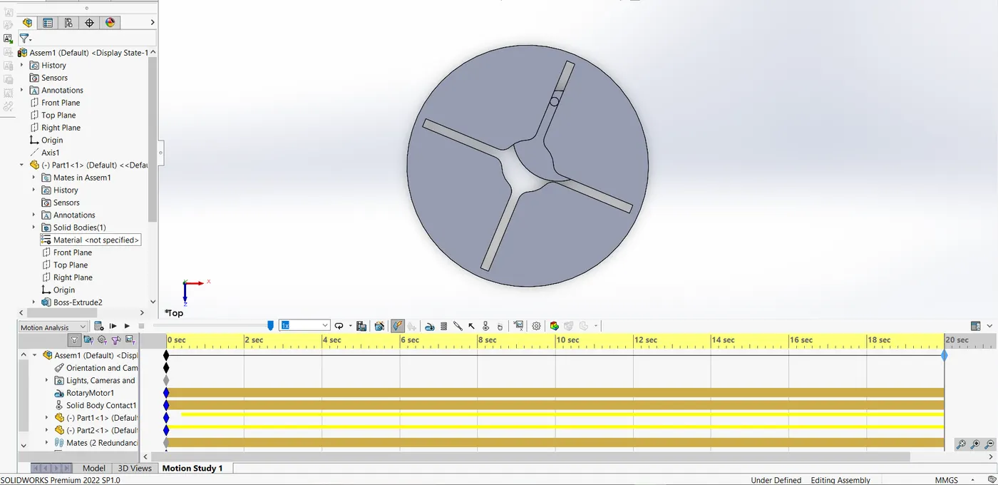
- Set up a motion study, choose motion analysis, and configure the necessary parameters.
- Add a motor to the center axis of the Drive Wheel, initially set at 10 RPM.
- Implement solid contact surfaces for the mechanism, specifying the materials for the Drive Wheel and Driven Wheel.
- Calculate the contact force between the Drive Wheel and Driven Wheel, display the results in plots.
- Select angular displacement for the Driven Wheel and angular velocity for the Drive Wheel.
- Set the frame count to 60 for the 10 RPM motor, and then to 120 frames for the 20 RPM motor, both with and without precision contact.
- Click on the "Calculate" option and initiate the animation to obtain the final results.
Parts Created:
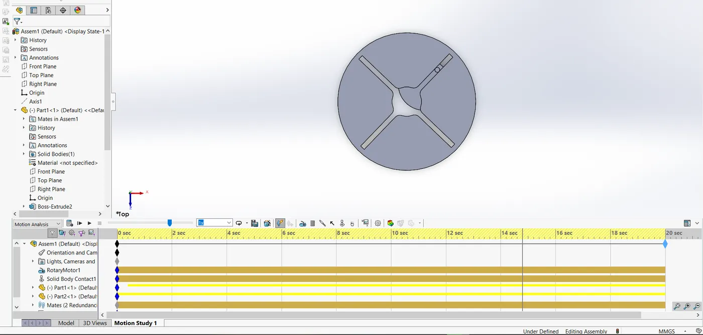
Motion Study Performed:
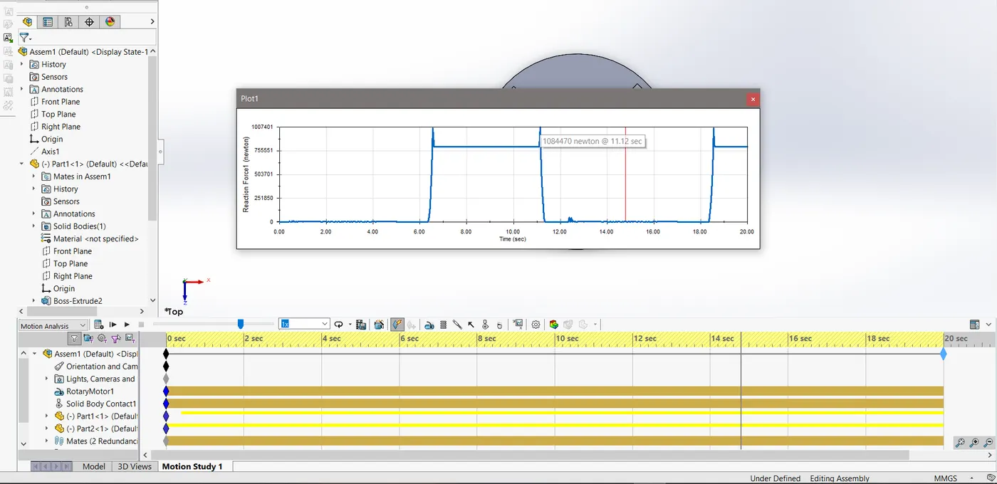
Final Results: