Internal Geneva Mechanism
1. Objective:
1.1 To Create 3D models for driver and driven wheels.
1.2 Perform motion analysis by rotating the driver wheel at 10rpm.
1.3 Obtain the following plots:
- Contact force (between driving and the driven wheel) as a function of time. - Angular Displacement of the driven wheel.
1.4 Compare the contact forces with and without "Precise contact." - Showing image for precise contact selection.
- Export the results that we get to Excel and make the plots over there.
2. Basic:
The Geneva drive or Maltese cross is a gear mechanism that translates a continuous rotation movement into intermittent rotary motion. the difference between Geneva Drive mechanisms and other gears is that Geneva Drive mechanisms have unusual teeth. Unlike in typical gears, the interaction between the part being driven and the part doing the driving is not continuous and the resultant motion is intermittent. Geneva Drives work by having the driving part, or wheel, interlocking with the driven part intermittently. The number of spokes that the driven part has and the speed with which the driving part rotates determines the frequency and distance of travel. There is an elevated segment on the driving wheel which keeps the driven part in position till the next revolution is complete. The external Geneva Drive is by far the most common type, although there are other variations possible in the design. The external drive can be built to withstand higher levels of stress and are generally more robust and sturdy than other variants.
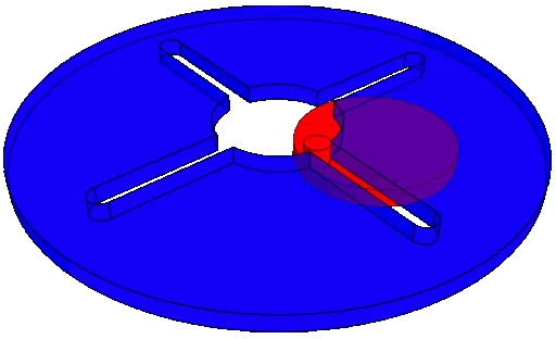
Fig: Internal Geneva Mehanism
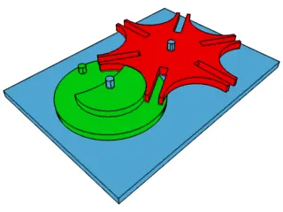
Fig : External Geneva Mechanism
The Internal Geneva Drive has the driving part below the driven wheel, with the driving part often being much smaller than the driven wheel. the axis of the drive wheel of the internal drive can have a bearing only on one side. The angle by which the drive wheel has to rotate to effect one step rotation of the driven wheel is always smaller than 180° in an external Geneva drive and always greater than 180° in an internal one, where the switch time is, therefore, greater than the time the driven wheel stands still.
3. Procedure:
To do motion analysis of internal Geneva mechanism first we need to design 3D parts of the Geneva mechanism. Hence, to do that we are going to design individual part in Solidworks. i.e first part is the driving wheel and the second part is a driven wheel based on the following 2D drawing.
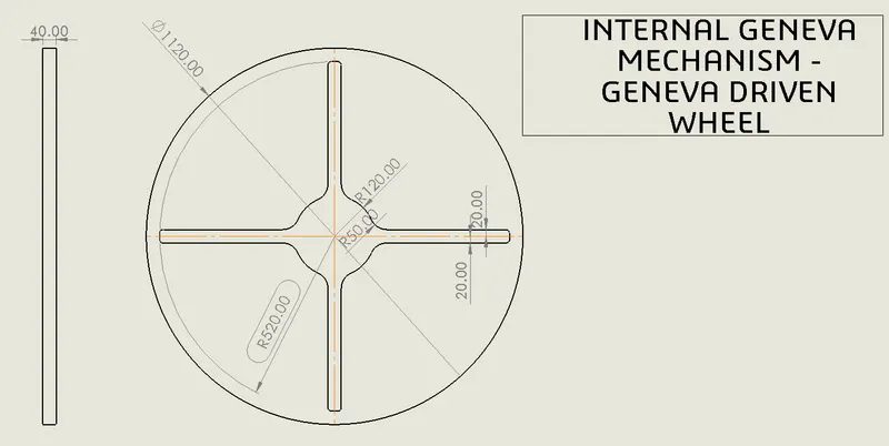
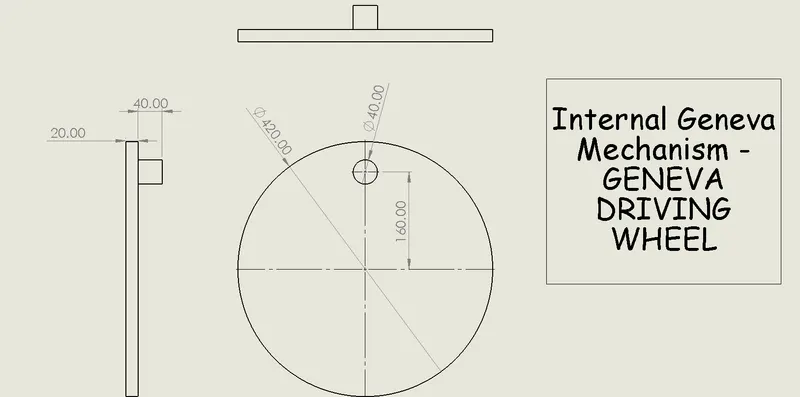
fig. 3 2D Drawing of Diver and Driven Wheel.
To do part design, open Solidworks software > choose a new option > choose a part design option. before designing part we need to verify our unit system which is as MMGS (i.e Millimeter, Gram, Second).
3.1 Driver part:
We are going to design our first part which is Driving wheel based on 2D drawing. first select front plane and choose the option for sketching, draw a circle at Axis with diameter 420-millimetre diameter, similarly draw a small circle with diameter 40 millimetres and at a distance of 160 mm from the centre.
After completing 2D sketching we are going to use the Extrude option. to make the 2D drawing into 3D. Extrude Larger circle and smaller circle with 20 mm and 40 mm respectively, the final result of the first part is as shown below.
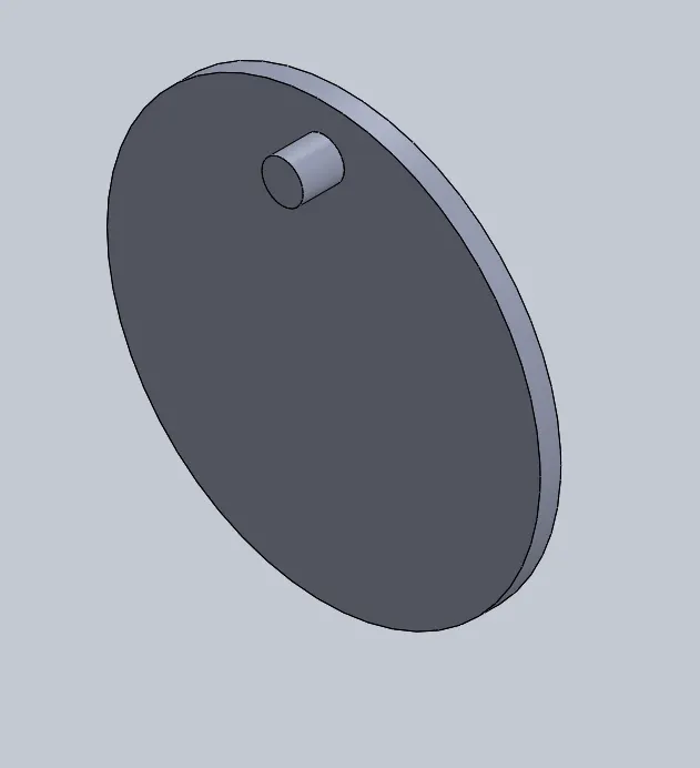
fig. 4 Driving Wheel
After completing the driver part we are going to save it as a name of driving Wheel on our computer.
3.2. Driven part:
our second part is driven part which is known as Driven wheel. again we are going to use front playing as a sketching plane. now Drawing a circle with diameter 1120. our driving wheel has slots for moving part of driver wheel. hence to draw a slot in the driven wheel we are going to draw x and y-axis as a reference.
Using offset with
after that, we are going to draw Internal circle with radius 120 millimetre
which has Fillet of the 50-millimetre radius.
Extruding with 40 millimetres.
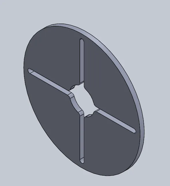
fig. 5 Driven Wheel
After completing our driven part we are going to save it as a name of driven wheel in our computer.
3.3 Assembly Design:
To do motion analysis we are going to assemble the parts which we are designed previously. for more convenient we are using part 1 name for driving wheel and part 2 name for the driven wheel. first, we are going to open a new file and select assembly by taking the unit in consideration
Now, we are importing two parts in an assembly.
1) Open a new assembly model. Open The driven and driver model. Right click the driven part and click Float, so it can be moved around.
2) Next click on the mate option. Under entities to mate, select the Front Plane of the driver and the Front Plane of the assembly. Click on coincide.
3) Go to the View options, and select Hidden Axis. The hidden axes are now visible.
4)Next mate the central axis of driver and the Top Plane of the assembly. Click on coincide.
5) Then mate the central axis of driver and the Right Plane of the assembly. Click on coincide.
6)Similarly, mate the central axis of driven component and the Right Plane of the assembly. Click coincide.
7) Then mate the Front Plane of the driven component and the Front Plane of the assembly. Keep the distance as 40mm.
8) Finally, mate the central axes of the driver and driven component. Keep the distance as 226.27mm.
9) Assembly is now complete.
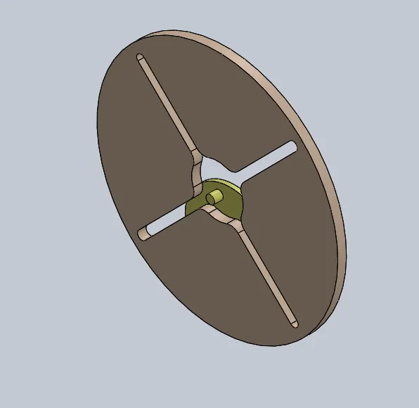
3.4 Simulation and Analysis:
To do simulation and analysis (i.e motion analysis) we are going to choose the Solidworks motion option from Solidworks Add-Ins. now we can see that the motion analysis option which is shown below in the window of Solidworks.
To Rotate the Driving wheel we are going to assign motor for driving wheel. to do that select motor option in motion analysis and select part 1 axis. after that, we are going to assign solid body contact by selecting contact option and selecting part 1 and part 2. from Menu we can assign a material to the parts.
To analyse multiple parameters, we can use a plot option in motion analysis, the plot results as follows.
3.4.1 Analysis at 10 RPM:
1. Contact force:
The plot of contact force between driving and the driven wheel as a function of time is as follows.
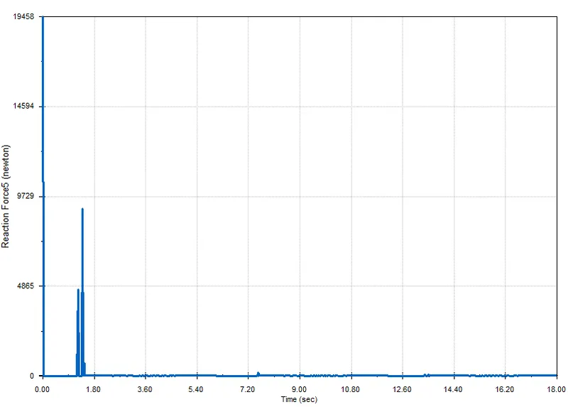
The contact force is the maximum magnitude in the starting then its became a linear .
2. Angular Displacement of the driven wheel:
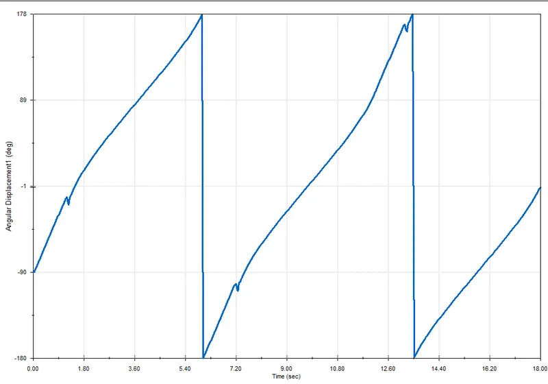
From plot-2 we can see that the angular velocity of the driven wheel is initially increased slightly after that we can see sudden drop and processed is being continue in same interval of time .
3. Contact forces with Precise contact:
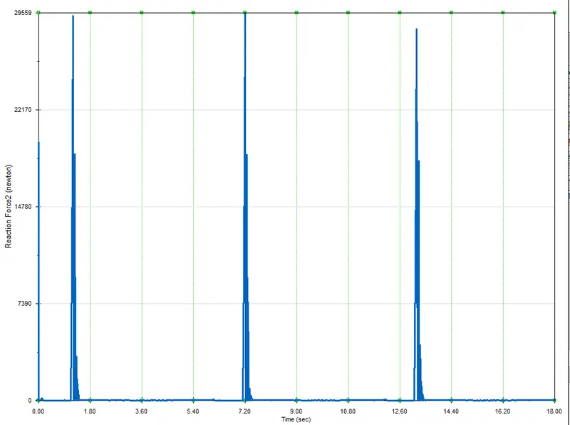
The contact force is continuously changing in a given time interval and we can calculate each and every point of a jerk as shown in the plot The Precise Contact gives a more accurate result.
3.4.2 Analysis at 20 RPM:
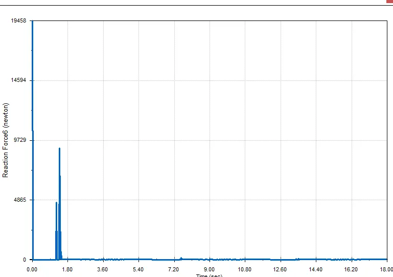
1. Contact force:
2. Angular Displacement of the driven wheel:
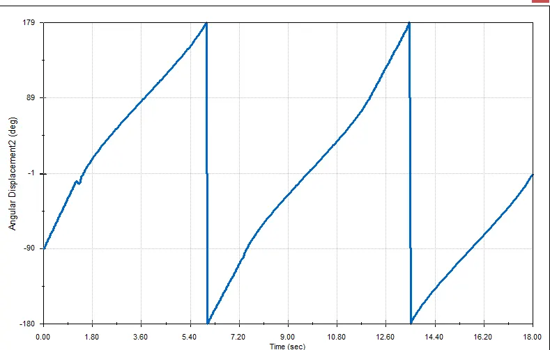
From plot-5 we can see that gradual increment and sudden decrement in the angular Displacement at 20 rpm. This trend is constant throughout the interval.
3. Contact forces with Precise contact at 120 FPS:
3.4.3 Angular velocity of Driver wheel at 20 RPM :
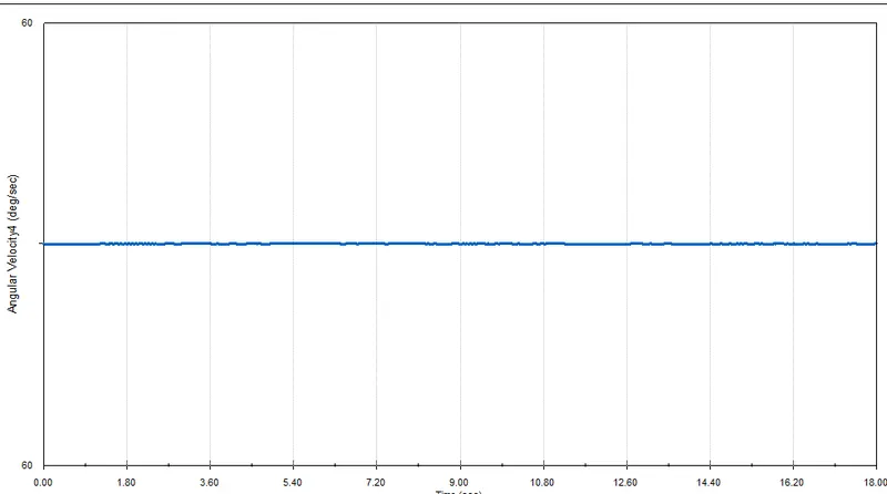
It seem angular velocity is constant throughout the displacement .
3.4.4 Comparing the contact forces with and without Precise contact:
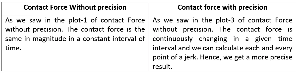
By comparing the contact forces with and without 'Precise Contact' we can conclude that the Precise Contact gives a more accurate result as we can see that the plots. we can also see the small variation in the plot with the help of Precise Contact.
4. Error & error elimination:-
The common error we can get during the motion analysis is the jerk.
The first cause of jerk is due to improper alignment of the driven wheel and drive wheel. This may cause serious damage to the real-life situation. Hence to avoid this error we need to align the drive and driven wheel by changing the centre distance between them.
The second cause of jerk is due to low rpm of the motor. Because gravity is acting on the driven wheel the small distortion in the position of the drive wheel occurs. hence, the key is unable to insert in the slot smoothly. To avoid that we can increase the rpm of the motor or set up our assembly arrangement in such a way that the gravity effect is zero.
Note:- Always Remember the unit system while doing part design and Assembly Design.
5.2 Conclusion:
When the driver tries to enter in the slot of the driven wheel it faces a jerk as the entry is not smooth. therefore, we can see from the plot, a sudden increase in the contact force at the entry to the slot. As we increase the rpm the angular displacement is also increased.