Induction motor characterstic
AIM: To study the induction motor and its different characteristics.
OBJECTIVES:
1. How induction motor operation is similar to the clutch?
2. Calculate the starting time of a drive with the following parameters:
J=10 kg-m2,
T = 15 + 0.5wm
Tl=5+0.6ωm
3. A drive has following equations for motor and load torques:
Tm=(1+2ωm)
Tl= 3 √ωm
Obtain the equilibrium points and determine the stability.
4. Make a MATLAB script file that will plot speed-torque characteristics for a frequency control method.
OBJECTIVE - 1. How induction motor operation is similar to the clutch?
The mechanical clutches and the induction motor have many things in common as the part of their working module and the working principle.
First, we will understand the working of both devices.
Mechanical Clutch
Clutch work on the principle of friction because when the two rough surface clutch plates come in contact with each other, they become rotating as a single unit. The clutch is located between the engine and the gearbox, mounted directly to the face of the engine flywheel.
The clutch connects and disconnects two rotating shafts, one shaft is typically attached to an engine while the output shaft provides output power for work.
The default state of the clutch is engaged, i.e. the connection between engine and gearbox is always on unless the driver presses the pedal and disengages it. If the engine is running with clutch engaged and the transmission is neutral, the engine spins the transmission's input shaft, but no power is transmitted to the wheels. Although the gearbox does not stop rotating during a gear change, there is no torque transmitted through it.
The output shaft of the gearbox is permanently connected to the final drive, then the wheel and so both always rotate together with the clutch disengaged, the gearbox input shaft is free to change its speed as the internal ratio is changed. Any resulting difference in speed between the engine and the gearbox is evened out as the clutch slips slightly during re-engagement.
Induction Motor-
The stator and rotor are two essential parts of the motor. The stator is the stationary part and it carries the overlapping winding while the rotor carries the main or field winding. The winding of the stator is equally displaced from each other by an angle of 120 degrees.
The induction motor is the single exited motor i.e stator. The term excitation means the process of inducing the magnetic field on the part of the motor. When the three-phase supply is given to the stator the rotating magnetic field produces on it. The torque induced on the conductor is known as electromagnetic torque.
The direction of electromagnetic torque and the rotating magnetic field is the same. Thus the rotor starts rotating in the same direction as that of the rotating magnetic field.
Comparing the Mechanical clutch to induction motor.
As mentioned above the driving shaft and driven shaft attached to the clutch are rotating at different speeds which causes a slip and clutch attempts to lock them together or release them. The slip that exists between the driver and the driven shaft is given by,
`ω_2 = ω_1(1-s)`
where
s - slip
`ω_1 =` Speed of driving shaft
`ω_ 2=` Speed of driving shaft
The operation of the clutch is similar to that of the induction motor in terms of the slip. In an induction motor, the speed of the rotor is always less than the rotating magnetic field or synchronous speed. The rotor tries to run at the speed of the rotor, but it always slips away. Thus the motor never runes at the speed of the rotating magnetic field, and this is the reason because of which the induction motor is also known as the synchronous speed no relative motion occurs between the rotating magnetic field of the stator and the conductor of the rotor. Thus the EMF is not induced on the conductor and zero current develops on it. Without current, the torque is also not produced. Because of the above mention reasons, the rotor is always less than the speed of the rotating magnetic field. This is why the slip occurs and it is given as,
`s = (N_s - N_r)/N_s`
Where,
s - slip
`N_s =` Synchronous speed
`N_r=` Speed of the Rotor
The above equation can be rearranged as follows,
`N_r = N_s(1-s)`
This states that the operation of the induction motor is similar to the clutch.
OBJECTIVE 2 -
Calculate the starting time of a drive with the following parameters:
J=10 kg-m2,
Tm = 15 + 0.5wm
Tl=5+0.6ωm
Solution-
Here
J - Moment of inertia
Tm - Motor torque
Tl - load torque
The steady-state stability equation for an induction motor is given by
`T_m - T_l = J ** (dω)/dt` ------------(1)
Where
`d ω` = ` Change in the angular velocity.
dt = Change in time
At steady state, the motor torque and the load torque is the same
`T_l = T_m`
`15 + 0.5 ω = 5 + 0.6 ω`
`0.1 ω = 10`
`ω = 100` rad/s
For calculating the starting time the values are substituted in equation 1
`(15 + 0.5 ω) -(5 + 0.6 ω) = 10 **(d ω)/dt`
`(d ω)/dt = (10 - 0.1 ω)/10`
`(d ω)/dt =1 - 0.01 ω`
`(d t)/(dω) =1/(1 - 0.01 ω)`
`d t =1/(1 - 0.01 ω)**dω`
Assuming 5% slip the speed will reduce to 95 rad/sec
hence
`ω1 = 0`rad/sec
`ω2 = 95`rad/sec
`:.intdt = int _0 ^95 1/(1-0.01ω) xx dω`
`:. t = (1/0.01) xx ln |1-0.01ω| + C`
Solving using the initial conditions t = 0, `ω = 0`
`:. C = 0`
`t = [(1 /0.01) xx ln |1 - 0.01ω|]`
`:. t = (2.99573 xx 100) - 0`
`:. t = 299.5 sec`
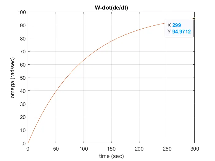
So the starting time for the motor is t = 299.5 sec.
CODE
Function code
function [W_dot]=omega(t,W)
W_dot=1-0.01*(W);
end
Main code
clc
clear all
close all

T_P = [0 299];
ic=[0 0];
[t,W]=ode45(@omega,T_P,ic);
plot(t,W);
title('W-dot(de/dt)')
xlabel('time (sec)')
ylabel('omega (rad/sec)')
grid on
Explanation-
- In this program, we have calculated the constant speed of the motor through the derivation.
- We are using the time of 0 to 299 sec because we derive the equation above and obtain this time value whereas the initial condition is referred to in the program.
- The function program is called here in main program for ode45 solver to differentiate at each time.
- The function in the name of omega (t,w) and the equation is W_dot = 1-0.01w.
- The equation is differentiated in that solver up to 299 sec.
- Therefore the constant speed of the drive is obtained in time (t) = 299 sec.
Output:
OBJECTIVE 3
A drive has following equations for motor and load torques:
Tm=(1+2ωm)
Tl= 3 √ωm
Solution
Condition for stability
`(dT_l)/(dω_m) - (dT_m)/(dω_m) > 0`
where
Tm = torque of motor
Tl = load torque
At steady state
`T_m =T_l`
`1+ 2ω_m =3sqrtω_m`
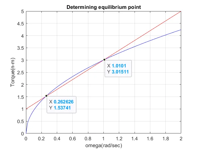
solving this we will get two equilibrium points
`ω_m = 0.25 and 1`
CODE
clc
clear all
close all

W=linspace(0,2);
%Tm and Tl equations are given in the question
Tm = 1+2*W;
Tl = 3*sqrt(W);
%plotting
plot(W,Tm,'r')
title('Determining equilibrium point')
xlabel('omega(rad/sec)')
ylabel('Torque(n-m)')
hold on
plot(W,Tl,'b');
legend('motor torqur','load torque');
grid on
Explanation-
- The two equilibrium point are obtained in this graph that is initiated as two dots and the value of wm = 0.25 and 1.
- Now we differentiate the load torque and motor torque in terms of motor speed therefore we get
`T_l = 3/2`
`T_m = 3`
- We substitute the value of motor speed wm = 0.25 and 1 in the equation and to obtain n stability point
- Substituting the value of motor speed wm = 0.25 in that equation
`T_l = 3/2`
`T_l = 3`
Hence Tl = 3 and Tm = 2 are obtained in motor speed of wm = 0.25 according to the condition of stability the value of load torque is greater than the value of the motor torque that system is considered as a stable condition.
- By substituting the value wm = 1 in that equation
`Tl = 3/2`
`T_l = 1.5`
- Hence the Tl = 1.5 and Tm = 2 are obtained in the motor speed of wm =1 according to the condition of stability the value of load torque is lesser than the value of the motor torque such system is considered an unstable condition.
Output
OBJECTIVE 4 - Make a MATLAB script file that will plot speed-torque characteristics for a frequency control method.
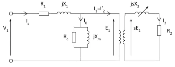
The Equivalent circuit for an induction motor is given below
here
R1 stator resistance
R2 Rotor resistance with respect to the stator
X1 Stator leakage reactance
Xm Magnetising reactance to cross air gap
Rc core losses
X2 Rotor reactance with respect to the stator
The torque developed by the induction motor is given by
`T = 3/(ω_m) ((V^2/s)/((R_1 + (R_2)/s)^2 + (X_1 +X_2)^2))`
Slip is given by
`s = (ω_ms - ω_m)/(ω_ms)`
`ω_ms = (4pif)/P`
clc
clear all
close all

%inputs

%voltage per phase
V=230/sqrt(3);
%number of phase
ph = 3;
%number of poles
p = 4;
%stator resistance and inductance
R1 = 0.095;
X1 = 0.680;
%rotor resistance and inductance
R2 = 0.095;
X2 = 0.680;
%magnetic inductance
Xm = 18.7;

%frequency range from 50Hz tok 150Hz
Fz = [50:20:150];
%for contineous variation
i = length (Fz)
for x = 1:i
    %motor speed calculation
    Ws = (4*pi*Fz(x))/p;
    Ns = (120*Fz(x))/p;
    for  n=1:200
         s=n/200;
         N(n) = Ns*(1-s)
         Zeq = (R1+R2*(1-s)/s)+(X1+X2);
         T(n) = 3*((V^2)*(R2/s))/(Ws*((R1+(R2/s)^2))+((X1+X2)^2))
    end
    %to display maximum speed of motor
    Curve = ['The maximum speed of motor at ',num2str(Fz(x)),'Hz is'];
   disp(Curve)
   disp(N(1))

   %plotting
   plot (N,T)
   hold on
   grid on
   title('Speed torque characterstic of induction motor')
   xlabel('speed of motor in (RPM)');
   ylabel('Torque of motor in (N-m)');
end
Explanation
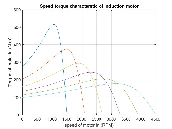
- Here the MATLAB script file all the parameters for speed and torque are provide
- After that 5 variable frequency is provided with a fixed interval.
- Then for calculating the angular speed and synchronous speed a function is defined which will vary the frequency by continuously increasing the value of 1 unit.
- Then slip is also carried in the range of 1 to 200.
- After that, all the inputs are given in the speed and torque equation by which we can further plot the characteristic curve of speed VS torque.
OUTPUT
CONCLUSION-
In the project, we have understood the similarities between the mechanical clutch and the induction motor. Successfully calculated the starting time of the conduction motor and found out the equilibrium points. Ploted the speed torque characteristic for frequency control.